2010 JAGUAR XFR fuse
[x] Cancel search: fusePage 2414 of 3039
Published: 24-Jan-2013
Glass, Frames and Mechanisms - Glass, Frames and Mechanisms - System
Operation and Component Description
Description and Operation
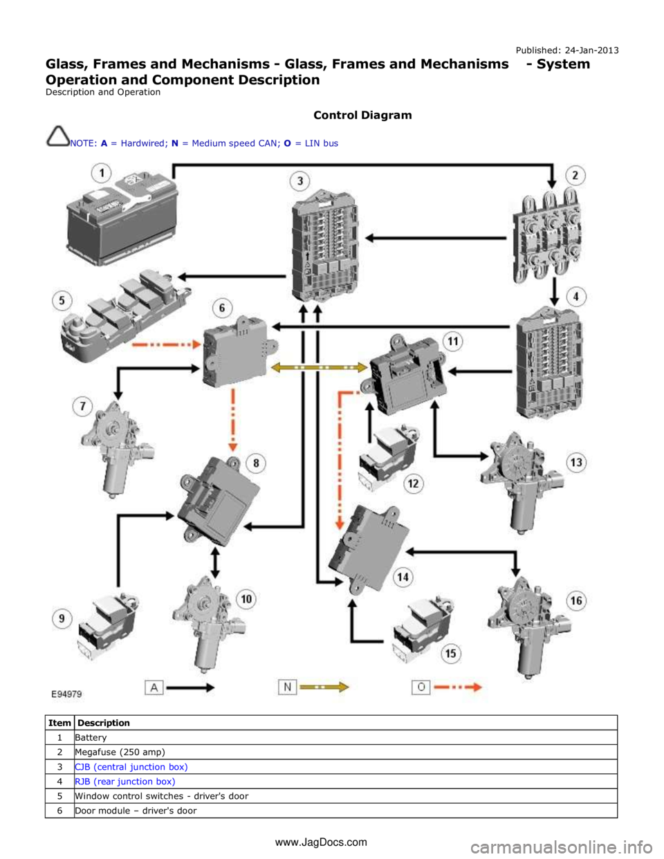
Control Diagram
NOTE: A = Hardwired; N = Medium speed CAN; O = LIN bus
Item Description 1 Battery 2 Megafuse (250 amp) 3 CJB (central junction box) 4 RJB (rear junction box) 5 Window control switches - driver's door 6 Door module – driver's door www.JagDocs.com
Page 2417 of 3039
Published: 07-Mar-2014
Glass, Frames and Mechanisms - Glass, Frames and Mechanisms
Diagnosis and Testing
Principle of Operation
For a detailed description of the glass, frames and mechanisms, refer to the relevant Description and Operation section in the
workshop manual. REFER to: (501-11 Glass, Frames and Mechanisms)
Glass, Frames and Mechanisms (Description and Operation), Glass, Frames and Mechanisms (Description and Operation), Glass, Frames and Mechanisms (Description and Operation).
Inspection and Verification
CAUTION: Diagnosis by substitution from a donor vehicle is NOT acceptable. Substitution of control modules does not
guarantee confirmation of a fault, and may also cause additional faults in the vehicle being tested and/or the donor vehicle.
1. Verify the customer concern by operating the system
2. Visually inspect for obvious signs of damage and system integrity
Visual Inspection
Mechanical Electrical
Window glass
Door window regulator
Window seals
Fuse(s)
Door window regulator motor
Loose or corroded electrical connector(s)
Switch
Circuit(s)
3. If an obvious cause for an observed or reported concern is found, correct the cause (if possible) before proceeding to
the next step
4. If the concern is not visually evident, check for Diagnostic Trouble Codes (DTCs) and refer to the DTC index
Window Regulator Diagnostic
This diagnostic procedure is to be carried out if the door window either: closes to the top, then reopens (Bounce back); does
not fully close to the top of the door frame; the one touch function is disabled
PINPOINT TEST A : DIAGNOSTIC PROCEDURE TEST
CONDITIONS DETAILS/RESULTS/ACTIONS A1: DOOR WINDOW - SEAL CONDITION / FOREIGN MATERIAL
NOTE: To check that the door window seal is free from foreign material and has no sign of damage and is not worn in the
door channels 1 Carry out visual inspection for: Foreign material
Obstruction
Signs of damage or wear to door window seal Is the door window seal free from foreign material, damage and wear?
Yes
GO to A2. No
Remove any foreign material or were necessary install new door window seal. Test the system for
correct operation A2: DOOR WINDOW - SEAL INSTALLATION
NOTE: To check that the door window seal is installed correctly 1 Check that the door window seal is installed correctly, ensure that it is fully installed into the corner areas Is the door window seal installed correctly?
Yes
GO to A3. No
Page 2490 of 3039
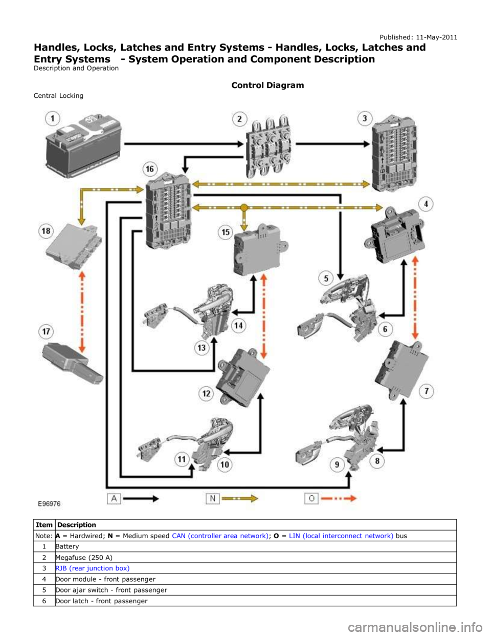
Note: A = Hardwired; N = Medium speed CAN (controller area network); O = LIN (local interconnect network) bus 1 Battery 2 Megafuse (250 A) 3 RJB (rear junction box) 4 Door module - front passenger 5 Door ajar switch - front passenger 6 Door latch - front passenger
Page 2492 of 3039
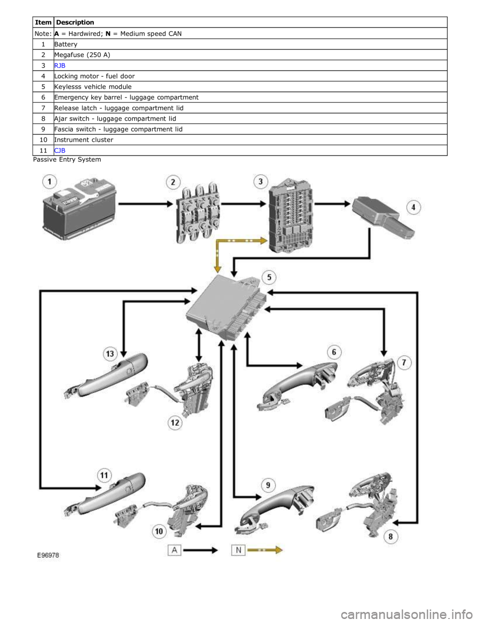
Note: A = Hardwired; N = Medium speed CAN 1 Battery 2 Megafuse (250 A) 3 RJB 4 Locking motor - fuel door 5 Keylesss vehicle module 6 Emergency key barrel - luggage compartment 7 Release latch - luggage compartment lid 8 Ajar switch - luggage compartment lid 9 Fascia switch - luggage compartment lid 10 Instrument cluster 11 CJB Passive Entry System
Page 2493 of 3039

Item Description Note: A = Hardwired; N = Medium speed CAN 1 Battery 2 Megafuse (250 A) 3 CJB 4 Radio frequency receiver 5 Keylesss vehicle module 6 Door handle, lock/unlock switch and antenna - front passenger 7 Door latch, fast latch - front passenger 8 Door latch, fast latch - RH rear passenger 9 Door handle, lock/unlock switch and antenna - RH rear passenger 10 Door latch, fast latch - LH rear passenger 11 Door handle, lock/unlock switch and antenna - LH rear passenger 12 Door latch, fast latch - driver door 13 Door handle, lock/unlock switch and antenna - driver door
System Operation
The hinged panels are secured with latches and strikers. A remotely operated central locking system controls the locking and
unlocking of the door and luggage compartment latches. A radio frequency Smart Key allows the vehicle to be locked and
unlocked by pressing the appropriate handset buttons. Two levels of central locking system are available: remote central
locking and an optional passive entry system.
The passive entry and associated passive start system allows the driver to unlock and start the vehicle without using a vehicle
key in a door-lock or ignition switch. The passive entry system is an optional fitment while the passive start system is a
standard fitment on all vehicles. The passive start system is combined with the passive anti-theft immobilization system.
Refer to: Anti-Theft - Passive (419-01B Anti-Theft - Passive, Description and Operation).
Emergency access to the vehicle is provided by two concealed key barrels: one located in the front left-hand door handle and
one located on the underside of the luggage compartment lid finisher. An emergency, removable key blade is fitted into the
Smart Key.
Operation of either key barrel unlocks the vehicle but does not disarm the alarm system. The key barrels in the door and
luggage compartment lid are concealed by a plastic cover which can be removed by inserting the blade of the emergency key
into a slot in the cover.
Locking and unlocking conditions using the emergency key in the door key barrel:
If the alarm is not armed the vehicle can be centrally unlocked.
If the alarm is armed the door only can be opened and the alarm will be triggered.
The vehicle cannot be double locked or the alarm system armed using the emergency key.
The vehicle can be centrally locked and unlocked from inside using the interior handle release levers on the front doors only.
Central locking and unlocking can also be performed using lock and unlock buttons on the vehicle's fascia. The driver can select
locking options, single point entry or drive away locking for example, from a menu available on the touch screen.
Central Locking – Radio Frequency Remote System
The radio frequency central locking system, provides locking and unlocking of the vehicle from inside and outside of the
vehicle. The system is operated using buttons on the Smart Key, which transmits radio frequency signals to the central locking
radio frequency receiver.
The system provides additional security by double-locking the doors from outside the vehicle if the lock button, on the Smart
Key, is pressed twice within 3 seconds; this function is not applicable in North American Specification (NAS) and Japanese
markets.
Additional buttons on the Smart Key provide for the convenience operation of the luggage compartment lid release, headlamp
delay and panic alarm functions. A global open or close feature is also available in certain markets using the lock/unlock
buttons.
Passive Entry
On vehicles fitted with the optional passive entry system, the vehicle can be unlocked without the use of a key blade or
pressing buttons on the Smart Key. The Smart Key operates the passive entry system in addition to the passive start system.
Refer to: Anti-Theft - Passive (419-01B Anti-Theft - Passive, Description and Operation).
The passive entry system is controlled by the keyless vehicle module and five low frequency antennas. One antenna located in
each door handle and one antenna located behind the rear bumper cover.
When a vehicle door handle is pulled to the first five-percent of its travel and the Smart Key is within one meter of the handle;
the Smart Key receives the low-frequency signal transmitted from the keyless vehicle module. The Smart Key responds with a
radio frequency transmission of its authorization code. The radio frequency signal is received by the central locking radio-
frequency receiver and passed to the keyless vehicle module which checks and approves the code as valid. Once the handle is
Page 2495 of 3039
Published: 18-Mar-2014
Handles, Locks, Latches and Entry Systems - Locks, Latches and Entry Systems
Diagnosis and Testing
Principle of Operation
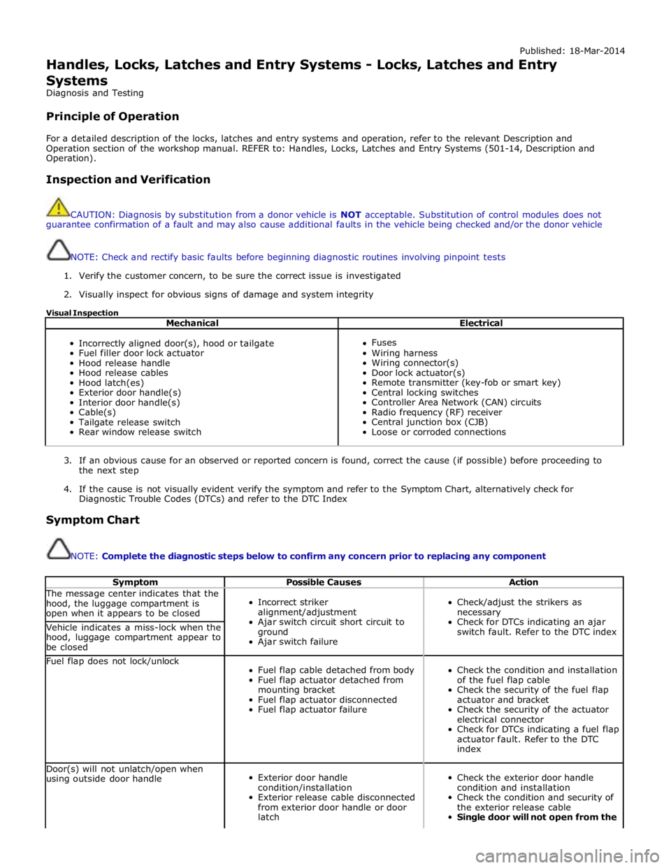
For a detailed description of the locks, latches and entry systems and operation, refer to the relevant Description and
Operation section of the workshop manual. REFER to: Handles, Locks, Latches and Entry Systems (501-14, Description and
Operation).
Inspection and Verification
CAUTION: Diagnosis by substitution from a donor vehicle is NOT acceptable. Substitution of control modules does not
guarantee confirmation of a fault and may also cause additional faults in the vehicle being checked and/or the donor vehicle
NOTE: Check and rectify basic faults before beginning diagnostic routines involving pinpoint tests
1. Verify the customer concern, to be sure the correct issue is investigated
2. Visually inspect for obvious signs of damage and system integrity
Visual Inspection
Mechanical Electrical
Incorrectly aligned door(s), hood or tailgate
Fuel filler door lock actuator
Hood release handle
Hood release cables
Hood latch(es)
Exterior door handle(s)
Interior door handle(s)
Cable(s)
Tailgate release switch
Rear window release switch
Fuses
Wiring harness
Wiring connector(s)
Door lock actuator(s)
Remote transmitter (key-fob or smart key)
Central locking switches
Controller Area Network (CAN) circuits
Radio frequency (RF) receiver
Central junction box (CJB)
Loose or corroded connections
3. If an obvious cause for an observed or reported concern is found, correct the cause (if possible) before proceeding to
the next step
4. If the cause is not visually evident verify the symptom and refer to the Symptom Chart, alternatively check for
Diagnostic Trouble Codes (DTCs) and refer to the DTC Index
Symptom Chart
NOTE: Complete the diagnostic steps below to confirm any concern prior to replacing any component
Symptom Possible Causes Action The message center indicates that the
hood, the luggage compartment is
open when it appears to be closed
Incorrect striker
alignment/adjustment
Ajar switch circuit short circuit to
ground
Ajar switch failure
Check/adjust the strikers as
necessary
Check for DTCs indicating an ajar
switch fault. Refer to the DTC index Vehicle indicates a miss-lock when the
hood, luggage compartment appear to
be closed Fuel flap does not lock/unlock
Fuel flap cable detached from body
Fuel flap actuator detached from
mounting bracket
Fuel flap actuator disconnected
Fuel flap actuator failure
Check the condition and installation
of the fuel flap cable
Check the security of the fuel flap
actuator and bracket
Check the security of the actuator
electrical connector
Check for DTCs indicating a fuel flap
actuator fault. Refer to the DTC
index Door(s) will not unlatch/open when
using outside door handle
Exterior door handle
condition/installation
Exterior release cable disconnected
from exterior door handle or door
latch
Check the exterior door handle
condition and installation
Check the condition and security of
the exterior release cable
Single door will not open from the
Page 2543 of 3039
Wipers and Washers - Wipers and Washers
Diagnosis and Testing
Principle of Operation Published: 11-May-2011
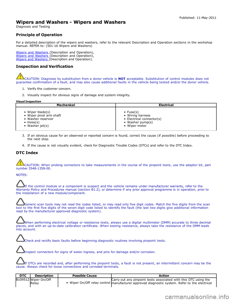
For a detailed description of the wipers and washers, refer to the relevant Description and Operation sections in the workshop
manual. REFER to: (501-16 Wipers and Washers)
Wipers and Washers (Description and Operation), Wipers and Washers (Description and Operation), Wipers and Washers (Description and Operation).
Inspection and Verification
CAUTION: Diagnosis by substitution from a donor vehicle is NOT acceptable. Substitution of control modules does not
guarantee confirmation of a fault, and may also cause additional faults in the vehicle being tested and/or the donor vehicle.
1. Verify the customer concern.
2. Visually inspect for obvious signs of damage and system integrity.
Visual Inspection
Mechanical Electrical
Wiper blade(s)
Wiper pivot arm shaft
Washer reservoir
Hose(s)
Washer jet(s)
Fuse(s)
Wiring harness
Electrical connector(s)
Washer pump(s)
Wiper motor
3. If an obvious cause for an observed or reported concern is found, correct the cause (if possible) before proceeding to
the next step.
4. If the cause is not visually evident, check for Diagnostic Trouble Codes (DTCs) and refer to the DTC Index.
DTC Index
CAUTION: When probing connectors to take measurements in the course of the pinpoint tests, use the adaptor kit, part
number 3548-1358-00.
NOTES:
If the control module or a component is suspect and the vehicle remains under manufacturer warranty, refer to the
Warranty Policy and Procedures manual (section B1.2), or determine if any prior approval programme is in operation, prior to
the installation of a new module/component.
Generic scan tools may not read the codes listed, or may read only five digit codes. Match the five digits from the scan
tool to the first five digits of the seven digit code listed to identify the fault (the last two digits give additional information
read by the manufacturer approved diagnostic system).
When performing electrical voltage or resistance tests, always use a digital multimeter (DMM) accurate to three decimal
places, and with an up-to-date calibration certificate. When testing resistance, always take the resistance of the DMM leads
into account.
Check and rectify basic faults before beginning diagnostic routines involving pinpoint tests.
Inspect connectors for signs of water ingress, and pins for damage and/or corrosion.
If DTCs are recorded and, after performing the pinpoint tests, a fault is not present, an intermittent concern may be the
cause. Always check for loose connections and corroded terminals.
DTC Description Possible Cause Action B109512
Wiper On/Off
Relay
Wiper On/Off relay control Carry out any pinpoint tests associated with this DTC using the
manufacturer approved diagnostic system. Refer to the electrical
Page 2561 of 3039
Published: 11-May-2011
Roof Opening Panel - Roof Opening Panel - System Operation and
Component Description
Description and Operation
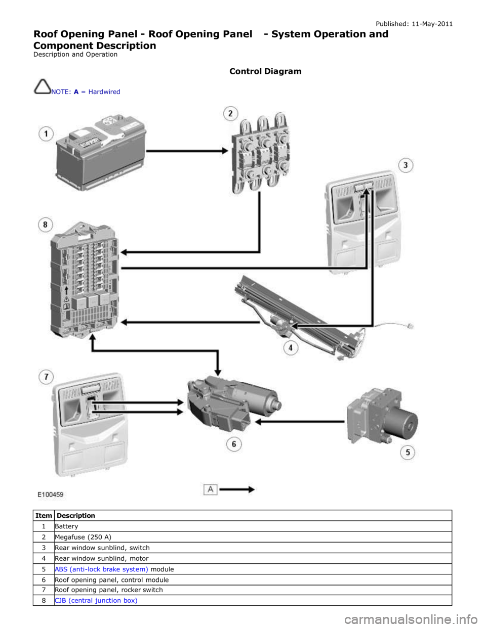
Control Diagram
NOTE: A = Hardwired
Item Description 1 Battery 2 Megafuse (250 A) 3 Rear window sunblind, switch 4 Rear window sunblind, motor 5 ABS (anti-lock brake system) module 6 Roof opening panel, control module 7 Roof opening panel, rocker switch 8 CJB (central junction box)