2010 JAGUAR XFR fuse
[x] Cancel search: fusePage 2017 of 3039
Is the USB extension cable securely pushed into the USB connection port on the audio input control module
Yes
Replace the USB extension cable
No
Secure connections and retest B4: CHECK THE CAPACITY OF THE MEMORY STICK/STORAGE DEVICE
NOTE: The higher the capacity of the memory stick is the longer it takes to register with the audio input control module
and power up. The maximum permitted capacity is 8 Gigabytes 1 Check the storage capacity of the memory stick/storage device does not exceed 8 Gigabytes Is the storage capacity of the memory stick/storage device 8 Gigabytes or less?
Yes
High capacity devices may require longer to register and should be allowed up to two minutes to power up
following connection to the USB port. If memory stick fails to power up after two minutes, suspect a
faulty memory stick GO to B2. or USB extension cable GO to B3. No
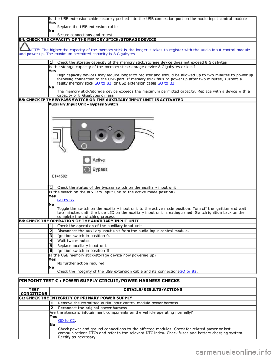
The memory stick/storage device exceeds the maximum permitted capacity. Replace with a device with a capacity of 8 Gigabytes or less B5: CHECK IF THE BYPASS SWITCH ON THE AUXILIARY INPUT UNIT IS ACTIVATED Auxiliary Input Unit - Bypass Switch
1 Check the status of the bypass switch on the auxiliary input unit Is the switch on the auxiliary input unit to the active mode position?
Yes
GO to B6. No
Toggle the switch on the auxiliary input unit to the active mode position. Turn off the ignition and wait
two minutes until the blue LED on the auxiliary input unit is extinguished. Switch ignition back on the complete the switching process B6: CHECK THE OPERATION OF THE AUXILIARY INPUT UNIT 1 Check the operation of the auxiliary input unit 2 Disconnect the auxiliary input unit from the audio input control module. 3 Ignition switch in position 0. 4 Wait two minutes 5 Replace auxiliary input unit 6 Ignition switch in position II. Is the USB memory stick/storage device now powering up?
Yes
No further action required
No
Check the integrity of the USB extension cable and its connectionsGO to B3.
PINPOINT TEST C : POWER SUPPLY CIRCUIT/POWER HARNESS CHECKS TEST
CONDITIONS DETAILS/RESULTS/ACTIONS C1: CHECK THE INTEGRITY OF PRIMARY POWER SUPPLY 1 Remove the retrofitted audio input control module power harness 2 Reconnect the original power harness Are the standard infotainment components on the vehicle operating normally?
Yes
GO to C2. No
Check power and ground connections to the affected modules. Check for related power or lost
communications DTCs and refer to the relevant DTC index. Check fuses and battery charging system. Rectify as necessary
Page 2025 of 3039
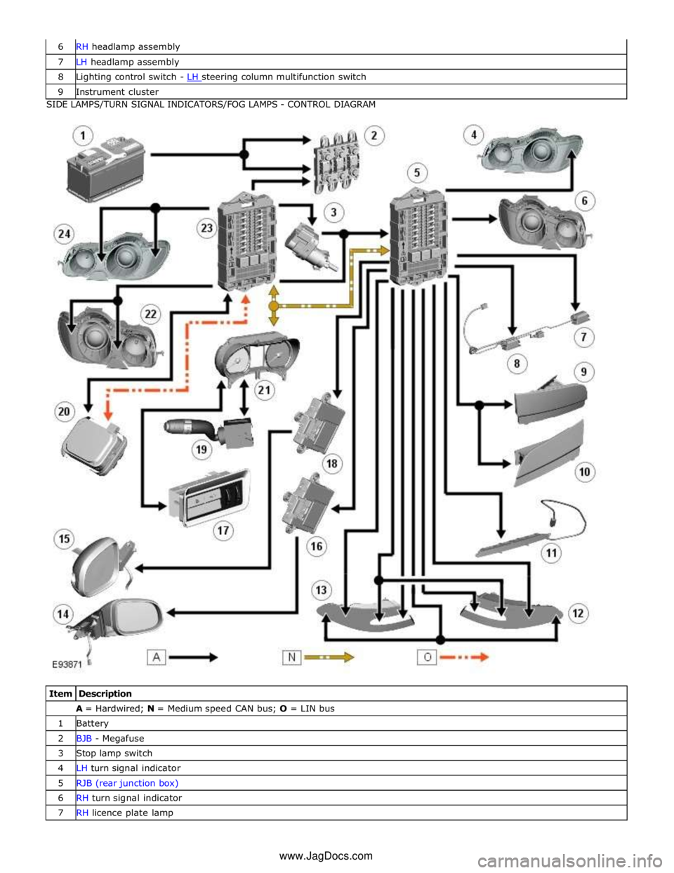
7 LH headlamp assembly 8 Lighting control switch - LH steering column multifunction switch 9 Instrument cluster SIDE LAMPS/TURN SIGNAL INDICATORS/FOG LAMPS - CONTROL DIAGRAM
Item Description A = Hardwired; N = Medium speed CAN bus; O = LIN bus 1 Battery 2 BJB - Megafuse 3 Stop lamp switch 4 LH turn signal indicator 5 RJB (rear junction box) 6 RH turn signal indicator 7 RH licence plate lamp www.JagDocs.com
Page 2027 of 3039
by Field Effect Transistors (FET's). The FET's can detect overloads and short circuits and respond to heat generated by
increased current flow caused by a short circuit.
On a normal conventionally protected circuit this would cause a fuse to blow. The FET's respond to the heat increase and
disconnect the power supply to the affected circuit. When the fault is rectified or the FET has cooled, the FET will reset and
operate the circuit normally. If the fault persists the FET will cycle, disconnecting and reconnecting the power supply.
The CJB and the RJB store fault codes which can be retrieved using a Jaguar approved diagnostic system. The fault code will identify that there is a fault on a particular output circuit which will assist with fault diagnosis and detection.
Alarm Indications
The exterior lighting system is used for alarm arm and disarm requests to show alarm system status.
When the driver locks and arms the vehicle, a visual indication of a successful lock and arm request is displayed to the driver
by a single flash of the hazard flashers. If the vehicle is superlocked, then the hazard flashers will flash a second time (200 ms
off and 200 ms on) to confirm the superlock request.
If the alarm is activated, the hazard flashers are operated for 10, 30 second cycles of 200 ms on and 200 ms off, with a 10
second delay between each cycle.
NOTE: On North American Specification (NAS) vehicles, the delay between the cycle when the alarm is activated is 60
seconds.
Lights on Warning
When the ignition is in the off power mode 0 or accessory power mode 4 and the lighting control switch is in the side lamp or
headlamp position, a warning chime will sound if the driver's door is opened. This indicates to the driver that the exterior
lights have been left switched on.
The chime is generated from the instrument cluster sounder on receipt of a lights on signal, a driver's door open signal and an
ignition off power mode 0 or accessory power mode 4 signal via a medium speed CAN bus signal from the CJB. Headlamp Timer
The RJB controls the headlamp timer function which allows the headlamps to remain on for a period of time after leaving the vehicle. This is a driver convenience feature which illuminates the driveway after leaving the vehicle.
To operate the timer function the lighting control switch must be in one of the three headlamp timer positions when the
ignition status is changed from ignition on power mode 6 to the off power mode 0. The timer function will then be initiated and
the low beam headlamps will be illuminated for the selected timer period.
NOTE: If the lighting switch is in the AUTO position, the headlamp timer will not function when the ignition is changed to
off power mode 0.
When the lighting control switch is in the autolamp exit delay position, the lighting control switch reference voltage flows
through 4 of the resistors. The returned signal voltage is detected by the instrument cluster which outputs a message on the
medium speed CAN bus to the RJB that autolamps has been selected.
Depending on the selected exit delay position, the reference voltage to the autolamp exit delay switch is routed through 3, 2
or 1 resistors which is detected by the instrument cluster. The cluster outputs a message on the medium speed CAN bus to the RJB that autolamp exit delay period has been selected at 30, 60 or 120 seconds respectively. Crash Signal Activation
When a crash signal is transmitted from the RCM (restraints control module), the RJB activates the hazard flashers. The hazard flashers continue to operate until the ignition is in the off power mode 0 or accessory power mode 6. Once this ignition state
has occurred, the RCM will cease to transmit the crash signal.
LIGHTING CONTROL SWITCH
The instrument cluster outputs 2 reference voltages to the rotary lighting control switch; one feed being supplied to the light
selection function of the switch and the second feed being supplied to the auto headlamp exit delay function. The switch
position is determined by instrument cluster by the change in returned signal voltage which is routed through up to 4 resistors
in series depending on the selection made.
OFF - When the lighting control switch is in the off position, the reference voltage flows through 1 of the resistors. The
returned signal voltage is detected by the instrument cluster which outputs a message on the medium speed CAN bus to the CJB that no lighting selection is made. The reference voltage to the auto headlamp exit delay switch is routed through 4 resistors which is detected by the instrument cluster which outputs a message on the medium speed CAN bus to the CJB that auto headlamp or exit delay has not been selected.
SIDE LAMPS - When the lighting control switch is in the side lamp position, the reference voltage flows through 2 of the
resistors. The returned signal voltage is detected by the instrument cluster which outputs a message on the medium speed
CAN bus to the CJB to activate the side lamps. The reference voltage to the autolamp exit delay switch is routed through 4 resistors which is detected by the instrument cluster which outputs a message on the medium speed CAN bus to the CJB that auto headlamp or exit delay has not been selected.
HEADLAMPS - When the lighting control switch is in the headlamp position, the reference voltage flows through 3 of the
Page 2037 of 3039
Exterior Lighting - Headlamps
Diagnosis and Testing
Principles of Operation Published: 11-Jul-2014
For a detailed description of the exterior lighting system, refer to the relevant Description and Operation section in the
workshop manual. REFER to: (417-01 Exterior Lighting)
Exterior Lighting (Description and Operation), Exterior Lighting (Description and Operation), Exterior Lighting (Description and Operation).
Safety Information
WARNINGS:
The Xenon Headlamp system generates up to 28,000 volts. Make sure that the headlamps are switched off before
working on the system. Failure to follow this instruction may lead to fatality.
The following safety precautions must be followed when working on the Xenon Headlamp system:
DO NOT attempt any procedures on the Xenon Headlamps or circuits when the system is energized.
Handling of the xenon bulb must be performed using suitable protective equipment, e.g. gloves and goggles. The glass
part of the bulb must not be touched.
Only operate the lamp in a mounted condition in the reflector.
All safety procedures and precautions must be followed to prevent personal injury.
CAUTION: Xenon bulbs must be disposed of as hazardous waste.
There are instructions on the correct procedures for Xenon Headlamp System repairs in the manual, refer to section 100-00 -
General Information, Standard Workshop Practices of the workshop manual.
Inspection and Verification
CAUTION: Diagnosis by substitution from a donor vehicle is NOT acceptable. Substitution of control modules does not
guarantee confirmation of a fault, and may also cause additional faults in the vehicle being tested and/or the donor vehicle.
1. Verify the customer concern.
2. Visually inspect for obvious signs of damage.
3. If an obvious cause for an observed or reported concern is found, correct the cause (if possible) before proceeding to
the next step.
4. If the cause is not visually evident, check for Diagnostic Trouble Codes (DTCs) and refer to DTC Index.
Symptom Chart
Symptom Possible Causes Action Low beam lamp(s)
inoperative
Bulb failure
Fuse(s) blown
Circuit fault
Lighting control switch
fault
Left-hand steering
column multifunction
switch fault Check the bulb and fuse condition (see visual inspection). Check the
headlamp circuits. Check the lighting control switch function. Check the
left-hand steering column multifunction switch operation. Refer to the
electrical guides. Check for DTCs indicating a headlamp or related circuit
fault. High beam lamp(s)
inoperative Electrical
Headlamp Leveling Module (HLM)
Bulb(s)
Photocell(s)
Ballast
Wiring harness/electrical connectors
Fuse(s) Visual Inspection
Page 2038 of 3039

Symptom Possible Causes Action Low beam lamp(s)
dim
Incorrect bulb rating
Tourist lever set in the
wrong position
Circuit fault
Lighting control switch
fault
Left-hand steering
column multifunction
switch fault Check the bulb condition and rating. Check the tourist lever is set
correctly. Check the headlamp circuits. Check the lighting control switch
function. Check the left-hand steering column multifunction switch
function. Refer to the electrical guides. High beam lamp(s)
dim Low beam lamp(s)
stuck on
Circuit fault
Lighting control switch
fault
Left-hand steering
column multifunction
switch fault
Headlamp timer
function fault Check the headlamp circuits. Check the lighting control switch function.
Check the left-hand steering column multifunction switch operation. Check
the headlamp timer function. Refer to the electrical guides. Check for DTCs
indicating a headlamp circuit fault High beam lamp(s)
stuck on Headlamp low/high
beam switching
function inoperative
Circuit fault
Left-hand steering
column multifunction
switch fault
Xenon lamp shutter
mechanism fault Check the headlamp circuits. Check the left-hand steering column
multifunction switch operation. Check the xenon lamp shutter mechanism
operation. Refer to the electrical guides. Check for DTCs indicating a
headlamp circuit fault Warning lamp(s)
inoperative
Fuse(s) blown
Lighting control switch
fault
Left-hand steering
column multifunction
switch inoperative
Circuit fault
Instrument cluster
fault Check the fuse(s) (see visual inspection). Check the lighting control switch
function. Check the left-hand steering column multifunction switch
function. Check the warning lamp circuits. Refer to the electrical guides.
Check for DTCs indicating an instrument cluster or CAN system fault. Headlamp Wet -
Internal
Condensation
Water Ingress Check for outstanding Technical Service Bulletins (TSBs) relating to
'Headlamp Internal Condensation'. Carry out the instructions in the service
bulletin to determine if the fault is related to condensation or water ingress. DTC Index
For a list of Diagnostic Trouble Codes (DTCs) that could be logged on this vehicle, please refer to Section 100-00. REFER to:
Diagnostic Trouble Code (DTC) Index - DTC: Headlamp Control Module (HCM) (100-00 General Information, Description and Operation).
Page 2056 of 3039
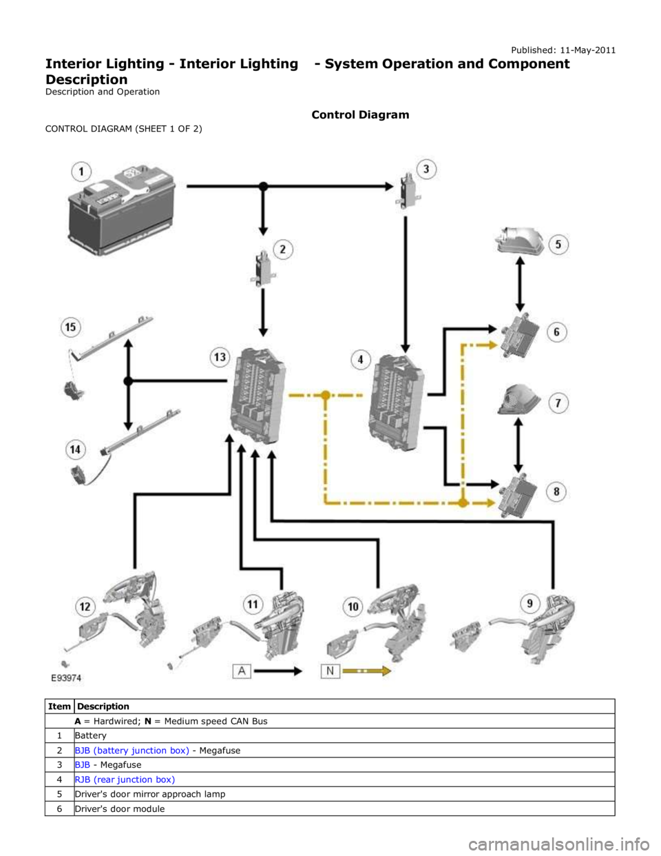
A = Hardwired; N = Medium speed CAN Bus 1 Battery 2 BJB (battery junction box) - Megafuse 3 BJB - Megafuse 4 RJB (rear junction box) 5 Driver's door mirror approach lamp 6 Driver's door module
Page 2057 of 3039
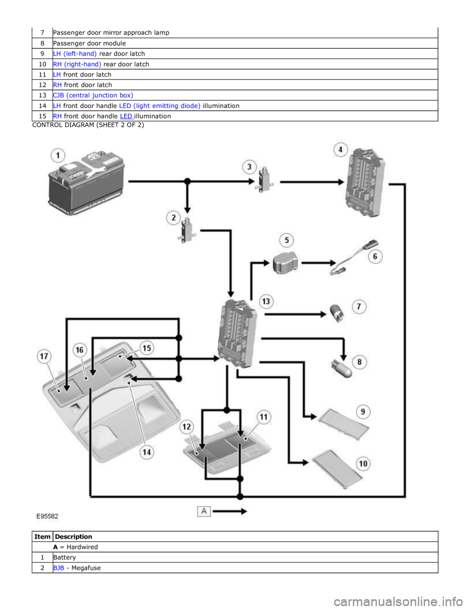
8 Passenger door module 9 LH (left-hand) rear door latch 10 RH (right-hand) rear door latch 11 LH front door latch 12 RH front door latch 13 CJB (central junction box) 14 LH front door handle LED (light emitting diode) illumination 15 RH front door handle LED illumination CONTROL DIAGRAM (SHEET 2 OF 2)
Item Description A = Hardwired 1 Battery 2 BJB - Megafuse
Page 2058 of 3039
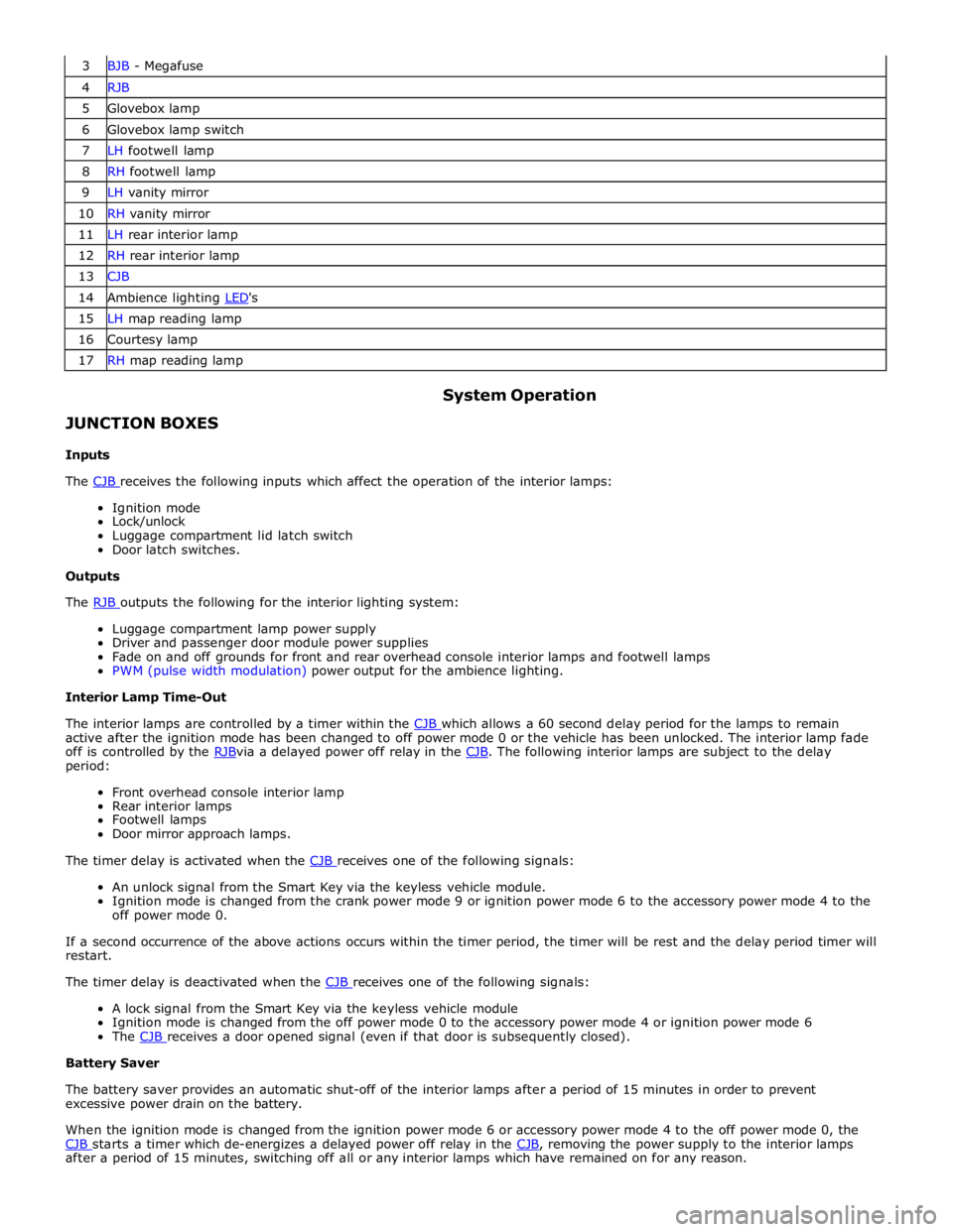
3 BJB - Megafuse 4 RJB 5 Glovebox lamp 6 Glovebox lamp switch 7 LH footwell lamp 8 RH footwell lamp 9 LH vanity mirror 10 RH vanity mirror 11 LH rear interior lamp 12 RH rear interior lamp 13 CJB 14 Ambience lighting LED's 15 LH map reading lamp 16 Courtesy lamp 17 RH map reading lamp
JUNCTION BOXES
Inputs System Operation
The CJB receives the following inputs which affect the operation of the interior lamps: Ignition mode
Lock/unlock
Luggage compartment lid latch switch
Door latch switches.
Outputs
The RJB outputs the following for the interior lighting system: Luggage compartment lamp power supply
Driver and passenger door module power supplies
Fade on and off grounds for front and rear overhead console interior lamps and footwell lamps
PWM (pulse width modulation) power output for the ambience lighting.
Interior Lamp Time-Out
The interior lamps are controlled by a timer within the CJB which allows a 60 second delay period for the lamps to remain active after the ignition mode has been changed to off power mode 0 or the vehicle has been unlocked. The interior lamp fade
off is controlled by the RJBvia a delayed power off relay in the CJB. The following interior lamps are subject to the delay period:
Front overhead console interior lamp
Rear interior lamps
Footwell lamps
Door mirror approach lamps.
The timer delay is activated when the CJB receives one of the following signals: An unlock signal from the Smart Key via the keyless vehicle module.
Ignition mode is changed from the crank power mode 9 or ignition power mode 6 to the accessory power mode 4 to the
off power mode 0.
If a second occurrence of the above actions occurs within the timer period, the timer will be rest and the delay period timer will
restart.
The timer delay is deactivated when the CJB receives one of the following signals: A lock signal from the Smart Key via the keyless vehicle module
Ignition mode is changed from the off power mode 0 to the accessory power mode 4 or ignition power mode 6
The CJB receives a door opened signal (even if that door is subsequently closed). Battery Saver
The battery saver provides an automatic shut-off of the interior lamps after a period of 15 minutes in order to prevent
excessive power drain on the battery.
When the ignition mode is changed from the ignition power mode 6 or accessory power mode 4 to the off power mode 0, the
CJB starts a timer which de-energizes a delayed power off relay in the CJB, removing the power supply to the interior lamps after a period of 15 minutes, switching off all or any interior lamps which have remained on for any reason.