2010 JAGUAR XFR window
[x] Cancel search: windowPage 2561 of 3039
Published: 11-May-2011
Roof Opening Panel - Roof Opening Panel - System Operation and
Component Description
Description and Operation
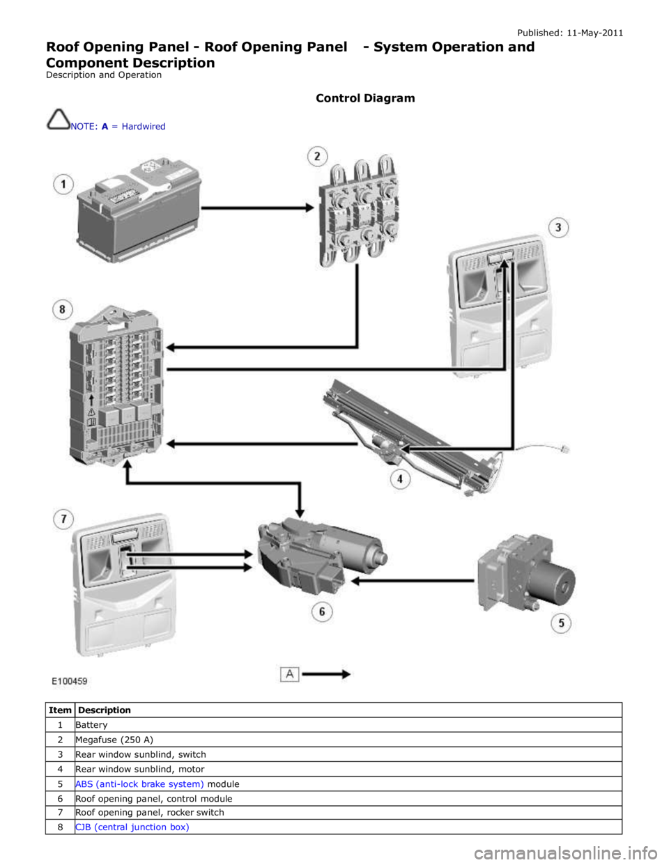
Control Diagram
NOTE: A = Hardwired
Item Description 1 Battery 2 Megafuse (250 A) 3 Rear window sunblind, switch 4 Rear window sunblind, motor 5 ABS (anti-lock brake system) module 6 Roof opening panel, control module 7 Roof opening panel, rocker switch 8 CJB (central junction box)
Page 2562 of 3039

Roof opening panel System Operation
Operation of the roof opening panel is controlled by the roof opening panel control module, which is integral with the motor.
The control module receives inputs from the CJB, which provides an 'open' or 'close' signal for remote handset operation, and
an 'enable' signal when the vehicle enters power mode 6.
The control module also receives a vehicle speed signal from the ABS module. The vehicle speed signal is used by the control
module to calibrate the anti-trap feature.
If the battery is disconnected, or the power supply is interrupted while the roof opening panel is in a partially open position,
the motor and control module will need to be calibrated to restore full functionality. To recalibrate:
1. Switch ignition on.
2. Press the front of the switch, so the roof opening panel is the tilt position, and then release the switch.
3. Press the front of the switch and hold for thirty seconds.
4. After thirty seconds the roof opening panel will begin to move. Keep the front of the switch pressed until the roof
opening panel has fully opened and then closed.
5. Once the open/close cycle has completed and the roof opening panel has stopped moving, release the switch.
6. The roof opening panel can now be operated as normal.
Drain hoses are connected to the front and rear corners of the roof opening panel frame. The drain hoses are located inside of
the cabin on the 'A' and 'D' post pillars to allow water, which has collected in the frame, to escape. One-way valves fitted to
the end of each drain hose, prevent the ingress of dirt and moisture.
Rear window sunblind
The powered rear window sunblind is operated through a switch in the roof console. Power to the sunblind motor is provided by
a pair of relays located in the CJB when the vehicle enters power mode 4. The sunblind motor is located beneath the rear parcel
shelf and is supplied as a sealed unit with the sunblind mechanism.
If the battery is disconnected or a replacement sunblind is fitted, the motor will require re-calibrating. To re-calibrate the
motor the sunblind should be powered through two-full cycles of movement.
Roof opening panel, motor Component Description
The roof opening panel motor has a worm drive which drives a gear in the cast housing attached to the end of the motor. The
gear has a small pinion gear attached to the outer part of its spindle. The pinion engages with two cables to form a rack and
pinion drive. Rotation of the motor turns the pinion which in turn drives the cables in the required direction.
The two cables are attached either side of the pinion. One end of each cable is attached to the guide; the opposite end of
each cable is held in position on the pinion by a metal insert in the frame. The cables run in channels, in the panel frame to
the guides. As the panel is closed the cables are pushed through channels in the front of the frame. The displaced cable is
guided into a further two channels in the frame, which protect the cable and prevent it from snagging. The cables
manufactured from rigid spring steel can pull as well as push the panel along the guides.
The motor contains a micro-switch and Hall effect sensor. Signals received from these components enable the control module
to calculate the exact position of the roof opening panel. The Hall effect sensor is also responsible for the operation of the
anti-trap function.
If the anti-trap feature is activated while the roof opening panel is closing, the panel is reversed for 200mm or as far as
possible. The Hall effect sensor, located in the motor, monitors the speed of the motor and if the speed decreases below a set
threshold, indicating an obstruction, the power feed to the motor is reversed so the panel goes back. In an emergency the
anti-trap function can be overridden by holding the switch in the closed position.
Roof opening panel, control module
The roof opening panel control module is integrated within the motor. The control module receives inputs from the CJB, which
provides an 'open' or 'close' signal for remote handset operation, and an 'enable' signal when the vehicle enters power mode 6.
The control module also contains the algorithm for the anti-trap system and receives a vehicle speed signal from the ABS
module. The vehicle speed signal is used by the control module to calibrate the anti-trap feature.
Page 2615 of 3039
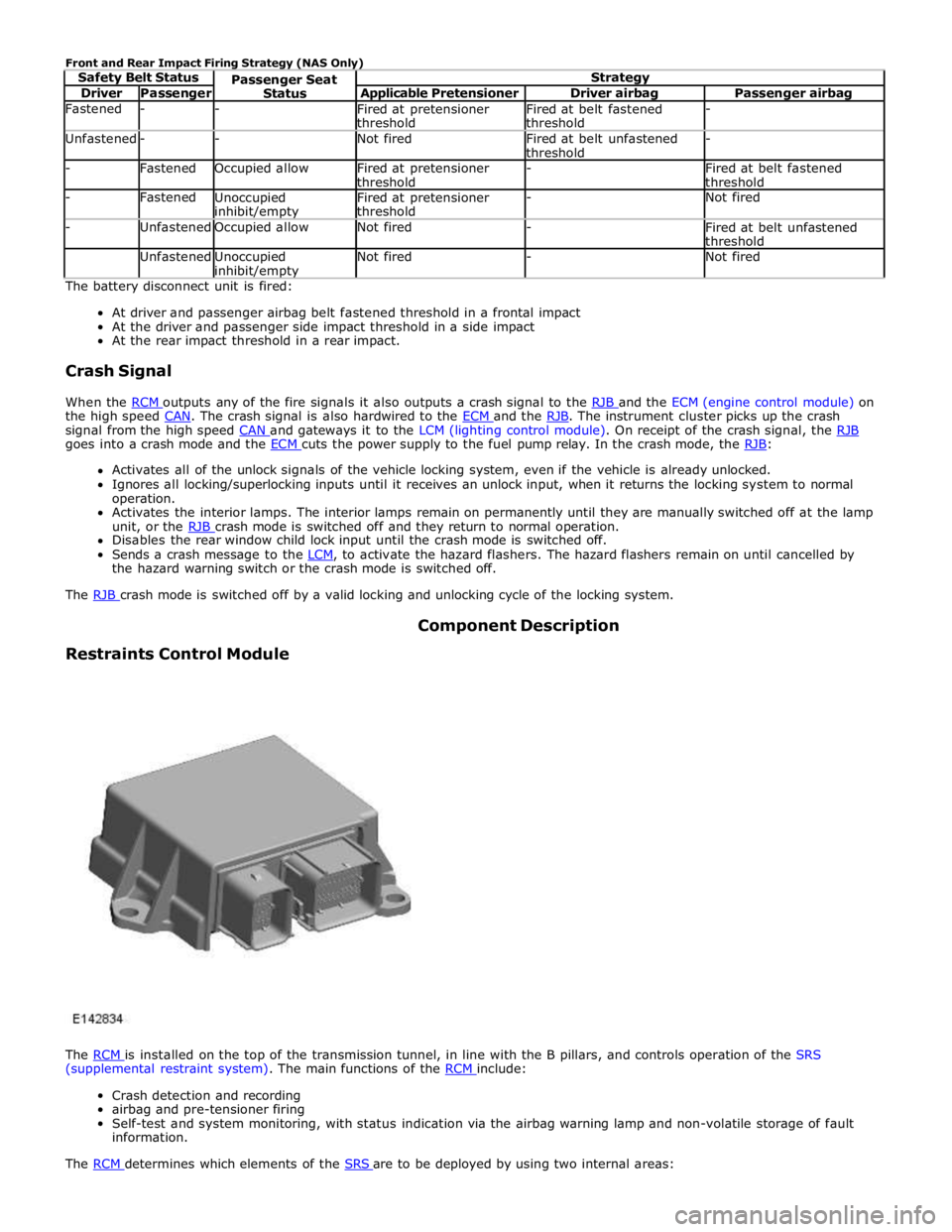
Driver Passenger Applicable Pretensioner Driver airbag Passenger airbag Fastened - -
Fired at pretensioner
threshold Fired at belt fastened
threshold - Unfastened - - Not fired
Fired at belt unfastened
threshold - - Fastened Occupied allow
Fired at pretensioner
threshold -
Fired at belt fastened
threshold - Fastened
Unoccupied inhibit/empty Fired at pretensioner
threshold - Not fired - Unfastened Occupied allow Not fired -
Fired at belt unfastened
threshold Unfastened
Unoccupied inhibit/empty Not fired - Not fired The battery disconnect unit is fired:
At driver and passenger airbag belt fastened threshold in a frontal impact
At the driver and passenger side impact threshold in a side impact
At the rear impact threshold in a rear impact.
Crash Signal
When the RCM outputs any of the fire signals it also outputs a crash signal to the RJB and the ECM (engine control module) on the high speed CAN. The crash signal is also hardwired to the ECM and the RJB. The instrument cluster picks up the crash signal from the high speed CAN and gateways it to the LCM (lighting control module). On receipt of the crash signal, the RJB goes into a crash mode and the ECM cuts the power supply to the fuel pump relay. In the crash mode, the RJB: Activates all of the unlock signals of the vehicle locking system, even if the vehicle is already unlocked.
Ignores all locking/superlocking inputs until it receives an unlock input, when it returns the locking system to normal
operation.
Activates the interior lamps. The interior lamps remain on permanently until they are manually switched off at the lamp
unit, or the RJB crash mode is switched off and they return to normal operation. Disables the rear window child lock input until the crash mode is switched off.
Sends a crash message to the LCM, to activate the hazard flashers. The hazard flashers remain on until cancelled by the hazard warning switch or the crash mode is switched off.
The RJB crash mode is switched off by a valid locking and unlocking cycle of the locking system.
Restraints Control Module Component Description
The RCM is installed on the top of the transmission tunnel, in line with the B pillars, and controls operation of the SRS (supplemental restraint system). The main functions of the RCM include:
Crash detection and recording
airbag and pre-tensioner firing
Self-test and system monitoring, with status indication via the airbag warning lamp and non-volatile storage of fault
information.
The RCM determines which elements of the SRS are to be deployed by using two internal areas:
Page 2616 of 3039
and the safety belt buckle sensor. Based on this data, the RCM decides which level of airbag module deployment is required and forwards the information to the second area, the deployment handler.
The deployment handler evaluates the status of the seat track position sensor and safety belt buckle sensors before a decision
is made about which restraints should finally be deployed.
Data from the side crash sensors is used by the RCM in conjunction with acceleration data from the RCM internal accelerometer to make a deployment decision. The RCM processes the acceleration data and subject to an impact being of high enough severity, decides whether the side airbag module should be deployed.
On board testing of the airbag modules, front safety belt pretensioner firing circuits, warning indicator circuits and module
status (the crash and side impact sensors perform basic self-tests) is performed by the RCM together with the storing of fault codes.
The RCM drives the SRS indicator on the instrument pack via a CAN signal. If the warning lamp fails, a fault code is recorded and a warning tone is sounded in place of the lamp if a further fault occurs. It also provides a temporary back-up power supply
to operate the airbag modules in the event that in crash conditions, the battery supply is lost. In the event of a crash, it
records certain data which can be accessed via the diagnostic connector.
A safing sensor in the RCM provides confirmation of an impact to verify if airbag and pretensioner activation is necessary. A roll-over sensor monitors the lateral attitude of the vehicle. Various firing strategies are employed by the RCM to ensure that during an accident only the appropriate airbags and pretensioners are fired. The firing strategy used also depends on the
inputs from the safety belt switches and the occupant monitoring system.
An energy reserve in the RCM ensures there is always a minimum of 150 milliseconds of stored energy available if the power supply from the ignition switch is disrupted during a crash. The stored energy is sufficient to produce firing signals for the
driver airbag, the passenger airbag and the safety belt pretensioners.
When the ignition is switched on, the RCM performs a self-test and then performs cyclical monitoring of the system. If a fault is detected the RCM stores a related fault code and illuminates the airbag warning indicator. The faults can be retrieved by the recommended Jaguar diagnostic tool over the CAN bus. If a fault that could cause a false fire signal is detected, the RCM disables the respective firing circuit, and keeps it disabled during a crash event.
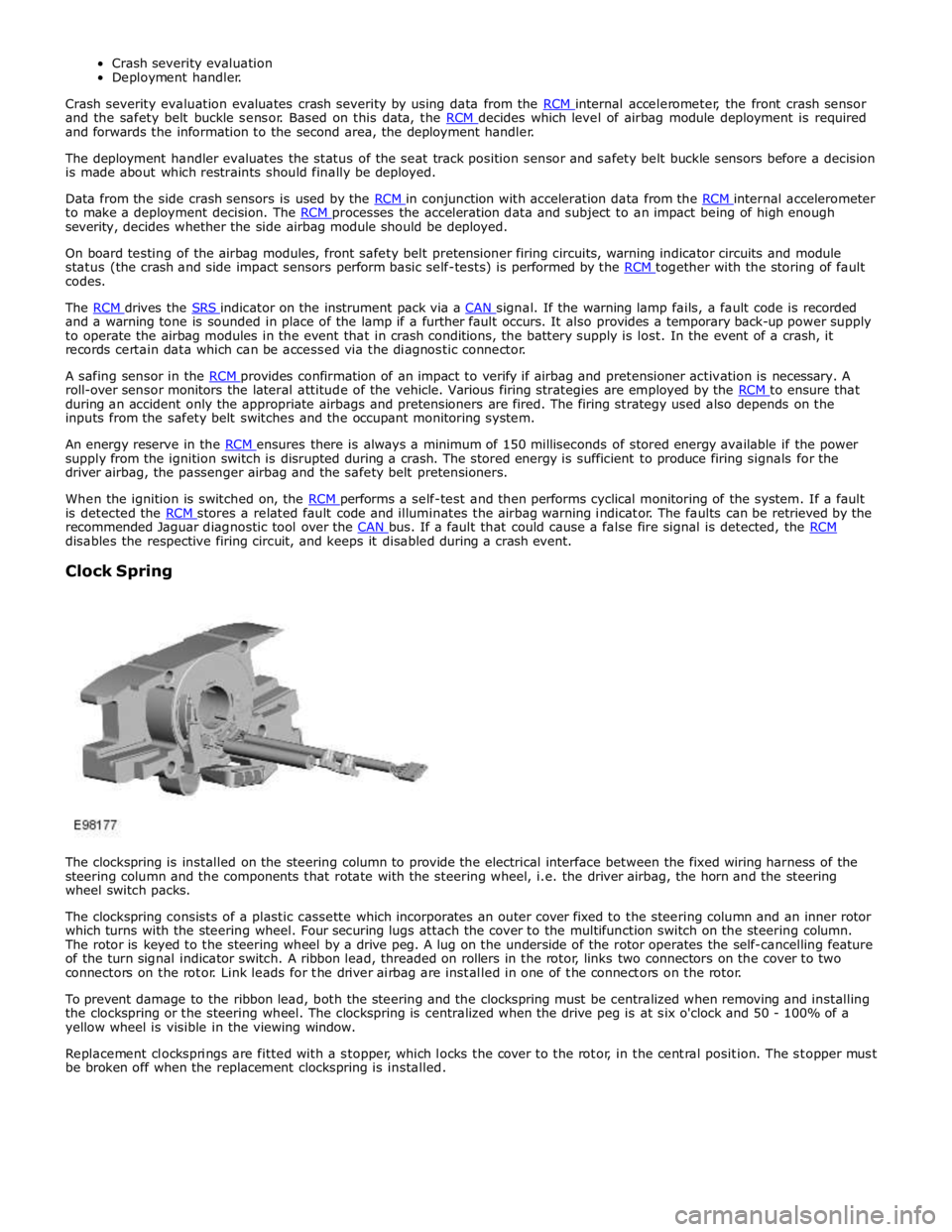
Clock Spring
The clockspring is installed on the steering column to provide the electrical interface between the fixed wiring harness of the
steering column and the components that rotate with the steering wheel, i.e. the driver airbag, the horn and the steering
wheel switch packs.
The clockspring consists of a plastic cassette which incorporates an outer cover fixed to the steering column and an inner rotor
which turns with the steering wheel. Four securing lugs attach the cover to the multifunction switch on the steering column.
The rotor is keyed to the steering wheel by a drive peg. A lug on the underside of the rotor operates the self-cancelling feature
of the turn signal indicator switch. A ribbon lead, threaded on rollers in the rotor, links two connectors on the cover to two
connectors on the rotor. Link leads for the driver airbag are installed in one of the connectors on the rotor.
To prevent damage to the ribbon lead, both the steering and the clockspring must be centralized when removing and installing
the clockspring or the steering wheel. The clockspring is centralized when the drive peg is at six o'clock and 50 - 100% of a
yellow wheel is visible in the viewing window.
Replacement clocksprings are fitted with a stopper, which locks the cover to the rotor, in the central position. The stopper must
be broken off when the replacement clockspring is installed.
Page 2626 of 3039
Do not place the driver or passenger air bag module with the trim
cover or deployment door facing down, as the forces of the deploying air
bag can cause it to ricochet and cause personal injury. Failure to follow
this instruction may result in personal injury.
Equipment required: Universal deployment tool-Part N° 418-135 and 12V
Battery.
2. The deployment procedure should be carried out outdoors away from
other personnel.
3. Remove any loose debris from around air bag. Make sure that no
flammable liquids are present.
4. Disconnect the battery ground and positive cables.
5. Disconnect the relevant air bag module electrical connector.
6. Connect the appropriate adaptor lead to the restraint device.
7. Connect the deployment lead to the adaptor lead. Pass wire of the
deployment tool through window, close all doors, leave window with lead
for deployment tool open.
8. WARNING: Before proceeding, make sure precautions have been taken
to warn personnel of a possible loud noise upon activation. Do not allow
anybody to approach closer to restraint device than six meters. Failure
to follow this instruction may result in personal injury.
Move as far from restraint device as possible and connect the tool clips
to a 12V vehicle battery.
9. WARNING: Do not handle the deployed device immediately after
activation - it may be hot. Allow the unit to cool for at least 20 minutes.
Cooling modules should be continuously monitored to make sure heat
does not create a fire with spilled liquids or other debris. Failure to
follow this instruction may result in personal injury.
Deploy the module by depressing both switches on the tool. If activation
does not occur, disconnect battery from tool and seek advise from Jaguar
Engineering and wait for further instructions.
10. Repeat procedure for all air bags in vehicle.
11. The vehicle is now to be scrapped in the normal manner with modules
installed.
Disposal of live air bag modules for all air bags, using tyres
1. Equipment required: Deployment tool 418-S135, Battery (12V), Safety
goggles to BS2092 grade 2, Rubber gloves to PrEN 374 class 2, Ear
protectors that have been measured to BS.EN 24869, Particulate
respirator to EN 149 grade FFP2S
2. The deployment procedure should be carried out outdoors, away from
other personnel.
3. Stack four scrap tyres, securing together with heavy gauge wire or cable.
Page 2710 of 3039
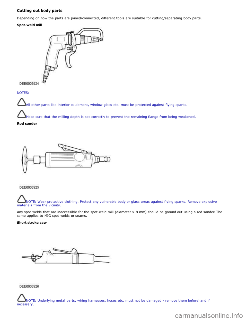
Cutting out body parts
Depending on how the parts are joined/connected, different tools are suitable for cutting/separating body parts.
NOTES:
All other parts like interior equipment, window glass etc. must be protected against flying sparks.
Make sure that the milling depth is set correctly to prevent the remaining flange from being weakened.
Rod sander
NOTE: Wear protective clothing. Protect any vulnerable body or glass areas against flying sparks. Remove explosive
materials from the vicinity.
Any spot welds that are inaccessible for the spot-weld mill (diameter > 8 mm) should be ground out using a rod sander. The
same applies to MIG spot welds or seams.
Short stroke saw
NOTE: Underlying metal parts, wiring harnesses, hoses etc. must not be damaged - remove them beforehand if
necessary. Spot-weld mill
Page 2715 of 3039
MIG/MAG welding
Setting up the equipment and co-ordinating the welding parameters.
Any joins that are MIG/MAG welded in production must also be MIG/MAG welded during repairs. Also during repairs,
some resistance spot welds need to be replaced by plug welds.
If access is difficult, or if a suitably powerful spot welder (see above) for total panel thicknesses of 3 mm or more is
not available, resistance spot welding must be partially replaced by plug welding during repairs. In this case, the
increased time needed and the correspondingly more demanding corrosion protection requirements, must be taken into
account.
Welding repairs can only be carried out properly if the equipment is set up correctly and all the welding parameters are
co-ordinated.
Equipment:
- Set up the equipment as directed by the manufacturer.
- The hoses must be untwisted.
- The core must be free of abraded rod particles.
- The gas and current nozzles must be free of slag and scale residue.
- Pay attention to the quality of the welding rod and the throughput of gas.
Body:
- Make sure that the joint surface is perfect.
- Prepare a bare metal joint surface.
- Maintain the correct gaps (formation of roots).
Notes on technique/method:
NOTES:
The increased application of heat during MIG welding destroys the welding primer/zinc layer over a much larger
area than during resistance spot welding, as a result of which much more care needs to be taken when applying
anti-corrosion protection afterwards.
A test weld should always be carried out to make sure that the welded joint is not just a surface connection.
- Attach the ground cable right next to the welding point (Make sure that good contact is made).
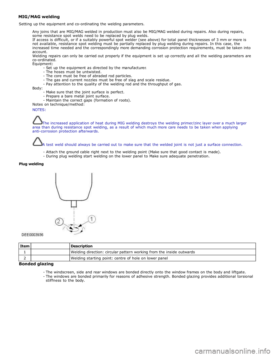
- During plug welding start welding on the lower panel to Make sure adequate penetration.
Plug welding
Item
Description 1
Welding direction: circular pattern working from the inside outwards 2
Welding starting point: centre of hole on lower panel Bonded glazing
- The windscreen, side and rear windows are bonded directly onto the window frames on the body and liftgate.
- The windows are bonded primarily for reasons of adhesive strength. Bonded glazing provides additional torsional
stiffness to the body.
Page 2716 of 3039
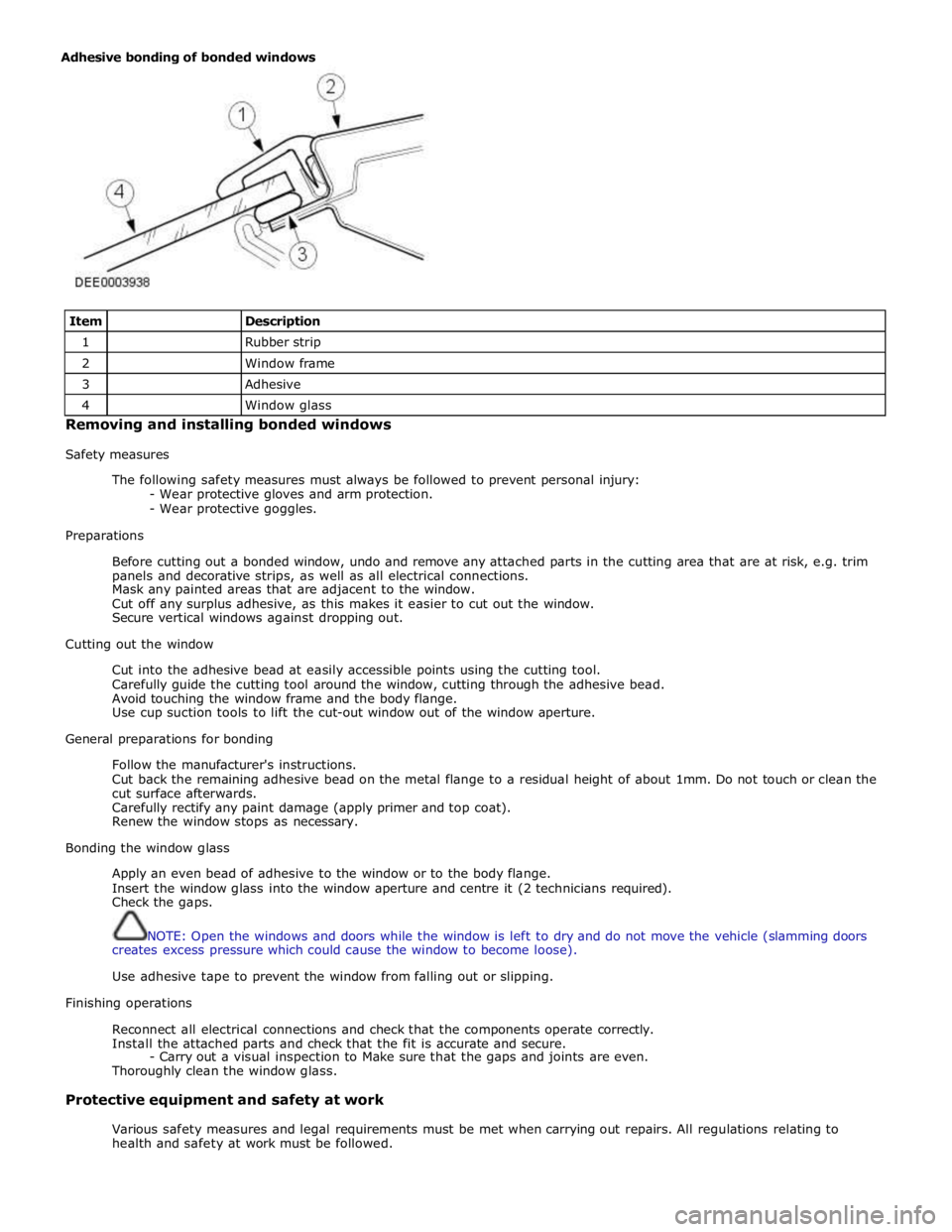
Item
Description 1
Rubber strip 2
Window frame 3
Adhesive 4
Window glass Removing and installing bonded windows
Safety measures
The following safety measures must always be followed to prevent personal injury:
- Wear protective gloves and arm protection.
- Wear protective goggles.
Preparations
Before cutting out a bonded window, undo and remove any attached parts in the cutting area that are at risk, e.g. trim
panels and decorative strips, as well as all electrical connections.
Mask any painted areas that are adjacent to the window.
Cut off any surplus adhesive, as this makes it easier to cut out the window.
Secure vertical windows against dropping out.
Cutting out the window
Cut into the adhesive bead at easily accessible points using the cutting tool.
Carefully guide the cutting tool around the window, cutting through the adhesive bead.
Avoid touching the window frame and the body flange.
Use cup suction tools to lift the cut-out window out of the window aperture.
General preparations for bonding
Follow the manufacturer's instructions.
Cut back the remaining adhesive bead on the metal flange to a residual height of about 1mm. Do not touch or clean the
cut surface afterwards.
Carefully rectify any paint damage (apply primer and top coat).
Renew the window stops as necessary.
Bonding the window glass
Apply an even bead of adhesive to the window or to the body flange.
Insert the window glass into the window aperture and centre it (2 technicians required).
Check the gaps.
NOTE: Open the windows and doors while the window is left to dry and do not move the vehicle (slamming doors
creates excess pressure which could cause the window to become loose).
Use adhesive tape to prevent the window from falling out or slipping.
Finishing operations
Reconnect all electrical connections and check that the components operate correctly.
Install the attached parts and check that the fit is accurate and secure.
- Carry out a visual inspection to Make sure that the gaps and joints are even.
Thoroughly clean the window glass.
Protective equipment and safety at work
Various safety measures and legal requirements must be met when carrying out repairs. All regulations relating to
health and safety at work must be followed. Adhesive bonding of bonded windows