2010 INFINITI QX56 check engine
[x] Cancel search: check enginePage 2837 of 4210

MWI
BCM (BODY CONTROL MODULE)MWI-75
< ECU DIAGNOSIS >
C
DE
F
G H
I
J
K L
M B A
O P
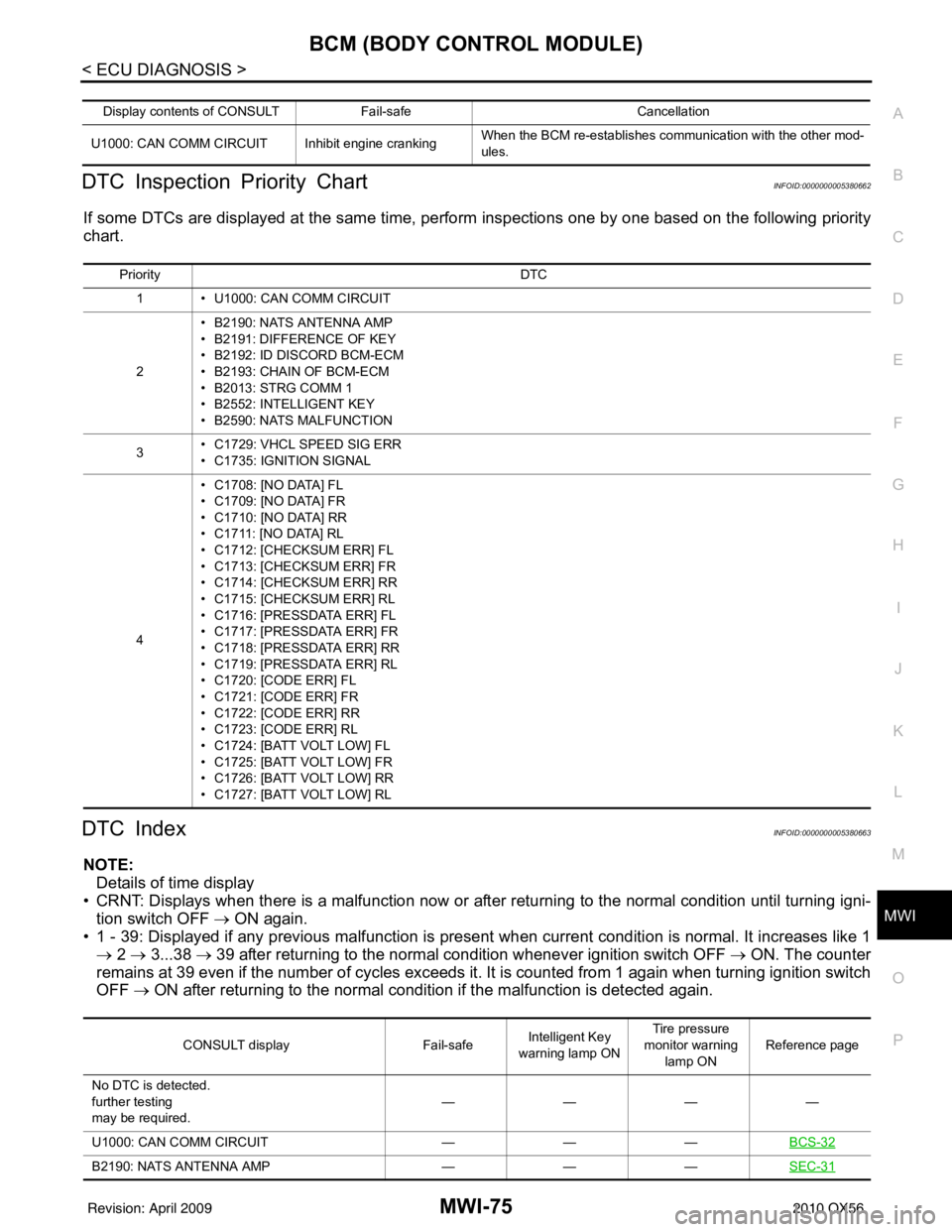
DTC Inspection Priority ChartINFOID:0000000005380662
If some DTCs are displayed at the same time, perform inspections one by one based on the following priority
chart.
DTC IndexINFOID:0000000005380663
NOTE: Details of time display
• CRNT: Displays when there is a malfunction now or after returning to the normal condition until turning igni- tion switch OFF → ON again.
• 1 - 39: Displayed if any previous ma lfunction is present when current conditi on is normal. It increases like 1
→ 2 → 3...38 → 39 after returning to the normal condition whenever ignition switch OFF → ON. The counter
remains at 39 even if the number of cycles exceeds it. It is counted from 1 again when turning ignition switch
OFF → ON after returning to the normal condi tion if the malfunction is detected again.
Display contents of CONSULT Fail-safe Cancellation
U1000: CAN COMM CIRCUIT I nhibit engine crankingWhen the BCM re-establishes communication with the other mod-
ules.
Priority
DTC
1 • U1000: CAN COMM CIRCUIT
2 • B2190: NATS ANTENNA AMP
• B2191: DIFFERENCE OF KEY
• B2192: ID DISCORD BCM-ECM
• B2193: CHAIN OF BCM-ECM
• B2013: STRG COMM 1
• B2552: INTELLIGENT KEY
• B2590: NATS MALFUNCTION
3 • C1729: VHCL SPEED SIG ERR
• C1735: IGNITION SIGNAL
4 • C1708: [NO DATA] FL
• C1709: [NO DATA] FR
• C1710: [NO DATA] RR
• C1711: [NO DATA] RL
• C1712: [CHECKSUM ERR] FL
• C1713: [CHECKSUM ERR] FR
• C1714: [CHECKSUM ERR] RR
• C1715: [CHECKSUM ERR] RL
• C1716: [PRESSDATA ERR] FL
• C1717: [PRESSDATA ERR] FR
• C1718: [PRESSDATA ERR] RR
• C1719: [PRESSDATA ERR] RL
• C1720: [CODE ERR] FL
• C1721: [CODE ERR] FR
• C1722: [CODE ERR] RR
• C1723: [CODE ERR] RL
• C1724: [BATT VOLT LOW] FL
• C1725: [BATT VOLT LOW] FR
• C1726: [BATT VOLT LOW] RR
• C1727: [BATT VOLT LOW] RL
CONSULT display
Fail-safeIntelligent Key
warning lamp ON Tire pressure
monitor warning lamp ON Reference page
No DTC is detected.
further testing
may be required. ————
U1000: CAN COMM CIRCUIT ———BCS-32
B2190: NATS ANTENNA AMP ———SEC-31
Revision: April 20092010 QX56
Page 2856 of 4210

MWI-94
< SYMPTOM DIAGNOSIS >
THE OIL PRESSURE WARNING LAMP DOES NOT TURN OFF
THE OIL PRESSURE WARNING LA MP DOES NOT TURN OFF
DescriptionINFOID:0000000005146121
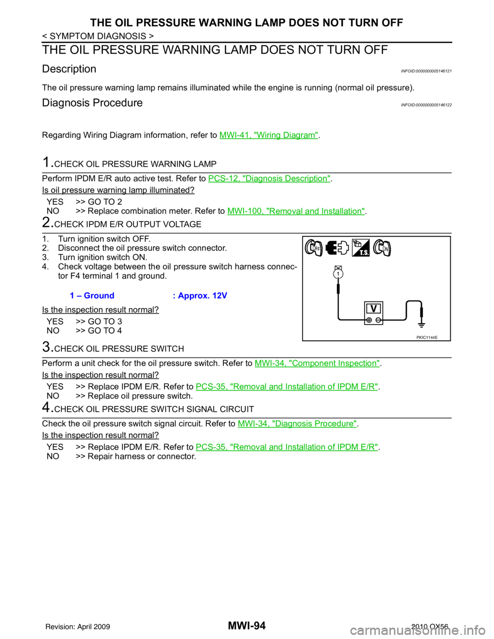
The oil pressure warning lamp remains illuminated while the engine is running (normal oil pressure).
Diagnosis ProcedureINFOID:0000000005146122
Regarding Wiring Diagram information, refer to MWI-41, "Wiring Diagram".
1.CHECK OIL PRESSURE WARNING LAMP
Perform IPDM E/R auto active test. Refer to PCS-12, "
Diagnosis Description".
Is oil pressure warning lamp illuminated?
YES >> GO TO 2
NO >> Replace combination meter. Refer to MWI-100, "
Removal and Installation".
2.CHECK IPDM E/R OUTPUT VOLTAGE
1. Turn ignition switch OFF.
2. Disconnect the oil pressure switch connector.
3. Turn ignition switch ON.
4. Check voltage between the oil pressure switch harness connec- tor F4 terminal 1 and ground.
Is the inspection result normal?
YES >> GO TO 3
NO >> GO TO 4
3.CHECK OIL PRESSURE SWITCH
Perform a unit check for the oil pressure switch. Refer to MWI-34, "
Component Inspection".
Is the inspection result normal?
YES >> Replace IPDM E/R. Refer to PCS-35, "Removal and Installation of IPDM E/R".
NO >> Replace oil pressure switch.
4.CHECK OIL PRESSURE SWITCH SIGNAL CIRCUIT
Check the oil pressure switch signal circuit. Refer to MWI-34, "
Diagnosis Procedure".
Is the inspection result normal?
YES >> Replace IPDM E/R. Refer to PCS-35, "Removal and Installation of IPDM E/R".
NO >> Repair harness or connector. 1 – Ground
: Approx. 12V
PKIC1144E
Revision: April 20092010 QX56
Page 2857 of 4210

MWI
THE PARKING BRAKE RELEASE WARNING CONTINUES DISPLAYING, OR
DOES NOT DISPLAY
MWI-95
< SYMPTOM DIAGNOSIS >
C
DE
F
G H
I
J
K L
M B A
O P
THE PARKING BRAKE RELEASE WA RNING CONTINUES DISPLAYING,
OR DOES NOT DISPLAY
DescriptionINFOID:0000000005146123
• The parking brake warning is displayed while driving the vehicle even though the parking brake is released.
• The parking brake warning is not displayed even t hough driving the vehicle with the parking brake applied.
Diagnosis ProcedureINFOID:0000000005146124
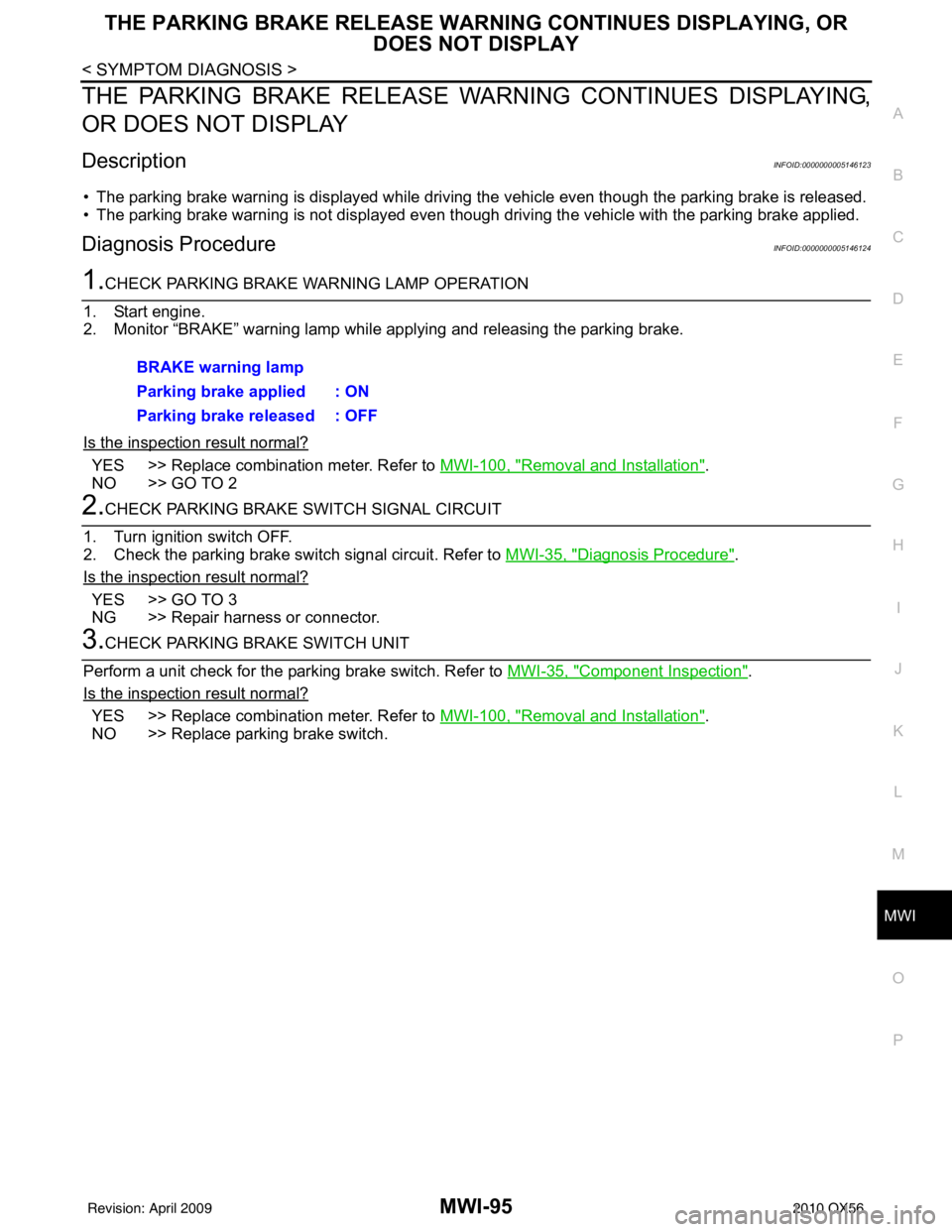
1.CHECK PARKING BRAKE WARNING LAMP OPERATION
1. Start engine.
2. Monitor “BRAKE” warning lamp while applying and releasing the parking brake.
Is the inspection result normal?
YES >> Replace combination meter. Refer to MWI-100, "Removal and Installation".
NO >> GO TO 2
2.CHECK PARKING BRAKE SWITCH SIGNAL CIRCUIT
1. Turn ignition switch OFF.
2. Check the parking brake switch signal circuit. Refer to MWI-35, "
Diagnosis Procedure".
Is the inspection result normal?
YES >> GO TO 3
NG >> Repair harness or connector.
3.CHECK PARKING BRAKE SWITCH UNIT
Perform a unit check for the parking brake switch. Refer to MWI-35, "
Component Inspection".
Is the inspection result normal?
YES >> Replace combination meter. Refer to MWI-100, "Removal and Installation".
NO >> Replace parking brake switch. BRAKE warning lamp
Parking brake applied : ON
Parking brake released : OFF
Revision: April 20092010 QX56
Page 2887 of 4210
![INFINITI QX56 2010 Factory Service Manual PCS-12
< FUNCTION DIAGNOSIS >[IPDM E/R]
DIAGNOSIS SYSTEM (IPDM E/R)
DIAGNOSIS SYSTEM (IPDM E/R)
Diagnosis DescriptionINFOID:0000000005146506
AUTO ACTIVE TEST
Description
In auto active test mode, the INFINITI QX56 2010 Factory Service Manual PCS-12
< FUNCTION DIAGNOSIS >[IPDM E/R]
DIAGNOSIS SYSTEM (IPDM E/R)
DIAGNOSIS SYSTEM (IPDM E/R)
Diagnosis DescriptionINFOID:0000000005146506
AUTO ACTIVE TEST
Description
In auto active test mode, the](/manual-img/42/57032/w960_57032-2886.png)
PCS-12
< FUNCTION DIAGNOSIS >[IPDM E/R]
DIAGNOSIS SYSTEM (IPDM E/R)
DIAGNOSIS SYSTEM (IPDM E/R)
Diagnosis DescriptionINFOID:0000000005146506
AUTO ACTIVE TEST
Description
In auto active test mode, the IPDM
E/R sends a drive signal to the follo wing systems to check their operation.
• Oil pressure low/coolant pressure high warning indicator
• Oil pressure gauge
• Rear window defogger
• Front wipers
• Tail, license and parking lamps
• Front fog lamps
• Headlamps (Hi, Lo)
• A/C compressor (magnetic clutch)
• Cooling fan
Operation Procedure
1. Close the hood and front door RH, and lift the wiper a rms from the windshield (to prevent windshield dam-
age due to wiper operation).
NOTE:
When auto active test is performed with hood opened, sprinkle water on windshield before hand.
2. Turn ignition switch OFF.
3. Turn the ignition switch ON and, within 20 seconds, press the front door switch LH 10 times. Then turn the ignition switch OFF.
4. Turn the ignition switch ON within 10 seconds. Af ter that the horn sounds once and the auto active test
starts.
5. After a series of the following operations is repeated 3 times, auto active test is completed.
NOTE:
When auto active test mode has to be cancelled halfway through test, turn ignition switch OFF.
CAUTION:
• If auto active test mode cannot be actuated, check door switch system. Refer to DLK-71, "
Descrip-
tion".
• Do not start the engine.
Inspection in Auto Active Test Mode
When auto active test mode is actuated, the following 7 steps are repeated 3 times.
Operation
sequence Inspection Location
Operation
1 Rear window defogger 10 seconds
2 Front wipers LO for 5 seconds → HI for 5 seconds
WKIA4655E
Revision: April 20092010 QX56
Page 2913 of 4210

PG
PRECAUTIONSPG-3
< PRECAUTION >
C
DE
F
G H
I
J
K L
B A
O P
N
5. When the repair work is completed, return the ignition switch to the
″LOCK ″ position before connecting
the battery cables. (At this time, the steering lock mechanism will engage.)
6. Perform a self-diagnosis check of al l control units using CONSULT-III.
Precaution for Power Generation Variable Voltage Control SystemINFOID:0000000005146570
CAUTION:
For this model, the battery current sensor that is installed to the negative battery cable measures the
charging/discharging current of the battery and performs various engine controls. If an electrical com-
ponent is connected directly to the negative battery terminal, the current flowing through that compo-
nent will not be measured by the battery current sensor. This condition may cause a malfunction of
the engine control system and battery discharge m ay occur. Do not connect an electrical component
or ground wire directly to the battery terminal.
Revision: April 20092010 QX56
Page 2915 of 4210

PG
BATTERYPG-5
< BASIC INSPECTION >
C
DE
F
G H
I
J
K L
B A
O P
N
BASIC INSPECTION
BATTERY
How to Handle BatteryINFOID:0000000005146573
CAUTION:
• If it becomes necessary to start the engine with
a booster battery and jumper cables, use a 12-volt
booster battery.
• After connecting battery cables, ensure that they are tightly clamped to battery terminals for good
contact.
• Never add distilled water through the hole used to check specific gravity.
METHODS OF PREVENTING OVER-DISCHARGE
The following precautions must be taken to prevent over-discharging a battery.
• The battery surface (particularly its top) should always be kept
clean and dry.
• The terminal connections should be clean and tight.
• At every routine maintenance, check the electrolyte level. This also applies to batteries designated as “low maintenance” and
“maintenance-free”.
• When the vehicle is not going to be used over a long period of time, disconnect the battery cable from the negative terminal. (If
the vehicle has an extended storage switch, turn it off.)
• Check the charge condition of the battery. Periodically check the specific gr avity of the electrolyte. Keep a
close check on charge condition to prevent over-discharge.
CHECKING ELECTROLYTE LEVEL
WARNING:
Never allow battery fluid to come in contact with skin, eyes, fabrics, or painted surfaces. After touch-
ing a battery, never touch or rub your eyes until you have thoroughly washed your hands. If acid con-
tacts eyes, skin or clothing, imme diately flush with water for 15 minutes and seek medical attention.
MEL040F
ELA0349D
MEL042F
Revision: April 20092010 QX56
Page 3080 of 4210

BCM (BODY CONTROL MODULE)PWC-95
< ECU DIAGNOSIS >
C
DE
F
G H
I
J
L
M A
B
PWC
N
O P
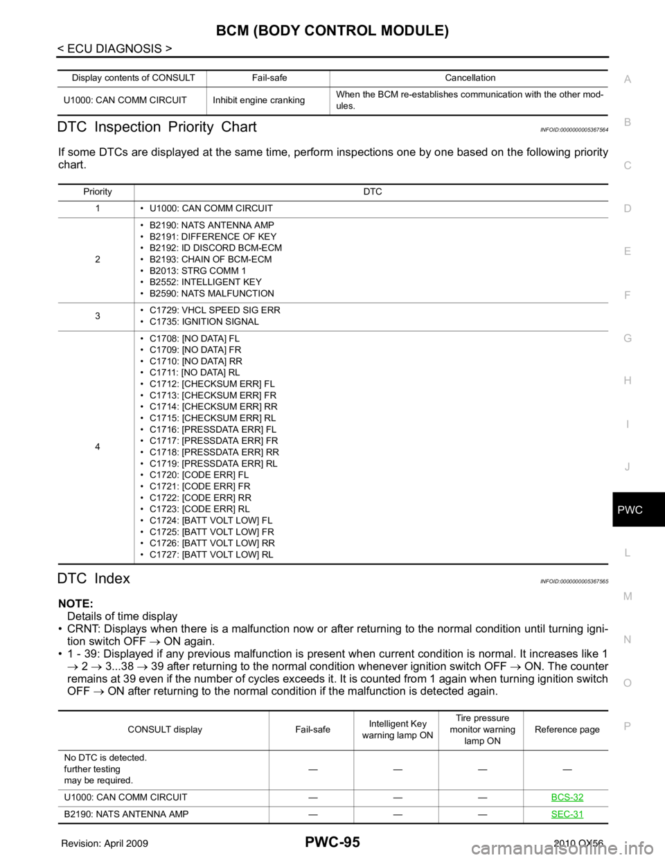
DTC Inspection Priority ChartINFOID:0000000005367564
If some DTCs are displayed at the same time, perform inspections one by one based on the following priority
chart.
DTC IndexINFOID:0000000005367565
NOTE: Details of time display
• CRNT: Displays when there is a malfunction now or after returning to the normal condition until turning igni- tion switch OFF → ON again.
• 1 - 39: Displayed if any previous ma lfunction is present when current conditi on is normal. It increases like 1
→ 2 → 3...38 → 39 after returning to the normal condition whenever ignition switch OFF → ON. The counter
remains at 39 even if the number of cycles exceeds it. It is counted from 1 again when turning ignition switch
OFF → ON after returning to the normal condi tion if the malfunction is detected again.
Display contents of CONSULT Fail-safe Cancellation
U1000: CAN COMM CIRCUIT I nhibit engine crankingWhen the BCM re-establishes communication with the other mod-
ules.
Priority
DTC
1 • U1000: CAN COMM CIRCUIT
2 • B2190: NATS ANTENNA AMP
• B2191: DIFFERENCE OF KEY
• B2192: ID DISCORD BCM-ECM
• B2193: CHAIN OF BCM-ECM
• B2013: STRG COMM 1
• B2552: INTELLIGENT KEY
• B2590: NATS MALFUNCTION
3 • C1729: VHCL SPEED SIG ERR
• C1735: IGNITION SIGNAL
4 • C1708: [NO DATA] FL
• C1709: [NO DATA] FR
• C1710: [NO DATA] RR
• C1711: [NO DATA] RL
• C1712: [CHECKSUM ERR] FL
• C1713: [CHECKSUM ERR] FR
• C1714: [CHECKSUM ERR] RR
• C1715: [CHECKSUM ERR] RL
• C1716: [PRESSDATA ERR] FL
• C1717: [PRESSDATA ERR] FR
• C1718: [PRESSDATA ERR] RR
• C1719: [PRESSDATA ERR] RL
• C1720: [CODE ERR] FL
• C1721: [CODE ERR] FR
• C1722: [CODE ERR] RR
• C1723: [CODE ERR] RL
• C1724: [BATT VOLT LOW] FL
• C1725: [BATT VOLT LOW] FR
• C1726: [BATT VOLT LOW] RR
• C1727: [BATT VOLT LOW] RL
CONSULT display
Fail-safeIntelligent Key
warning lamp ON Tire pressure
monitor warning lamp ON Reference page
No DTC is detected.
further testing
may be required. ————
U1000: CAN COMM CIRCUIT ———BCS-32
B2190: NATS ANTENNA AMP ———SEC-31
Revision: April 20092010 QX56
Page 3159 of 4210

BCM (BODY CONTROL MODULE)RF-31
< ECU DIAGNOSIS >
C
DE
F
G H
I
J
L
M A
B
RF
N
O P
DTC Inspection Priority ChartINFOID:0000000005370302
If some DTCs are displayed at the same time, perform inspections one by one based on the following priority
chart.
DTC IndexINFOID:0000000005370303
NOTE: Details of time display
• CRNT: Displays when there is a malfunction now or after returning to the normal condition until turning igni- tion switch OFF → ON again.
• 1 - 39: Displayed if any previous ma lfunction is present when current conditi on is normal. It increases like 1
→ 2 → 3...38 → 39 after returning to the normal condition whenever ignition switch OFF → ON. The counter
remains at 39 even if the number of cycles exceeds it. It is counted from 1 again when turning ignition switch
OFF → ON after returning to the normal condi tion if the malfunction is detected again.
Display contents of CONSULT Fail-safe Cancellation
U1000: CAN COMM CIRCUIT I nhibit engine crankingWhen the BCM re-establishes communication with the other mod-
ules.
Priority
DTC
1 • U1000: CAN COMM CIRCUIT
2 • B2190: NATS ANTENNA AMP
• B2191: DIFFERENCE OF KEY
• B2192: ID DISCORD BCM-ECM
• B2193: CHAIN OF BCM-ECM
• B2013: STRG COMM 1
• B2552: INTELLIGENT KEY
• B2590: NATS MALFUNCTION
3 • C1729: VHCL SPEED SIG ERR
• C1735: IGNITION SIGNAL
4 • C1708: [NO DATA] FL
• C1709: [NO DATA] FR
• C1710: [NO DATA] RR
• C1711: [NO DATA] RL
• C1712: [CHECKSUM ERR] FL
• C1713: [CHECKSUM ERR] FR
• C1714: [CHECKSUM ERR] RR
• C1715: [CHECKSUM ERR] RL
• C1716: [PRESSDATA ERR] FL
• C1717: [PRESSDATA ERR] FR
• C1718: [PRESSDATA ERR] RR
• C1719: [PRESSDATA ERR] RL
• C1720: [CODE ERR] FL
• C1721: [CODE ERR] FR
• C1722: [CODE ERR] RR
• C1723: [CODE ERR] RL
• C1724: [BATT VOLT LOW] FL
• C1725: [BATT VOLT LOW] FR
• C1726: [BATT VOLT LOW] RR
• C1727: [BATT VOLT LOW] RL
CONSULT display
Fail-safeIntelligent Key
warning lamp ON Tire pressure
monitor warning lamp ON Reference page
No DTC is detected.
further testing
may be required. ————
U1000: CAN COMM CIRCUIT ———BCS-32
B2190: NATS ANTENNA AMP ———SEC-31
Revision: April 20092010 QX56