2010 INFINITI QX56 water pump
[x] Cancel search: water pumpPage 1864 of 4210
DRIVE BELTSEM-13
< ON-VEHICLE MAINTENANCE >
C
DE
F
G H
I
J
K L
M A
EM
NP
O
ON-VEHICLE MAINTENANCE
DRIVE BELTS
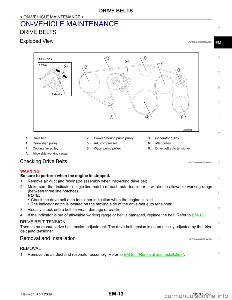
Exploded ViewINFOID:0000000005148974
Checking Drive BeltsINFOID:0000000005148975
WARNING:
Be sure to perform when the engine is stopped.
1. Remove air duct and resonator assembly when inspecting drive belt.
2. Make sure that indicator (single line notch) of eac
h auto tensioner is within the allowable working range
(between three line notches).
NOTE:
• Check the drive belt auto tensioner indication when the engine is cold.
• The indicator notch is located on the moving side of the drive belt auto tensioner.
3. Visually check entire belt for wear, damage or cracks.
4. If the indicator is out of allowable working range or belt is damaged, replace the belt. Refer to EM-13
.
DRIVE BELT TENSION
There is no manual drive belt tension adjustment. The driv e belt tension is automatically adjusted by the drive
belt auto tensioner.
Removal and InstallationINFOID:0000000005148976
REMOVAL
1. Remove the air duct and resonator assembly. Refer to EM-25, "Removal and Installation".
1. Drive belt2. Power steering pump pulley 3. Generator pulley
4. Crankshaft pulley 5. A/C compressor6. Idler pulley
7. Cooling fan pulley 8. Water pump pulley9. Drive belt auto tensioner
A. Allowable working range
LBIA0391E
Revision: April 20092010 QX56
Page 1896 of 4210
TIMING CHAINEM-45
< ON-VEHICLE REPAIR >
C
DE
F
G H
I
J
K L
M A
EM
NP
O
Removal and InstallationINFOID:0000000005149000
NOTE:
• To remove timing chain and associated parts, start with those on the LH bank. The procedure for removing
parts on the RH bank is omitted because it is t he same as that for removal on the LH bank.
• To install timing chain and associated parts, start with those on the RH bank. The procedure for installing parts on the LH bank is omitted because it is t he same as that for installation on the RH bank.
REMOVAL
1. Remove the engine assembly from the vehicle. Refer to EM-78, "Removal and Installation".
2. Remove the following components and related parts: • Drive belt auto tensioner and idler pulley. Refer to EM-13, "
Removal and Installation".
• Thermostat housing and water hose. Refer to CO-22, "
Removal and Installation".
• Power steering oil pump bracket. Refer to ST-26, "
Removal and Installation".
• Oil pan (lower), (upper) and oil strainer. Refer to EM-33, "
Removal and Installation".
• Rocker cover. Refer to EM-38, "
Removal and Installation".
• Generator and generator bracket. Refer to CHG-21, "
Removal and Installation".
• Water pump. Refer to CO-20, "
Exploded View".
3. Disconnect and remove the camshaft position sensor.
4. Disconnect and remove the intake valve ti ming control position sensor (RH and LH).
5. Disconnect and remove the intake valve timing control solenoid valve (RH and LH).
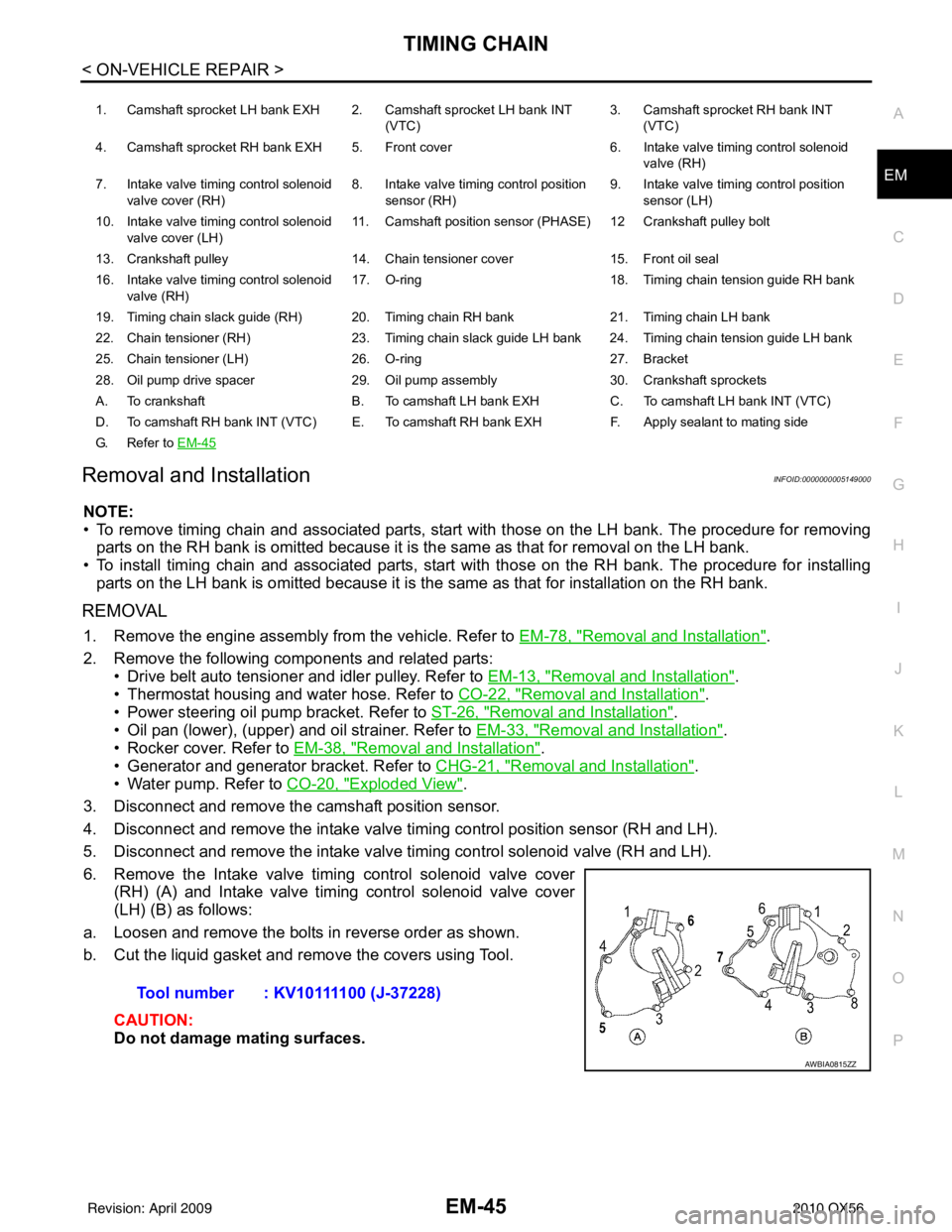
6. Remove the Intake valve timing control solenoid valve cover (RH) (A) and Intake valve timing control solenoid valve cover
(LH) (B) as follows:
a. Loosen and remove the bolts in reverse order as shown.
b. Cut the liquid gasket and remove the covers using Tool.
CAUTION:
Do not damage mating surfaces.
1. Camshaft sprocket LH bank EXH 2. Camshaft sprocket LH bank INT (VTC)3. Camshaft sprocket RH bank INT
(VTC)
4. Camshaft sprocket RH bank EXH 5. Front cover 6. Intake valve timing control solenoid
valve (RH)
7. Intake valve timing control solenoid valve cover (RH) 8. Intake valve timing control position
sensor (RH) 9. Intake valve timing control position
sensor (LH)
10. Intake valve timing control solenoid valve cover (LH) 11. Camshaft position
sensor (PHASE) 12 Cran kshaft pulley bolt
13. Crankshaft pulley 14. Chain tensioner cover 15. Front oil seal
16. Intake valve timing control solenoid valve (RH) 17. O-ring
18. Timing chain tension guide RH bank
19. Timing chain slack guide (RH) 20. Timing chain RH bank 21. Timing chain LH bank
22. Chain tensioner (RH) 23. Timing chain slack guide LH bank 24. Timing chain tension guide LH bank
25. Chain tensioner (LH) 26. O-ring 27. Bracket
28. Oil pump drive spacer 29. Oil pump assembly 30. Crankshaft sprockets
A. To crankshaft B. To camshaft LH bank EXH C. To camshaft LH bank INT (VTC)
D. To camshaft RH bank INT (VTC) E. To camshaft RH bank EXH F. Apply sealant to mating side
G. Refer to EM-45
Tool number : KV10111100 (J-37228)
AWBIA0815ZZ
Revision: April 20092010 QX56
Page 2249 of 4210
GI-26
< PRECAUTION >
PRECAUTIONS
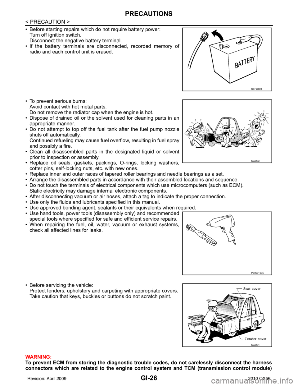
• Before starting repairs which do not require battery power:Turn off ignition switch.
Disconnect the negative battery terminal.
• If the battery terminals are disconnected, recorded memory of radio and each control unit is erased.
• To prevent serious burns: Avoid contact with hot metal parts.
Do not remove the radiator cap when the engine is hot.
• Dispose of drained oil or the solvent used for cleaning parts in an appropriate manner.
• Do not attempt to top off the fuel tank after the fuel pump nozzle
shuts off automatically.
Continued refueling may cause fuel overflow, resulting in fuel spray
and possibly a fire.
• Clean all disassembled parts in the designated liquid or solvent prior to inspection or assembly.
• Replace oil seals, gaskets, packings, O-rings, locking washers,
cotter pins, self-locking nuts, etc. with new ones.
• Replace inner and outer races of tapered roller bearings and needle bearings as a set.
• Arrange the disassembled parts in accordance with their assembled locations and sequence.
• Do not touch the terminals of electrical com ponents which use microcomputers (such as ECM).
Static electricity may damage internal electronic components.
• After disconnecting vacuum or air hoses, atta ch a tag to indicate the proper connection.
• Use only the fluids and lubricants specified in this manual.
• Use approved bonding agent, sealants or their equivalents when required.
• Use hand tools, power tools (disassembly only) and recommended special tools where specified for safe and efficient service repairs.
• When repairing the fuel, oil, water, vacuum or exhaust systems, check all affected lines for leaks.
• Before servicing the vehicle: Protect fenders, upholstery and carpeting with appropriate covers.
Take caution that keys, buckles or buttons do not scratch paint.
WARNING:
To prevent ECM from storing the diagnostic tro uble codes, do not carelessly disconnect the harness
connectors which are related to the engine control system and TCM (transmission control module)
SEF289H
SGI233
PBIC0190E
SGI234
Revision: April 20092010 QX56
Page 2719 of 4210
ENGINE MAINTENANCEMA-15
< ON-VEHICLE MAINTENANCE >
C
DE
F
G H
I
J
K L
M B
MA
N
O A
ENGINE MAINTENANCE
DRIVE BELTS
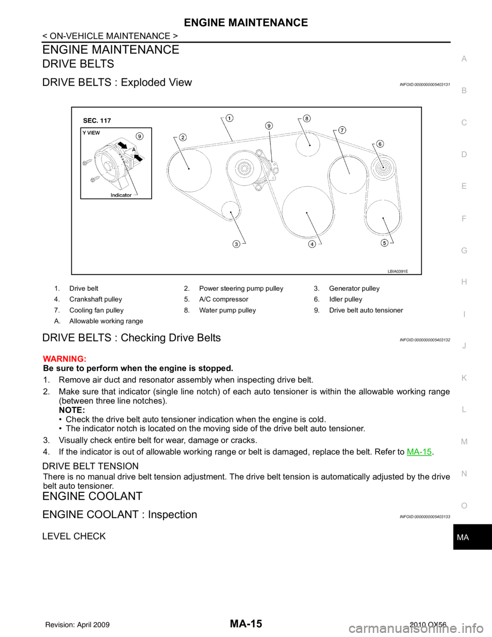
DRIVE BELTS : Exploded ViewINFOID:0000000005403131
DRIVE BELTS : Checking Drive BeltsINFOID:0000000005403132
WARNING:
Be sure to perform when the engine is stopped.
1. Remove air duct and resonator assembly when inspecting drive belt.
2. Make sure that indicator (single line notch) of eac
h auto tensioner is within the allowable working range
(between three line notches).
NOTE:
• Check the drive belt auto tensioner indication when the engine is cold.
• The indicator notch is located on the moving side of the drive belt auto tensioner.
3. Visually check entire belt for wear, damage or cracks.
4. If the indicator is out of allowable working range or belt is damaged, replace the belt. Refer to MA-15
.
DRIVE BELT TENSION
There is no manual drive belt tension adjustment. The driv e belt tension is automatically adjusted by the drive
belt auto tensioner.
ENGINE COOLANT
ENGINE COOLANT : InspectionINFOID:0000000005403133
LEVEL CHECK
1. Drive belt 2. Power steering pump pulley 3. Generator pulley
4. Crankshaft pulley 5. A/C compressor6. Idler pulley
7. Cooling fan pulley 8. Water pump pulley9. Drive belt auto tensioner
A. Allowable working range
LBIA0391E
Revision: April 20092010 QX56
Page 2723 of 4210
ENGINE MAINTENANCEMA-19
< ON-VEHICLE MAINTENANCE >
C
DE
F
G H
I
J
K L
M B
MA
N
O A
9. When the vacuum gauge has reached the specified
amount, disconnect the air hose and wait 20 seconds
to see if the system loses any vacuum. If the vacuum level drops, perform any necessary repairs to the
system and repeat steps 6 - 8 to br ing the vacuum to the specified amount. Recheck for any leaks.
10. Place the coolant container (with the refill hose inserted) at the same level as the top of the radiator. Then
open the ball valve on the refill hose so the coolant will be drawn up to fill the cooling system. The cooling
system is full when the vacuum gauge reads zero.
CAUTION:
Do not allow the coolant container to get too low when filling, to avoid air from being drawn into
the cooling system.
11. Remove the Tool from the radiator neck opening and install the radiator cap.
12. Remove the non-vented reservoir cap.
13. Fill the cooling system reservoir tank to the specified level. Run the engine to warm up the cooling system and top up the system as necessary befor e installing the vented reservoir cap.
FLUSHING COOLING SYSTEM
1. Drain the water from the engine cooling system. Refer to MA-17, "ENGINE COOLANT : Changing Engine
Coolant".
2. Fill the radiator and the reservoir tank (to the “MAX” line), with water. Reinstall the radiator cap and leave
the vented reservoir cap off.
3. Run the engine until it reaches normal operating temperature.
4. Press the engine accelerator two or three times under no-load.
5. Stop the engine and wait until it cools down.
6. Drain the water from the engine cooling system. Refer to MA-17, "
ENGINE COOLANT : Changing Engine
Coolant".
7. Repeat steps 2 through 6 until clear water begins to drain from the radiator.
FUEL LINES
FUEL LINES : Checking Fuel LineINFOID:0000000005403135
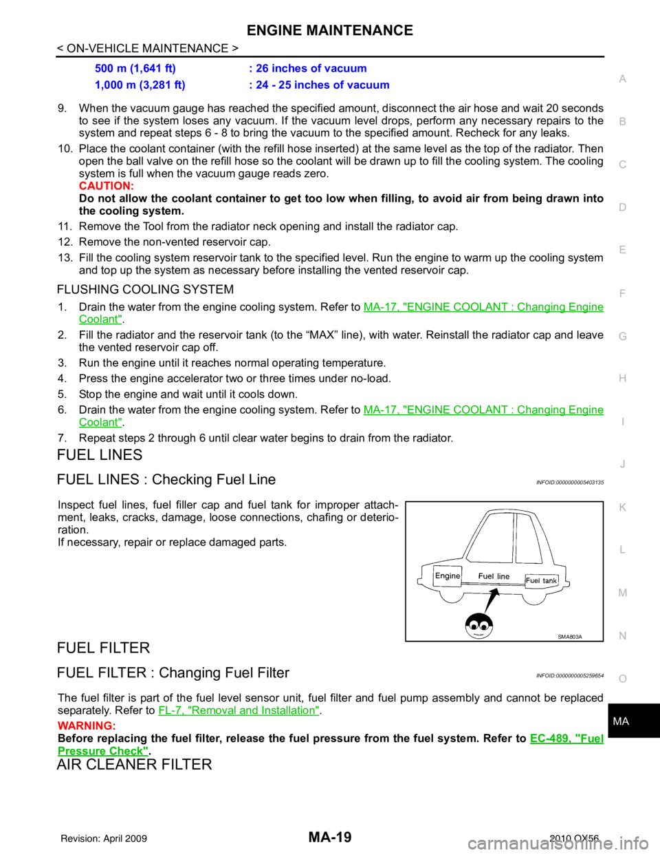
Inspect fuel lines, fuel filler cap and fuel tank for improper attach-
ment, leaks, cracks, damage, loos e connections, chafing or deterio-
ration.
If necessary, repair or replace damaged parts.
FUEL FILTER
FUEL FILTER : Changing Fuel FilterINFOID:0000000005259654
The fuel filter is part of the fuel level sensor unit, fuel filter and fuel pump assembly and cannot be replaced
separately. Refer to FL-7, "
Removal and Installation".
WARNING:
Before replacing the fuel filter, release the fuel pressure from the fuel system. Refer to EC-489, "
Fuel
Pressure Check".
AIR CLEANER FILTER
500 m (1,641 ft): 26 inches of vacuum
1,000 m (3,281 ft) : 24 - 25 inches of vacuum
SMA803A
Revision: April 20092010 QX56