2010 INFINITI QX56 relay
[x] Cancel search: relayPage 3099 of 4210
PWC-114
< SYMPTOM DIAGNOSIS >
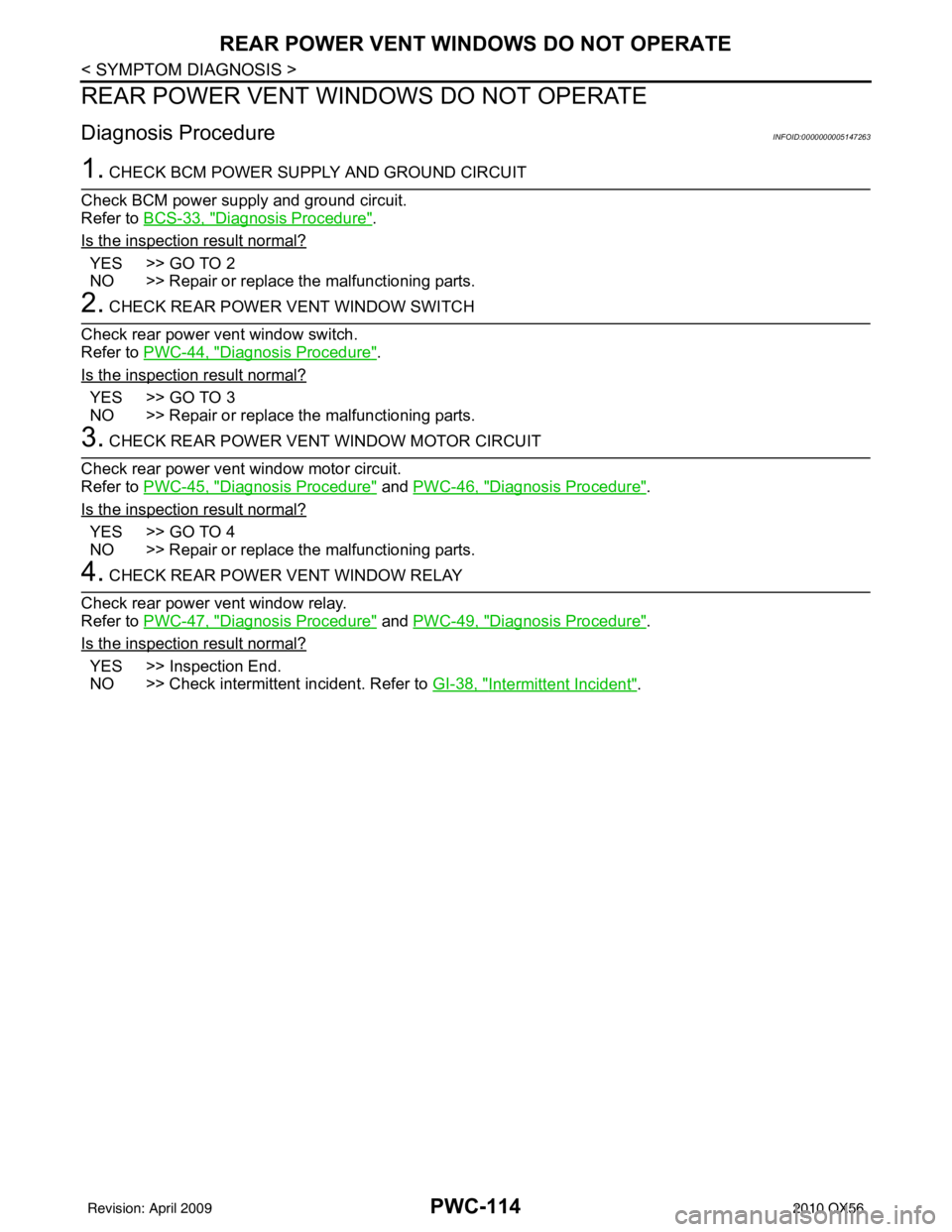
REAR POWER VENT WINDOWS DO NOT OPERATE
REAR POWER VENT WINDOWS DO NOT OPERATE
Diagnosis ProcedureINFOID:0000000005147263
1. CHECK BCM POWER SUPPLY AND GROUND CIRCUIT
Check BCM power supply and ground circuit.
Refer to BCS-33, "
Diagnosis Procedure".
Is the inspection result normal?
YES >> GO TO 2
NO >> Repair or replace the malfunctioning parts.
2. CHECK REAR POWER VENT WINDOW SWITCH
Check rear power vent window switch.
Refer to PWC-44, "
Diagnosis Procedure".
Is the inspection result normal?
YES >> GO TO 3
NO >> Repair or replace the malfunctioning parts.
3. CHECK REAR POWER VENT WINDOW MOTOR CIRCUIT
Check rear power vent window motor circuit.
Refer to PWC-45, "
Diagnosis Procedure" and PWC-46, "Diagnosis Procedure".
Is the inspection result normal?
YES >> GO TO 4
NO >> Repair or replace the malfunctioning parts.
4. CHECK REAR POWER VENT WINDOW RELAY
Check rear power vent window relay.
Refer to PWC-47, "
Diagnosis Procedure" and PWC-49, "Diagnosis Procedure".
Is the inspection result normal?
YES >> Inspection End.
NO >> Check intermittent incident. Refer to GI-38, "
Intermittent Incident".
Revision: April 20092010 QX56
Page 3233 of 4210

SCS-1
SUSPENSION
C
DF
G H
I
J
K L
M
SECTION SCS
A
B
SCS
N
O PCONTENTS
SUSPENSION CONTROL SYSTEM
BASIC INSPECTION ....... .............................3
DIAGNOSIS AND REPAIR WORKFLOW ..... .....3
Work Flow ........................................................... ......3
FUNCTION DIAGNOSIS ...............................5
SUSPENSION CONTROL SYSTEM .............. .....5
System Diagram .................................................. ......5
System Description ...................................................5
Component Parts Location ........................................6
Component Description .............................................6
DIAGNOSIS SYSTEM (SUSPENSION CON-
TROL UNIT) .........................................................
7
CONSULT-III Function ..............................................7
COMPONENT DIAGNOSIS ..........................9
C1801 VEHICLE HEIGHT SENSOR .............. .....9
Description .......................................................... ......9
DTC Logic .................................................................9
Diagnosis Procedure ................................................9
C1802 COMPRESSOR RELAY .........................10
Description ..............................................................10
DTC Logic ...............................................................10
Diagnosis Procedure ..............................................10
C1803 EXHAUST SOLENOID ...........................11
Description ..............................................................11
DTC Logic ...............................................................11
Diagnosis Procedure ..............................................11
C1804 HEIGHT ADJUSTING MALFUNCTION
(COMPRESSOR) ............................................ ....
12
Description .......................................................... ....12
DTC Logic ...............................................................12
Diagnosis Procedure ..............................................12
C1805 HEIGHT ADJUSTING MALFUNCTION
(EXH SOLENOID) ..............................................
13
Description ........................................................... ....13
DTC Logic ................................................................13
Diagnosis Procedure ..............................................13
C1806 VEHICLE HEIGHT SENSOR LOCK-
ING MALFUNCTION .........................................
14
Description ........................................................... ....14
DTC Logic ................................................................14
Diagnosis Procedure ...............................................14
C1807 SENSOR 5V MALFUNCTION ...............15
Description ...............................................................15
DTC Logic ................................................................15
Diagnosis Procedure ..............................................15
C1808 INTEGRAL TIME MALFUNCTION
SUPPLYING AIR ...............................................
16
Description ...............................................................16
DTC Logic ................................................................16
Diagnosis Procedure ..............................................16
POWER SUPPLY AND GROUND CIRCUIT ....17
SUSPENSION CONTROL UNIT ................................17
SUSPENSION CONTROL UNI T : Diagnosis Pro-
cedure .................................................................. ....
17
SUSPENSION AIR COMPRESSOR ..........................17
SUSPENSION AIR COMPRESSOR : Diagnosis
Procedure ............................................................ ....
17
HEIGHT SENSOR .................................................. ....18
HEIGHT SENSOR : Diagnosis Procedure ..............18
COMPRESSOR MOTOR RELAY .....................20
Description ...............................................................20
Component Function Check ....................................20
Diagnosis Procedure ...............................................20
HEIGHT SENSOR SIGNAL CIRCUIT ...............23
Description ...............................................................23
Component Function Check ....................................23
Diagnosis Procedure ...............................................23
Revision: April 20092010 QX56
Page 3237 of 4210
SUSPENSION CONTROL SYSTEMSCS-5
< FUNCTION DIAGNOSIS >
C
DF
G H
I
J
K L
M A
B
SCS
N
O P
FUNCTION DIAGNOSIS
SUSPENSION CONTROL SYSTEM
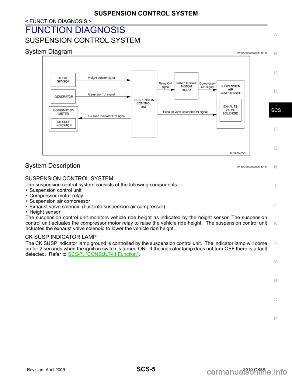
System DiagramINFOID:0000000005148146
System DescriptionINFOID:0000000005148147
SUSPENSION CONTROL SYSTEM
The suspension control system consists of the following components
• Suspension control unit
• Compressor motor relay
• Suspension air compressor
• Exhaust valve solenoid (built into suspension air compressor)
• Height sensor
The suspension control unit monitors vehicle ride height as indicated by the height sensor. The suspension
control unit actuates the compressor motor relay to ra ise the vehicle ride height. The suspension control unit
actuates the exhaust valve solenoid to lower the vehicle ride height.
CK SUSP INDICATOR LAMP
The CK SUSP indicator lamp ground is controlled by the suspension control unit. The indicator lamp will come
on for 2 seconds when the ignition switch is turned ON. If the indicator lamp does not turn OFF there is a fault
detected. Refer to SCS-7, "
CONSULT-III Function".
ALEIA0042GB
Revision: April 20092010 QX56
Page 3238 of 4210
SCS-6
< FUNCTION DIAGNOSIS >
SUSPENSION CONTROL SYSTEM
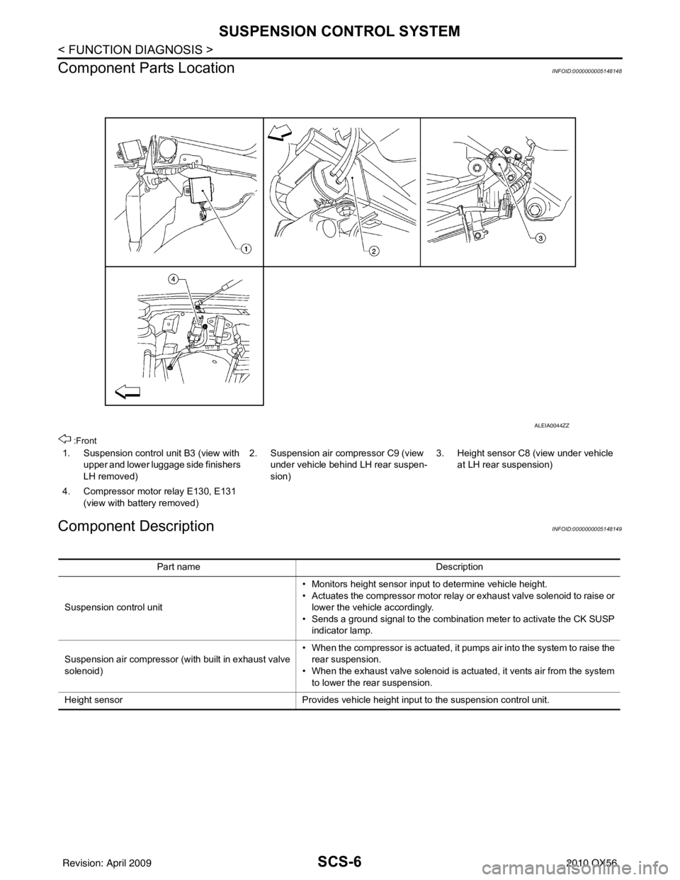
Component Parts Location
INFOID:0000000005148148
:Front
Component DescriptionINFOID:0000000005148149
1. Suspension control unit B3 (view with upper and lower luggage side finishers
LH removed) 2. Suspension air compressor C9 (view
under vehicle behind LH rear suspen-
sion) 3. Height sensor C8 (view under vehicle
at LH rear suspension)
4. Compressor motor relay E130, E131 (view with battery removed)
ALEIA0044ZZ
Part name Description
Suspension control unit • Monitors height sensor input to determine vehicle height.
• Actuates the compressor motor relay or exhaust valve solenoid to raise or
lower the vehicle accordingly.
• Sends a ground signal to the combination meter to activate the CK SUSP indicator lamp.
Suspension air compressor (with built in exhaust valve
solenoid) • When the compressor is actuated, it pumps air into the system to raise the
rear suspension.
• When the exhaust valve solenoid is actuated, it vents air from the system to lower the rear suspension.
Height sensor Provides vehicle height input to the suspension control unit.
Revision: April 20092010 QX56
Page 3242 of 4210
SCS-10
< COMPONENT DIAGNOSIS >
C1802 COMPRESSOR RELAY
C1802 COMPRESSOR RELAY
DescriptionINFOID:0000000005148154
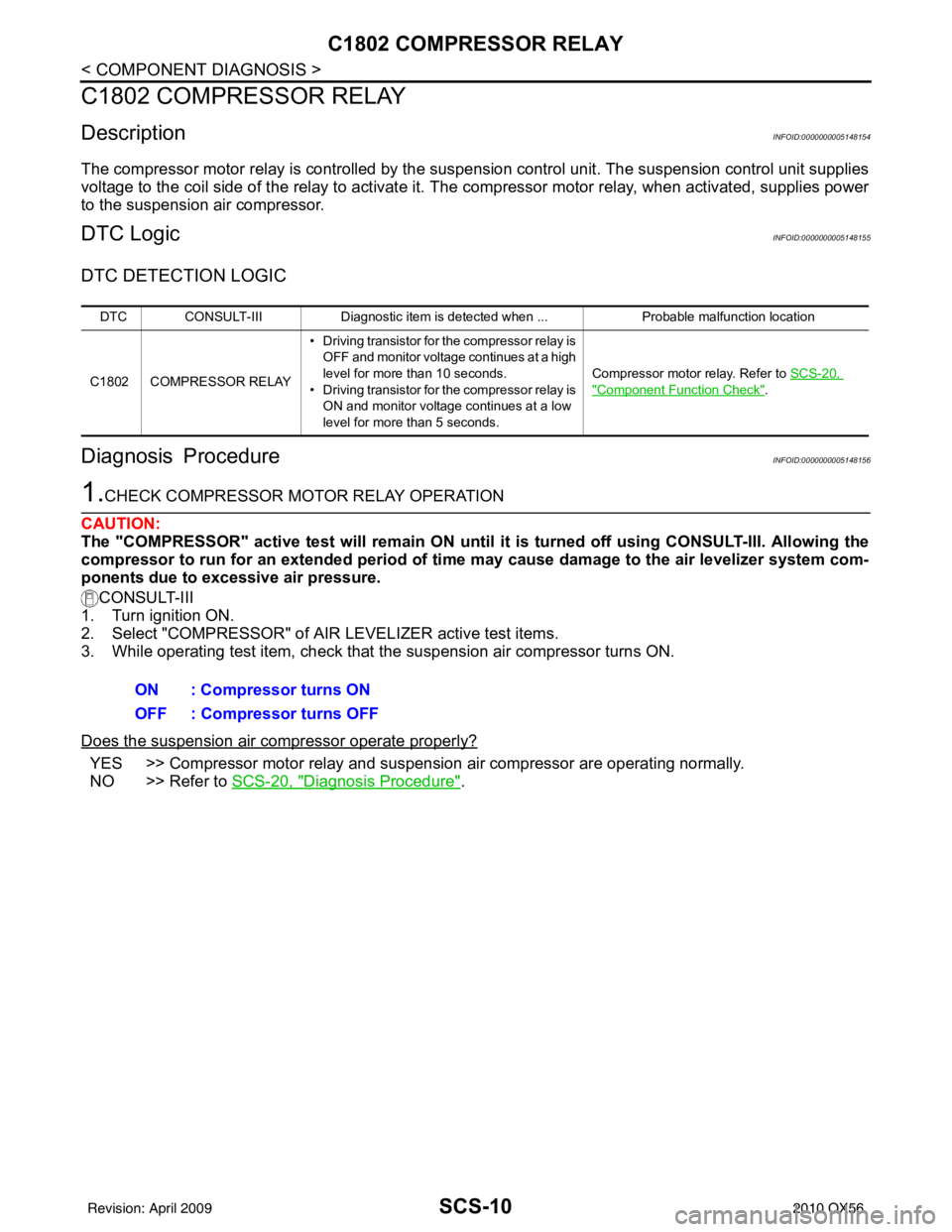
The compressor motor relay is controlled by the suspension control unit. The suspension control unit supplies
voltage to the coil side of the relay to activate it. T he compressor motor relay, when activated, supplies power
to the suspension air compressor.
DTC LogicINFOID:0000000005148155
DTC DETECTION LOGIC
Diagnosis ProcedureINFOID:0000000005148156
1.CHECK COMPRESSOR MOTOR RELAY OPERATION
CAUTION:
The "COMPRESSOR" active test will remain ON until it is turned off using CONSULT-III. Allowing the
compressor to run for an extended period of time may cause damage to the air levelizer system com-
ponents due to excessive air pressure.
CONSULT-III
1. Turn ignition ON.
2. Select "COMPRESSOR" of AIR LEVELIZER active test items.
3. While operating test item, check that the suspension air compressor turns ON.
Does the suspension air compressor operate properly?
YES >> Compressor motor relay and suspension air compressor are operating normally.
NO >> Refer to SCS-20, "
Diagnosis Procedure".
DTC CONSULT-III Diagnostic item is detected when ... Probable malfunction location
C1802 COMPRESSOR RELAY • Driving transistor for the compressor
relay is
OFF and monitor voltage continues at a high
level for more than 10 seconds.
• Driving transistor for the compressor relay is
ON and monitor voltage continues at a low
level for more than 5 seconds. Compressor motor relay. Refer to
SCS-20,
"Component Function Check".
ON : Compressor turns ON
OFF : Compressor turns OFF
Revision: April 20092010 QX56
Page 3244 of 4210

SCS-12
< COMPONENT DIAGNOSIS >
C1804 HEIGHT ADJUSTING MALFUNCTION (COMPRESSOR)
C1804 HEIGHT ADJUSTING MA LFUNCTION (COMPRESSOR)
DescriptionINFOID:0000000005148160
The compressor motor relay is controlled by the sus pension control unit. The suspension control unit supplies
voltage to the coil side of the relay to activate it. T he compressor motor relay, when activated, supplies power
to the suspension air compressor.
DTC LogicINFOID:0000000005148161
DTC DETECTION LOGIC
Diagnosis ProcedureINFOID:0000000005148162
1.CHECK COMPRESSOR MOTOR RELAY OPERATION
CAUTION:
The "COMPRESSOR" active test will remain ON until it is turned off using CONSULT-III. Allowing the
compressor to run for an extended period of time may cause damage to the air levelizer system com-
ponents due to excessive air pressure.
CONSULT-III
1. Turn ignition ON.
2. Select "COMPRESSOR" of AIR LEVELIZER active test items.
3. While operating test item, check that the suspension air compressor turns ON.
Does the suspension air compressor operate properly?
YES >> Compressor motor relay and suspension air compressor are operating normally.
NO >> Refer to SCS-20, "
Diagnosis Procedure".
DTC CONSULT-III Diagnostic item is detected when ... Probable malfunction location
C1804 VEHICLE HEIGHT AD-
JUSTING MALFUNC-
TION (COMPRESSOR) Continuous compressor relay ON time is more
than 120 seconds.
Compressor motor relay. Refer to
SCS-20,
"Component Function Check".
ON : Compressor turns ON
OFF : Compressor turns OFF
Revision: April 20092010 QX56
Page 3248 of 4210
SCS-16
< COMPONENT DIAGNOSIS >
C1808 INTEGRAL TIME MALFUNCTION SUPPLYING AIR
C1808 INTEGRAL TIME MALFUNCTION SUPPLYING AIR
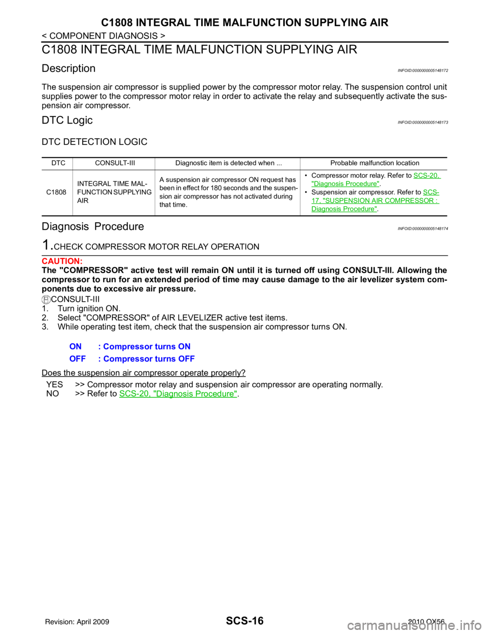
DescriptionINFOID:0000000005148172
The suspension air compressor is supplied power by the compressor motor relay. The suspension control unit
supplies power to the compressor motor relay in order to activate the relay and subsequently activate the sus-
pension air compressor.
DTC LogicINFOID:0000000005148173
DTC DETECTION LOGIC
Diagnosis ProcedureINFOID:0000000005148174
1.CHECK COMPRESSOR MOTOR RELAY OPERATION
CAUTION:
The "COMPRESSOR" active test will remain ON until it is turned off using CONSULT-III. Allowing the
compressor to run for an extended period of time may cause damage to the air levelizer system com-
ponents due to excessive air pressure.
CONSULT-III
1. Turn ignition ON.
2. Select "COMPRESSOR" of AIR LEVELIZER active test items.
3. While operating test item, check that the suspension air compressor turns ON.
Does the suspension air compressor operate properly?
YES >> Compressor motor relay and suspension air compressor are operating normally.
NO >> Refer to SCS-20, "
Diagnosis Procedure".
DTC CONSULT-III Diagnostic item is detected when ... Probable malfunction location
C1808 INTEGRAL TIME MAL-
FUNCTION SUPPLYING
AIR A suspension air compressor ON request has
been in effect for 180 seconds and the suspen-
sion air compressor has not activated during
that time. • Compressor motor relay. Refer to
SCS-20,
"Diagnosis Procedure".
• Suspension air compressor. Refer to SCS-
17, "SUSPENSION AIR COMPRESSOR :
Diagnosis Procedure".
ON : Compressor turns ON
OFF : Compressor turns OFF
Revision: April 20092010 QX56
Page 3250 of 4210
SCS-18
< COMPONENT DIAGNOSIS >
POWER SUPPLY AND GROUND CIRCUIT
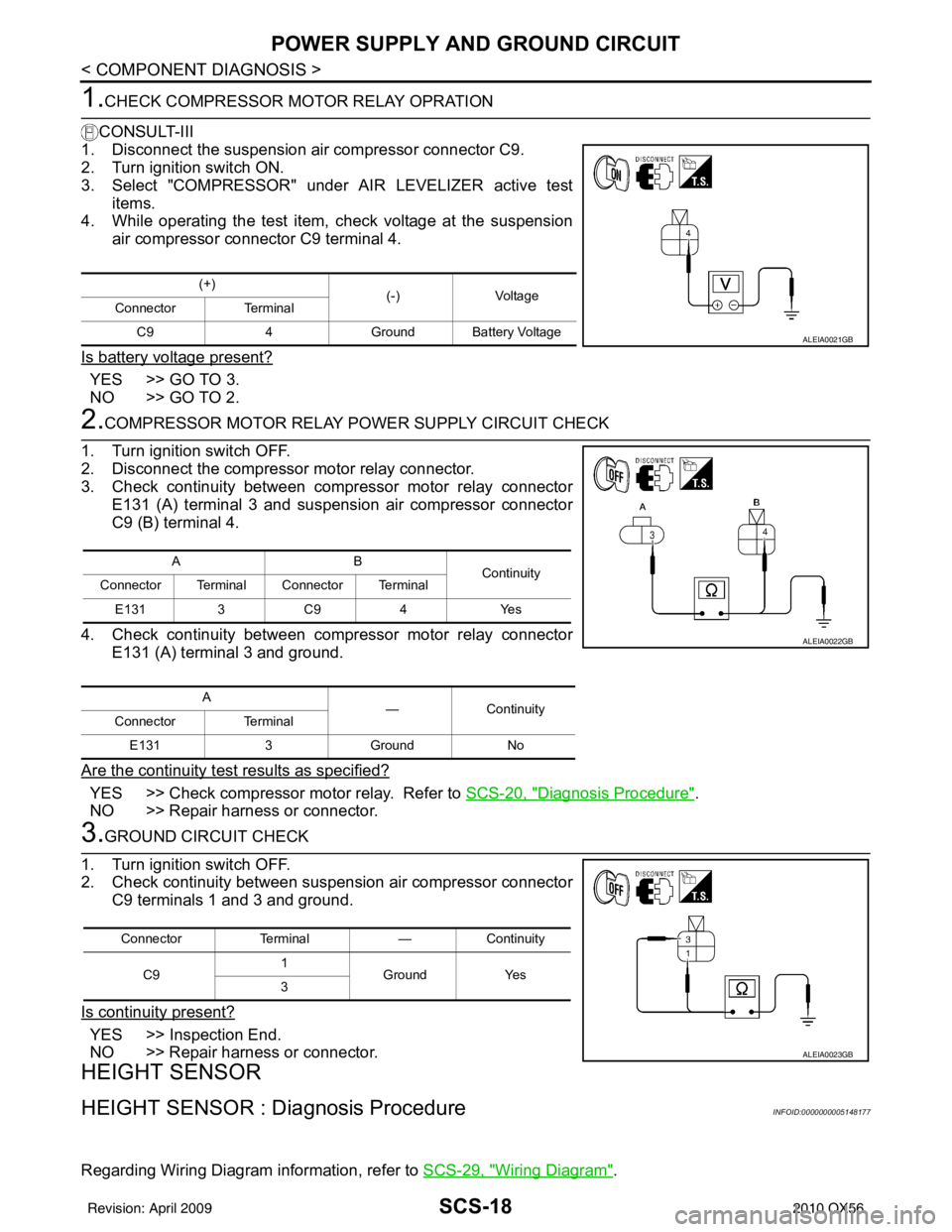
1.CHECK COMPRESSOR MOTOR RELAY OPRATION
CONSULT-III
1. Disconnect the suspension air compressor connector C9.
2. Turn ignition switch ON.
3. Select "COMPRESSOR" under AIR LEVELIZER active test items.
4. While operating the test item, check voltage at the suspension
air compressor connector C9 terminal 4.
Is battery voltage present?
YES >> GO TO 3.
NO >> GO TO 2.
2.COMPRESSOR MOTOR RELAY POWER SUPPLY CIRCUIT CHECK
1. Turn ignition switch OFF.
2. Disconnect the compressor motor relay connector.
3. Check continuity between compressor motor relay connector E131 (A) terminal 3 and suspension air compressor connector
C9 (B) terminal 4.
4. Check continuity between compressor motor relay connector E131 (A) terminal 3 and ground.
Are the continuity test results as specified?
YES >> Check compressor motor relay. Refer to SCS-20, "Diagnosis Procedure".
NO >> Repair harness or connector.
3.GROUND CIRCUIT CHECK
1. Turn ignition switch OFF.
2. Check continuity between suspension air compressor connector C9 terminals 1 and 3 and ground.
Is continuity present?
YES >> Inspection End.
NO >> Repair harness or connector.
HEIGHT SENSOR
HEIGHT SENSOR : Dia gnosis ProcedureINFOID:0000000005148177
Regarding Wiring Diagram information, refer to SCS-29, "Wiring Diagram".
(+)
(-)Voltage
Connector Terminal
C9 4Ground Battery Voltage
ALEIA0021GB
AB
Continuity
Connector Terminal Connector Terminal
E131 3 C9 4 Yes
A —Continuity
Connector Terminal
E131 3Ground No
ALEIA0022GB
Connector Terminal —Continuity
C9 1
Ground Yes
3
ALEIA0023GB
Revision: April 20092010 QX56