2010 INFINITI QX56 relay
[x] Cancel search: relayPage 3484 of 4210

SN-12
< FUNCTION DIAGNOSIS >
FRONT AND REAR SONAR SYSTEM
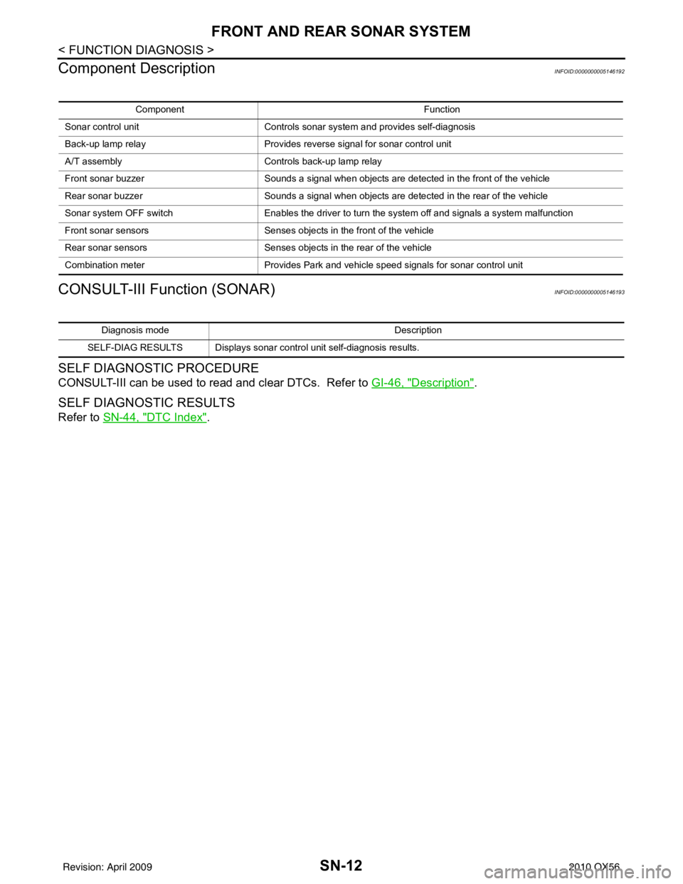
Component Description
INFOID:0000000005146192
CONSULT-III Function (SONAR)INFOID:0000000005146193
SELF DIAGNOSTIC PROCEDURE
CONSULT-III can be used to read and clear DTCs. Refer to GI-46, "Description".
SELF DIAGNOSTIC RESULTS
Refer to SN-44, "DTC Index".
Component Function
Sonar control unit Controls sonar system and provides self-diagnosis
Back-up lamp relay Provides reverse signal for sonar control unit
A/T assembly Controls back-up lamp relay
Front sonar buzzer Sounds a signal when objects are detected in the front of the vehicle
Rear sonar buzzer Sounds a signal when objects are detected in the rear of the vehicle
Sonar system OFF switch Enables the driver to turn the system off and signals a system malfunction
Front sonar sensors Senses objects in the front of the vehicle
Rear sonar sensors Senses objects in the rear of the vehicle
Combination meter Provides Park and vehicle speed signals for sonar control unit
Diagnosis mode Description
SELF-DIAG RESULTS Displays sonar control unit self-diagnosis results.
Revision: April 20092010 QX56
Page 3517 of 4210

SN
SONAR SYSTEM SYMPTOMSSN-45
< SYMPTOM DIAGNOSIS >
C
DE
F
G H
I
J
K L
M B A
O P
SYMPTOM DIAGNOSIS
SONAR SYSTEM SYMPTOMS
Symptom TableINFOID:0000000005146213
Symptom Repair order
When the sonar system is OFF, the OFF indicator does not light
and the sonar buzzer does not sound. 1. Check sonar system OFF switch. Refer to
SN-20, "
Compo-
nent Inspection" or SN-19, "Diagnosis Procedure (With
Front and Rear Sonar System)".
2. Check harness and connections for sonar system OFF
switch.
3. Replace sonar control unit. Refer to SN-50, "
Removal and
Installation".
When the sonar system is OFF, the OFF indicator lamp does not
light but the sonar buzzer does sound. 1. Check sonar system OFF switch. Refer to
SN-19, "
Diagno-
sis Procedure (With Rear Sonar System)" or SN-19, "Diag-
nosis Procedure (With Front and Rear Sonar System)".
2. Check harness and connections for sonar system OFF indi- cator lamp.
3. Replace sonar control unit.
When the sonar system is OFF, the sonar buzzer does not sound
but the OFF indicator lamp lights. 1. Check sonar buzzer. Refer to
SN-18, "
Component Inspec-
tion" or SN-17, "Diagnosis Procedure (With Front and Rear
Sonar System)".
2. Check harness and connections between sonar buzzer and sonar control unit.
3. Replace sonar control unit.
When sonar system is ON, the sonar system OFF indicator lamp
lights up and the sonar buzzer sounds intermittently (for about 4
seconds). (Rear sonar system only) 1. Check harnesses between sonar sensors and sonar control
unit for an open condition.
2. Check sonar sensors. Refer to SN-5, "
Preliminary Check".
3. Replace sonar control unit.
The sonar system still operates when the sonar system is OFF. 1. Replace sonar control unit.
When the transmission gear selector lever is in the R position and
the sonar system is ON, the rear sonar system does not operate. 1. Check transmissin range switch. Refer to
TM-45, "
Diagnosis
Procedure".
2. Check back-up lamp relay.
3. Check related harness and connections for back-up lamp re- lay.
4. Replace sonar control unit.
When the transmission gear selector lever is in a forward drive
gear and the sonar system is ON, the front sonar system does not
operate. (With front and rear sonar system only) 1. Check harness and connections between sonar control unit
and combination meter.
2. Replace sonar control unit.
Sonar system OFF indicator lamp lights up and buzzer sounds al-
though there are no obstacles within the detection range. 1. Check sonar sensors.
2. Check harness and connections between sonar sensors
and sonar control unit.
3. Replace sonar control unit.
The sonar sensors do not detect objects in the detectable range. 1. Check sonar sensors.
2. Replace sonar control unit.
Revision: April 20092010 QX56
Page 3645 of 4210

HEATED STEERING WHEELST-7
< FUNCTION DIAGNOSIS >
C
DE
F
H I
J
K L
M A
B
ST
N
O P
FUNCTION DIAGNOSIS
HEATED STEERING WHEEL
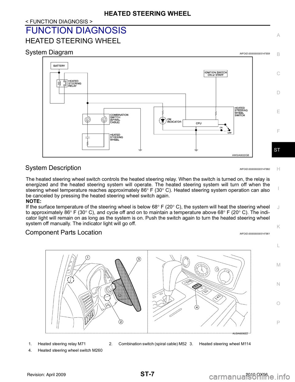
System DiagramINFOID:0000000005147859
System DescriptionINFOID:0000000005147860
The heated steering wheel switch controls the heated steeri ng relay. When the switch is turned on, the relay is
energized and the heated steering system will operate. T he heated steering system will turn off when the
steering wheel temperature reaches approximately 86 ° F (30 ° C). Heated steering system operation can also
be canceled by pressing the heated steering wheel switch again.
NOTE:
If the surface temperature of the steering wheel is below 68 ° F (20 ° C), the system will heat the steering wheel
to approximately 86 ° F (30 ° C), and cycle off and on to maintain a temperature above 68 ° F (20 ° C). The indi-
cator light will remain on as long as the system is on. Push the switch again to turn the heated steering wheel
system off manually. The indicator light will go off.
Component Parts LocationINFOID:0000000005147861
AWGIA0022GB
1. Heated steering relay M71 2. Combination switch (spiral cable) M52 3. Heated steering wheel M114
4. Heated steering wheel switch M260
ALGIA0030ZZ
Revision: April 20092010 QX56
Page 3646 of 4210

ST-8
< FUNCTION DIAGNOSIS >
HEATED STEERING WHEEL
Component Description
INFOID:0000000005147862
Heated steering wheel switch • Controls the heated steering relay and operates the heated steering system.
• Turns the indicator lamp ON when the system is activated.
Heated steering relay • Operates the heated steering system with the control signal from the heated steering
wheel switch.
Heated steering wheel • Heats the heating element with the power supplied from the heated steering relay.
Revision: April 20092010 QX56
Page 3684 of 4210

STARTING SYSTEMSTR-9
< FUNCTION DIAGNOSIS >
C
DE
F
G H
I
J
K L
M A
STR
NP
O
Component DescriptionINFOID:0000000005149553
Component part
Description
TCM TCM supplies power to the starter relay inside the IPDM E/R when
the selector lever is shifted to the P or N position.
BCM BCM sends a starter request signal to the CPU of the IPDM E/R
over the CAN communication lines.
IPDM E/R CPU inside IPDM E/R operates the starter relay at the request of
the BCM over the CAN communication lines.
Starter motor The starter motor plunger closes and the motor is supplied with
battery power, which in turn cranks the engine, when the “S” ter-
minal is supplied with electric power.
Revision: April 20092010 QX56
Page 3696 of 4210

TM-1
TRANSMISSION & DRIVELINE
CEF
G H
I
J
K L
M
SECTION TM
A
B
TM
N
O P
CONTENTS
TRANSAXLE & TRANSMISSION
BASIC INSPECTION ....... .............................5
DIAGNOSIS AND REPAIR WORKFLOW ..... .....5
Work Flow ........................................................... ......5
Diagnostic Work Sheet ..............................................6
FUNCTION DIAGNOSIS ...............................8
A/T CONTROL SYSTEM ................................ .....8
Cross-Sectional View (2WD models) .................. ......8
Cross-Sectional View (4WD models) ........................9
Shift Mechanism ........................................................9
TCM Function ..........................................................20
CAN Communication ...............................................21
Input/Output Signal of TCM .....................................22
Line Pressure Control .............................................22
Shift Control ........................................................ ....24
Lock-up Control .......................................................25
Engine Brake Control ..............................................26
Control Valve ...........................................................26
Component Parts Location ......................................28
A/T SHIFT LOCK SYSTEM ............................ ....29
System Description ............................................. ....29
Component Parts Location ......................................29
ON BOARD DIAGNOSTIC (OBD) SYSTEM ......30
Introduction ......................................................... ....30
OBD-II Function for A/T System ..............................30
One or Two Trip Detection Logic of OBD-II ............30
OBD-II Diagnostic Trouble Code (DTC) ..................30
Malfunction Indicator Lamp (MIL) ............................31
DIAGNOSIS SYSTEM (TCM) .............................32
CONSULT-III Function (TRANSMISSION) ......... ....32
Diagnosis Procedure without CONSULT-III ........ ....37
COMPONENT DIAGNOSIS .........................40
U1000 CAN COMM CI RCUIT .............................40
Description .......................................................... ....40
On Board Diagnosis Logic ......................................40
Possible Cause .................................................... ....40
DTC Confirmation Procedure ..................................40
Diagnosis Procedure ...............................................40
P0615 STARTER RELAY .................................41
Description ...............................................................41
CONSULT-III Reference Value in Data Monitor
Mode .................................................................... ....
41
On Board Diagnosis Logic .......................................41
Possible Cause ........................................................41
DTC Confirmation Procedure ..................................41
Diagnosis Procedure ...............................................41
P0700 TRANSMISSION CONTROL .................44
Description ...............................................................44
On Board Diagnosis Logic .......................................44
Possible Cause ........................................................44
DTC Confirmation Procedure ..................................44
Diagnosis Procedure ...............................................44
P0705 TRANSMISSION RANGE SWITCH A ...45
Description ...............................................................45
CONSULT-III Reference Value in Data Monitor
Mode .................................................................... ....
45
On Board Diagnosis Logic .......................................45
Possible Cause ........................................................45
DTC Confirmation Procedure ..................................45
Diagnosis Procedure ...............................................45
P0717 INPUT SPEED SENSOR A ....................48
Description ...............................................................48
CONSULT-III Reference Value in Data Monitor
Mode .................................................................... ....
48
On Board Diagnosis Logic .......................................48
Possible Cause ........................................................48
DTC Confirmation Procedure ..................................48
Diagnosis Procedure ...............................................48
P0720 OUTPUT SPEED SENSOR ...................50
Description ...............................................................50
CONSULT-III Reference Value in Data Monitor
Mode .................................................................... ....
50
Revision: April 20092010 QX56
Page 3716 of 4210

A/T CONTROL SYSTEMTM-21
< FUNCTION DIAGNOSIS >
CEF
G H
I
J
K L
M A
B
TM
N
O P
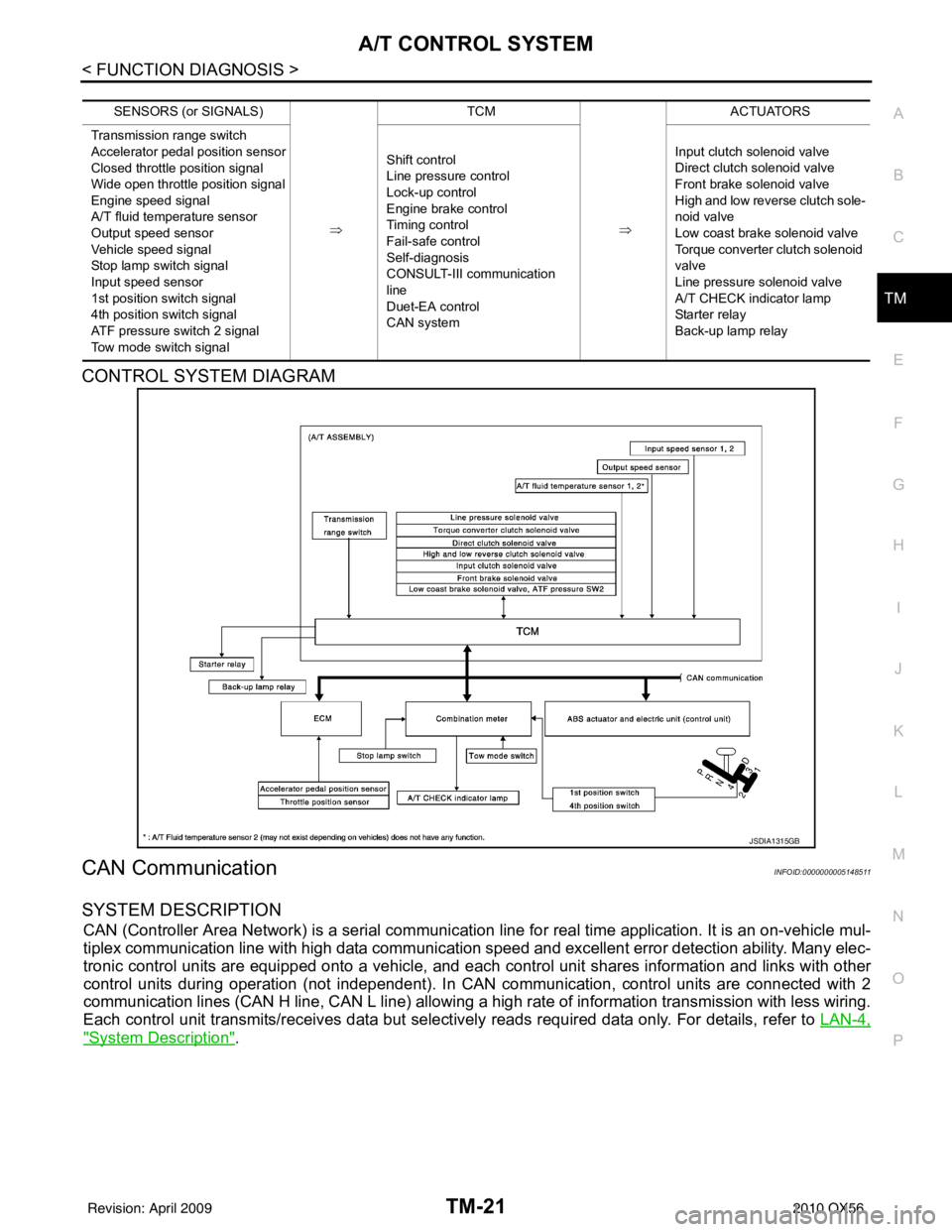
CONTROL SYSTEM DIAGRAM
CAN CommunicationINFOID:0000000005148511
SYSTEM DESCRIPTION
CAN (Controller Area Network) is a serial communication line for real time application. It is an on-vehicle mul-
tiplex communication line with high data communication speed and excellent error detection ability. Many elec-
tronic control units are equipped onto a vehicle, and each control unit shares information and links with other
control units during operation (not independent). In CAN communication, control units are connected with 2
communication lines (CAN H line, CAN L line) allowing a high rate of information transmission with less wiring.
Each control unit transmits/receives data but selectively reads required data only. For details, refer to LAN-4,
"System Description".
SENSORS (or SIGNALS)
⇒TCM
⇒ACTUATORS
Transmission range switch
Accelerator pedal position sensor
Closed throttle position signal
Wide open throttle position signal
Engine speed signal
A/T fluid temperature sensor
Output speed sensor
Vehicle speed signal
Stop lamp switch signal
Input speed sensor
1st position switch signal
4th position switch signal
ATF pressure switch 2 signal
Tow mode switch signal Shift control
Line pressure control
Lock-up control
Engine brake control
Timing control
Fail-safe control
Self-diagnosis
CONSULT-III co
mmunication
line
Duet-EA control
CAN system Input clutch solenoid valve
Direct clutch solenoid valve
Front brake solenoid valve
High and low reverse clutch sole-
noid valve
Low coast brake solenoid valve
Torque converter clutch solenoid
valve
Line pressure solenoid valve
A/T CHECK indicator lamp
Starter relay
Back-up lamp relay
JSDIA1315GB
Revision: April 20092010 QX56
Page 3717 of 4210

TM-22
< FUNCTION DIAGNOSIS >
A/T CONTROL SYSTEM
Input/Output Signal of TCM
INFOID:0000000005148512
*1: Spare for output speed sensor
*2: Spare for accelerator pedal position signal
*3: If these input and output signals are different, the TCM triggers the fail-safe function.
*4: CAN comm unications
*5: Used as a condition for starting self-diagnostics; if self-diagnostics are not started, it is judged that there is some kin d of error.
*6: A/T fluid temperature sensor 2 does not have any function.
Line Pressure ControlINFOID:0000000005148513
• When an input torque signal equivalent to the engine drive force is sent from the ECM to the TCM, the TCM
controls the line pressure solenoid.
Control item Line
pres- sure
control Vehicle
speed
control S h i f t
control Lock-up
control Engine
brake
control Fail-safe
function (*3) Self-diag-
nostics
function
Input Accelerator pedal position signal
(*4)XXXXX X X
Output speed sensor X X X X X X
Vehicle speed signal
(*1) (*4)XXXX X
Closed throttle position signal
(*4)(*2) X (*2) X X (*2) X(*5) X
Wide open throttle position signal
(*4)(*2) X (*2) X (*2) X(*5) X
Input speed sensor 1 X XXX X
Input speed sensor 2
(for 4th speed only) XX X
X X
Engine speed signals
(*4)XX
Transmission range switch X X X X X X X
Stop lamp switch signal
(*4)XXX (*5) X
A/T fluid temperature sensors 1, 2 (*6) X X X X X X X
ASCD Operation signal
(*4)XXXX
Overdrive cancel sig-
nal
(*4)XXX
TCM power supply voltage signal X X X X X X
Output Direct clutch solenoid
X XX X
Input clutch solenoid X XX X
High and low reverse clutch solenoid X XX X
Front brake solenoid X XX X
Low coast brake solenoid (ATF pressure
switch 2) XX X X X
Line pressure solenoid X X X X X X X
TCC solenoid XX X
Starter relay XX
Revision: April 20092010 QX56