2010 INFINITI QX56 relay
[x] Cancel search: relayPage 3814 of 4210
TCM
TM-119
< ECU DIAGNOSIS >
C EF
G H
I
J
K L
M A
B
TM
N
O P
High and Low Revers
e Clutch Solenoid
• If a (electrical or functional) malfunction occurs with the solenoid either “ON” or “OFF”, the transmission is
held in 4GR to make driving possible.
Input Speed Sensor 1 or 2
• The control is the same as if there were no input speed sensors, 5GR is prohibited.
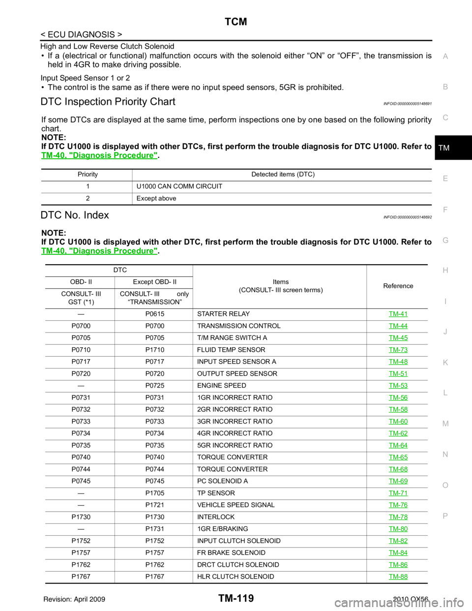
DTC Inspection Priority ChartINFOID:0000000005148691
If some DTCs are displayed at the same time, perform inspections one by one based on the following priority
chart.
NOTE:
If DTC U1000 is displayed with other DTCs, first pe rform the trouble diagnosis for DTC U1000. Refer to
TM-40, "
Diagnosis Procedure".
DTC No. IndexINFOID:0000000005148692
NOTE:
If DTC U1000 is displayed with other DTC, first pe rform the trouble diagnosis for DTC U1000. Refer to
TM-40, "
Diagnosis Procedure".
Priority Detected items (DTC)
1 U1000 CAN COMM CIRCUIT
2 Except above
DTC
Items
(CONSULT- III screen terms) Reference
OBD- II
Except OBD- II
CONSULT- III GST (*1) CONSULT- III only
“TRANSMISSION”
— P0615STARTER RELAY TM-41
P0700P0700TRANSMISSION CONTROL TM-44
P0705P0705T/M RANGE SWITCH A TM-45
P0710P1710FLUID TEMP SENSOR TM-73
P0717P0717INPUT SPEED SENSOR A TM-48
P0720P0720OUTPUT SPEED SENSOR TM-51
—P0725ENGINE SPEED TM-53
P0731P07311GR INCORRECT RATIO TM-56
P0732P07322GR INCORRECT RATIO TM-58
P0733P07333GR INCORRECT RATIO TM-60
P0734P07344GR INCORRECT RATIO TM-62
P0735P07355GR INCORRECT RATIO TM-64
P0740P0740TORQUE CONVERTER TM-65
P0744 P0744 TORQUE CONVERTER TM-68
P0745P0745PC SOLENOID A TM-69
—P1705TP SENSOR TM-71
—P1721VEHICLE SPEED SIGNAL TM-76
P1730P1730INTERLOCK TM-78
—P17311GR E/BRAKING TM-80
P1752P1752INPUT CLUTCH SOLENOID TM-82
P1757P1757FR BRAKE SOLENOID TM-84
P1762P1762DRCT CLUTCH SOLENOID TM-86
P1767P1767HLR CLUTCH SOLENOID TM-88
Revision: April 20092010 QX56
Page 3815 of 4210
TM-120
< ECU DIAGNOSIS >
TCM
*1: These numbers are prescribed by SAE J2012.
*2: These malfunctions cannot be displayed MIL if another malfunction is assigned to MIL.
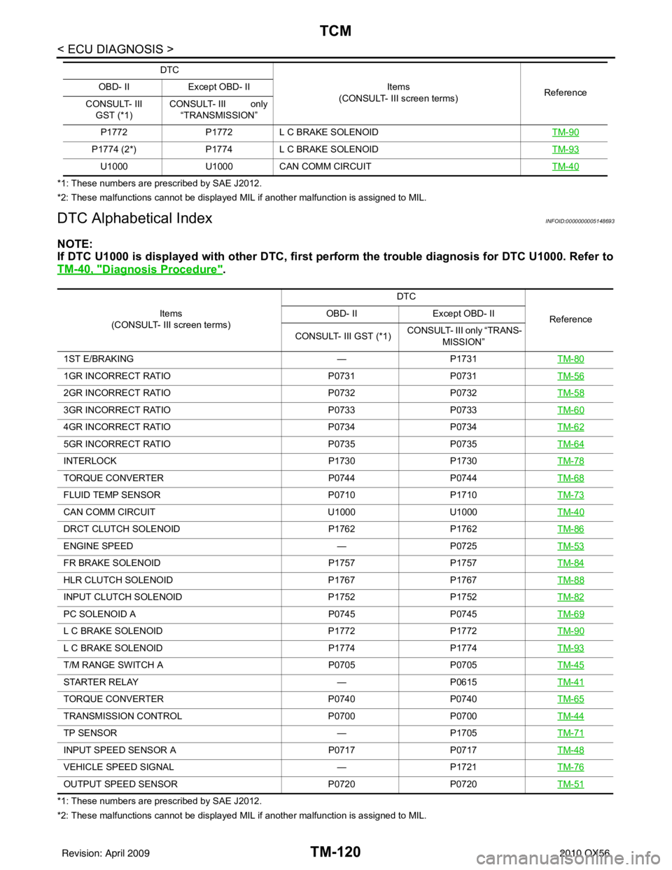
DTC Alphabetical IndexINFOID:0000000005148693
NOTE:
If DTC U1000 is displayed with other DTC, first perform the trouble diagnosis for DTC U1000. Refer to
TM-40, "
Diagnosis Procedure".
*1: These numbers are prescribed by SAE J2012.
*2: These malfunctions cannot be displayed MIL if another malfunction is assigned to MIL. P1772
P1772L C BRAKE SOLENOID TM-90
P1774 (2*) P1774 L C BRAKE SOLENOID TM-93
U1000U1000CAN COMM CIRCUIT TM-40
DTC
Items
(CONSULT- III screen terms) Reference
OBD- II
Except OBD- II
CONSULT- III GST (*1) CONSULT- III only
“TRANSMISSION”
Items
(CONSULT- III screen terms) DTC
Reference
OBD- II
Except OBD- II
CONSULT- III GST (*1) CONSULT- III only “TRANS-
MISSION”
1ST E/BRAKING —P1731TM-80
1GR INCORRECT RATIO P0731P0731TM-56
2GR INCORRECT RATIO P0732P0732TM-58
3GR INCORRECT RATIO P0733P0733TM-60
4GR INCORRECT RATIO P0734P0734TM-62
5GR INCORRECT RATIO P0735P0735TM-64
INTERLOCK P1730P1730TM-78
TORQUE CONVERTER P0744 P0744 TM-68
FLUID TEMP SENSOR P0710P1710TM-73
CAN COMM CIRCUIT U1000U1000TM-40
DRCT CLUTCH SOLENOID P1762P1762 TM-86
ENGINE SPEED —P0725TM-53
FR BRAKE SOLENOID P1757P1757TM-84
HLR CLUTCH SOLENOID P1767P1767TM-88
INPUT CLUTCH SOLENOID P1752P1752TM-82
PC SOLENOID A P0745P0745TM-69
L C BRAKE SOLENOID P1772P1772TM-90
L C BRAKE SOLENOID P1774 P1774 TM-93
T/M RANGE SWITCH A P0705P0705TM-45
STARTER RELAY —P0615TM-41
TORQUE CONVERTER P0740P0740TM-65
TRANSMISSION CONTROL P0700P0700TM-44
TP SENSOR —P1705TM-71
INPUT SPEED SENSOR A P0717P0717TM-48
VEHICLE SPEED SIGNAL —P1721TM-76
OUTPUT SPEED SENSOR P0720P0720TM-51
Revision: April 20092010 QX56
Page 4020 of 4210
WCS
KEY SWITCH SIGNAL CIRCUITWCS-21
< COMPONENT DIAGNOSIS >
C
DE
F
G H
I
J
K L
M B A
O P
KEY SWITCH SIGNAL CIRCUIT
DescriptionINFOID:0000000005146162
Transmits a key switch signal to the BCM.
Component Function CheckINFOID:0000000005146163
1.CHECK BCM INPUT SIGNAL
Select “DATA MONITOR” for “BCM” and c heck the “KEY ON SW” monitor value.
>> Inspection End.
Diagnosis ProcedureINFOID:0000000005146164
Regarding Wiring Diagram information, refer to WCS-23, "Wiring Diagram".
1.CHECK FUSE
Check if the key switch and ignition knob switch 10A fuse (No. 62, located in the fuse and relay box) is blown.
Is the fuse blown?
YES >> Be sure to repair the cause of malfunction before installing new fuse.
NO >> GO TO 2
2.CHECK BCM INPUT SIGNAL
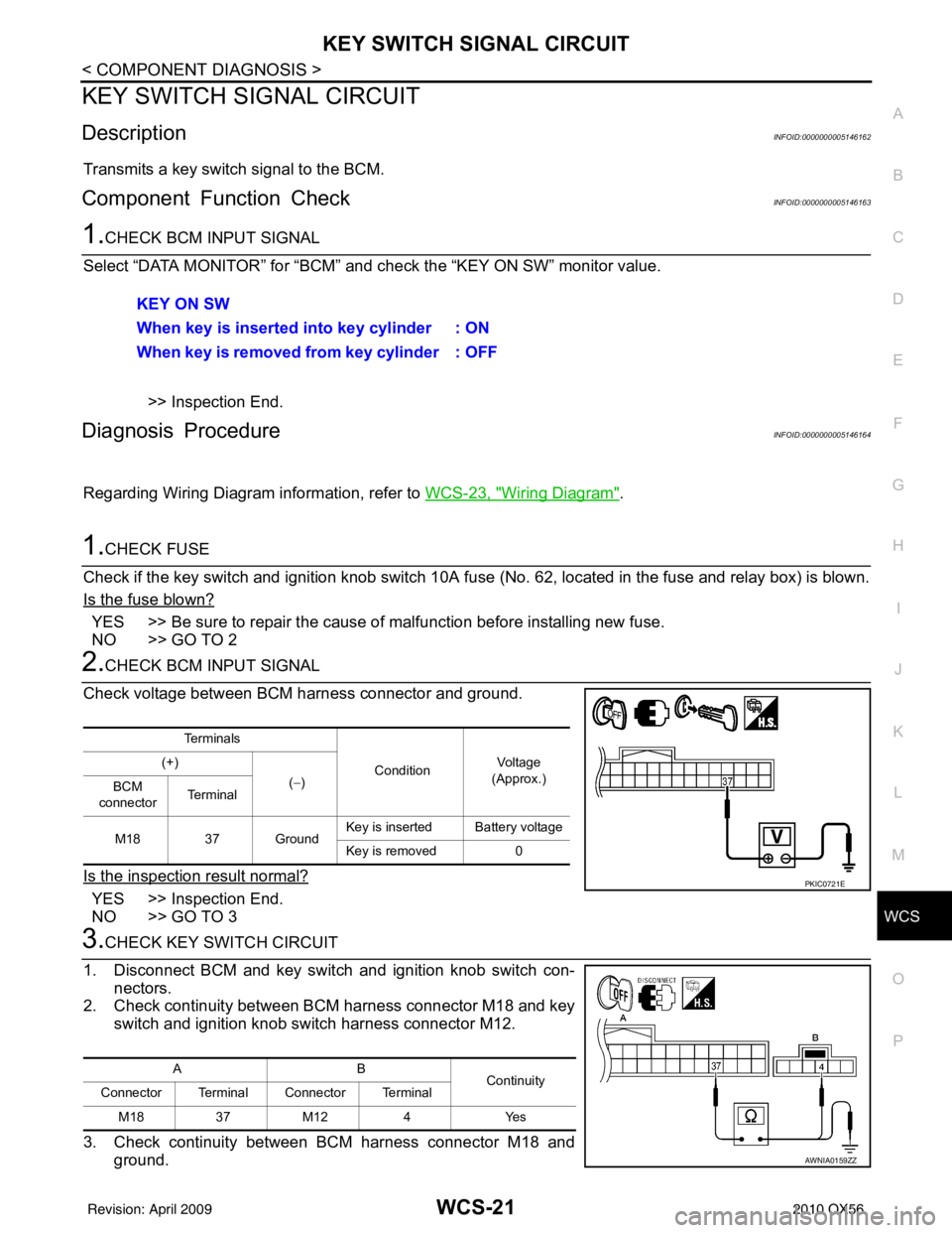
Check voltage between BCM harness connector and ground.
Is the inspection result normal?
YES >> Inspection End.
NO >> GO TO 3
3.CHECK KEY SWITCH CIRCUIT
1. Disconnect BCM and key switch and ignition knob switch con- nectors.
2. Check continuity between BCM harness connector M18 and key
switch and ignition knob switch harness connector M12.
3. Check continuity between BCM harness connector M18 and ground.KEY ON SW
When key is inserted into key cylinder : ON
When key is removed from key cylinder : OFF
Te r m i n a l s
ConditionVo l ta g e
(Approx.)
(+)
(−)
BCM
connector Te r m i n a l
M18 37 Ground Key is inserted Battery voltage
Key is removed 0
PKIC0721E
AB
Continuity
Connector Terminal Connector Terminal
M18 37M12 4 Yes
AWNIA0159ZZ
Revision: April 20092010 QX56
Page 4125 of 4210
WW-4
< FUNCTION DIAGNOSIS >
FRONT WIPER AND WASHER SYSTEM
FUNCTION DIAGNOSIS
FRONT WIPER AND WASHER SYSTEM
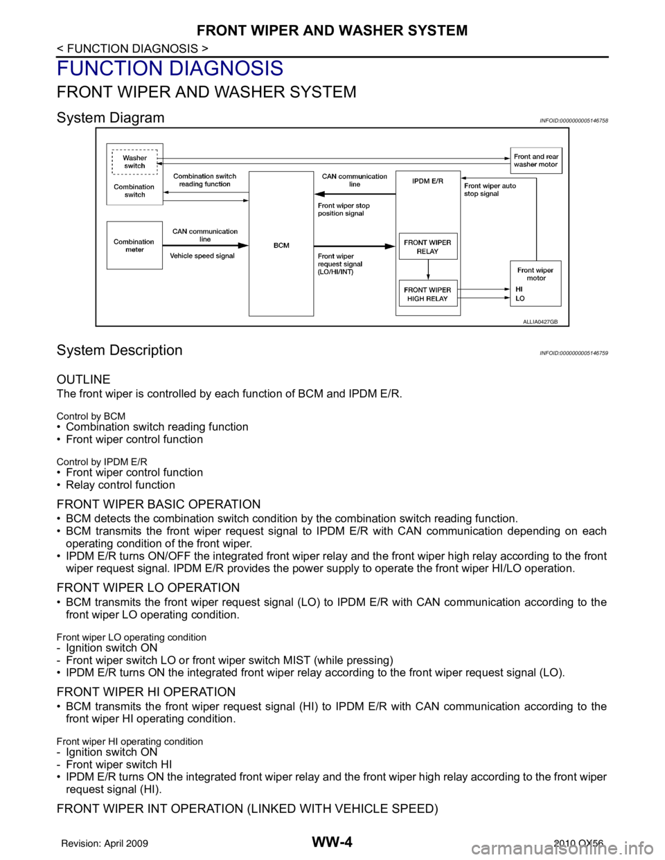
System DiagramINFOID:0000000005146758
System DescriptionINFOID:0000000005146759
OUTLINE
The front wiper is controlled by each function of BCM and IPDM E/R.
Control by BCM
• Combination switch reading function
• Front wiper control function
Control by IPDM E/R
• Front wiper control function
• Relay control function
FRONT WIPER BASIC OPERATION
• BCM detects the combination switch conditi on by the combination switch reading function.
• BCM transmits the front wiper request signal to IPDM E/R with CAN communication depending on each
operating condition of the front wiper.
• IPDM E/R turns ON/OFF the integrated front wiper rela y and the front wiper high relay according to the front
wiper request signal. IPDM E/R provides the power supply to operate the front wiper HI/LO operation.
FRONT WIPER LO OPERATION
• BCM transmits the front wiper request signal (LO) to IPDM E/R with CAN communication according to the
front wiper LO operating condition.
Front wiper LO operating condition
- Ignition switch ON
- Front wiper switch LO or front wiper switch MIST (while pressing)
• IPDM E/R turns ON the integrated front wiper rela y according to the front wiper request signal (LO).
FRONT WIPER HI OPERATION
• BCM transmits the front wiper request signal (HI) to IPDM E/R with CAN communication according to the
front wiper HI operating condition.
Front wiper HI operating condition
- Ignition switch ON
- Front wiper switch HI
• IPDM E/R turns ON the integrated front wiper relay and the front wiper high relay according to the front wiper request signal (HI).
FRONT WIPER INT OPERATION (L INKED WITH VEHICLE SPEED)
ALLIA0427GB
Revision: April 20092010 QX56
Page 4126 of 4210
FRONT WIPER AND WASHER SYSTEMWW-5
< FUNCTION DIAGNOSIS >
C
DE
F
G H
I
J
K
M A
B
WW
N
O P
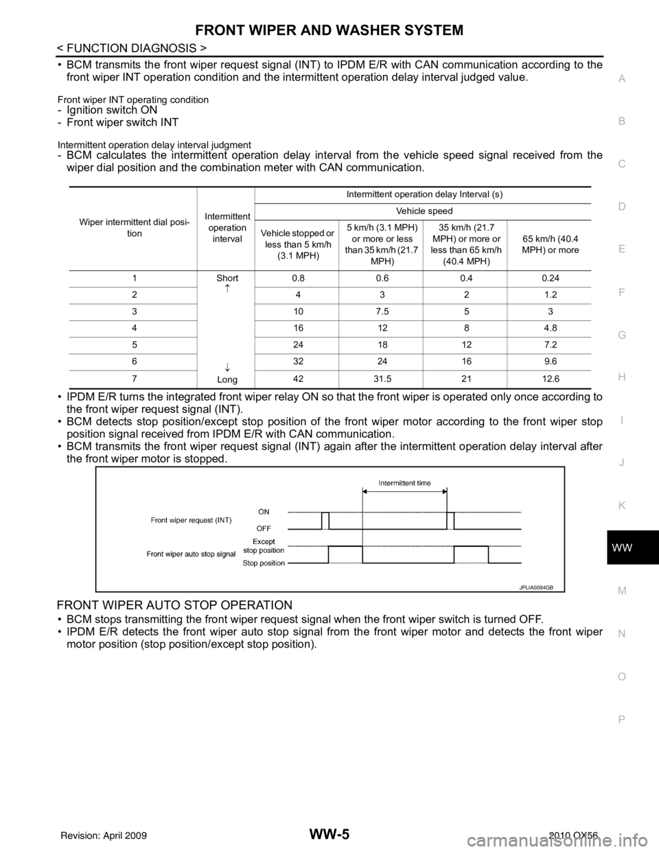
• BCM transmits the front wiper request signal (INT) to IPDM E/R with CAN communication according to the
front wiper INT operation condition and the intermittent operation delay interval judged value.
Front wiper INT operating condition- Ignition switch ON
- Front wiper switch INT
Intermittent operation delay interval judgment- BCM calculates the intermittent operation delay inte rval from the vehicle speed signal received from the
wiper dial position and the combination meter with CAN communication.
• IPDM E/R turns the integrated front wiper relay ON so that the front wiper is operated only once according to the front wiper request signal (INT).
• BCM detects stop position/except st op position of the front wiper motor according to the front wiper stop
position signal received from IP DM E/R with CAN communication.
• BCM transmits the front wiper request signal (INT) again after the intermittent operation delay interval after the front wiper motor is stopped.
FRONT WIPER AUTO STOP OPERATION
• BCM stops transmitting the front wiper request si gnal when the front wiper switch is turned OFF.
• IPDM E/R detects the front wiper auto stop signal fr om the front wiper motor and detects the front wiper
motor position (stop positi on/except stop position).
Wiper intermittent dial posi-
tion Intermittent
operation interval Intermittent operation delay Interval (s)
Vehicle speed
Vehicle stopped or less than 5 km/h (3.1 MPH) 5 km/h (3.1 MPH)
or more or less
than 35 km/h (21.7 MPH) 35 km/h (21.7
MPH) or more or
less than 65 km/h (40.4 MPH) 65 km/h (40.4
MPH) or more
1S hort
↑
↓
Long 0.8
0.60.40.24
2 4321 .2
31 07.5 5 3
41 612 84.8
5 241 8127.2
6 322 4169.6
7 423 1.52 11 2.6
JPLIA0094GB
Revision: April 20092010 QX56
Page 4127 of 4210

WW-6
< FUNCTION DIAGNOSIS >
FRONT WIPER AND WASHER SYSTEM
• When the front wiper request signal is stopped, IPDM E/R turns ON the front wiper relay until the front wiper
motor returns to the stop position.
NOTE:
• BCM stops the transmitting of the front wiper request signal when the ignition switch is OFF.
• IPDM E/R turns the front wiper relay OFF when the ignition switch is OFF.
FRONT WIPER OPERATION LINKED WITH WASHER
• BCM transmits the front wiper request signal (LO) to IPDM E/R with CAN communication according to the
washer linked operating condition of the front wiper.
• BCM transmits the front wiper request signal (LO) so that the front wiper operates approximately 3 times when the front washer s witch OFF is detected.
Washer linked operating condition of front wiper
- Ignition switch ON
- Front washer switch ON (0.4 second or more)
• IPDM E/R turns ON the integrated front wiper rela y according to the front wiper request signal (LO).
• The front and rear washer motor is grounded through the combination switch with the front washer switch
ON.
FRONT WIPER DROP WIPE OPERATION
• BCM controls the front wiper to operate once accordi ng to the conditions of front wiper drop wipe operation.
Front wiper drop wipe operating condition- Ignition switch ON
- Front wiper switch OFF
- Front washer switch OFF
• BCM transmits the front wiper request signal (LO) to IPDM E/R with CAN communication so that the front
wiper operate once three seconds after front wiper operation linked with washer.
• IPDM E/R turns ON the integrated front wiper rela y according to the front wiper request signal (LO).
FRONT WIPER FAIL−SAFE OPERATION
• IPDM E/R performs the fail-safe function when the front wiper auto stop circuit is malfunctioning. Refer to
WW-68, "
FailSafe".
JPLIA0095GB
Revision: April 20092010 QX56
Page 4128 of 4210
FRONT WIPER AND WASHER SYSTEMWW-7
< FUNCTION DIAGNOSIS >
C
DE
F
G H
I
J
K
M A
B
WW
N
O P
Component Parts LocationINFOID:0000000005146760
Component DescriptionINFOID:0000000005146761
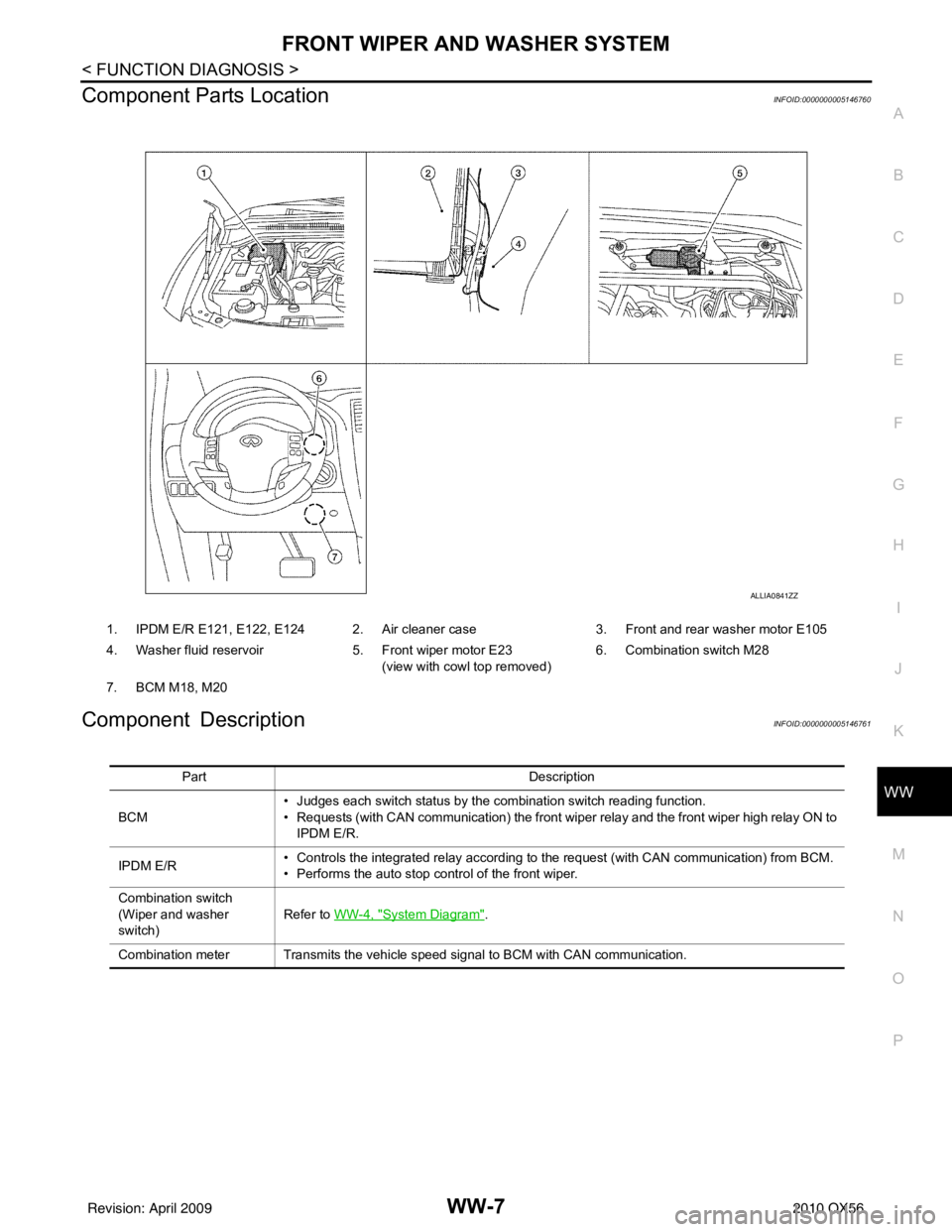
1. IPDM E/R E121, E122, E124 2. Air cleaner case 3. Front and rear washer motor E105
4. Washer fluid reservoir 5. Front wiper motor E23
(view with cowl top removed) 6. Combination switch M28
7. BCM M18, M20
ALLIA0841ZZ
Part Description
BCM • Judges each switch status by the combination switch reading function.
• Requests (with CAN communication) the front wiper relay and the front wiper high relay ON to
IPDM E/R.
IPDM E/R • Controls the integrated relay according to the request (with CAN communication) from BCM.
• Performs the auto stop control of the front wiper.
Combination switch
(Wiper and washer
switch) Refer to WW-4, "
System Diagram".
Combination meter Transmits the vehicle speed signal to BCM with CAN communication.
Revision: April 20092010 QX56
Page 4136 of 4210
DIAGNOSIS SYSTEM (IPDM E/R)WW-15
< FUNCTION DIAGNOSIS >
C
DE
F
G H
I
J
K
M A
B
WW
N
O P
CONSULT - III Function (IPDM E/R)INFOID:0000000005369214
APPLICATION ITEM
CONSULT-III performs the following functions via CAN communication with IPDM E/R.
SELF DIAGNOSTIC
Refer to PCS-32, "DTCIndex".
DATA MONITOR
Monitor item
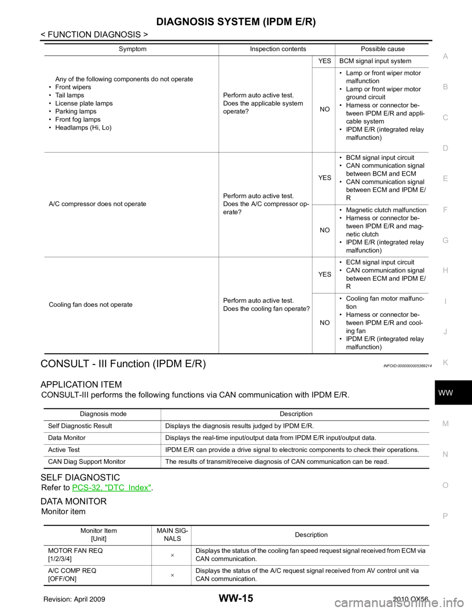
Any of the following components do not operate
• Front wipers
•Tail lamps
• License plate lamps
•Parking lamps
• Front fog lamps
• Headlamps (Hi, Lo) Perform auto active test.
Does the applicable system
operate?YES BCM signal input system
NO • Lamp or front wiper motor
malfunction
• Lamp or front wiper motor ground circuit
• Harness or connector be-
tween IPDM E/R and appli-
cable system
• IPDM E/R (integrated relay
malfunction)
A/C compressor does not operate Perform auto active test.
Does the A/C compressor op-
erate?YES
• BCM signal input circuit
• CAN communication signal
between BCM and ECM
• CAN communication signal between ECM and IPDM E/
R
NO • Magnetic clutch malfunction
• Harness or connector be-
tween IPDM E/R and mag-
netic clutch
• IPDM E/R (integrated relay malfunction)
Cooling fan does not operate Perform auto active test.
Does the cooling fan operate?YES
• ECM signal input circuit
• CAN communication signal
between ECM and IPDM E/
R
NO • Cooling fan motor malfunc-
tion
• Harness or connector be- tween IPDM E/R and cool-
ing fan
• IPDM E/R (integrated relay malfunction)
Symptom
Inspection contentsPossible cause
Diagnosis mode Description
Self Diagnostic Result Displays the diagnosis results judged by IPDM E/R.
Data Monitor Displays the real-time input/output data from IPDM E/R input/output data.
Active Test IPDM E/R can provide a drive signal to electronic components to check their operations.
CAN Diag Support Monitor The results of transmit/receive diagnosis of CAN communication can be read.
Monitor Item
[Unit] MAIN SIG-
NALS Description
MOTOR FAN REQ
[1/2/3/4] ×
Displays the status of the cooling fan speed request signal received from ECM via
CAN communication.
A/C COMP REQ
[OFF/ON] ×Displays the status of the A/C request signal received from AV control unit via
CAN communication.
Revision: April 20092010 QX56