2010 INFINITI QX56 ABS
[x] Cancel search: ABSPage 2221 of 4210
FSU-22
< DISASSEMBLY AND ASSEMBLY >
COIL SPRING AND SHOCK ABSORBER
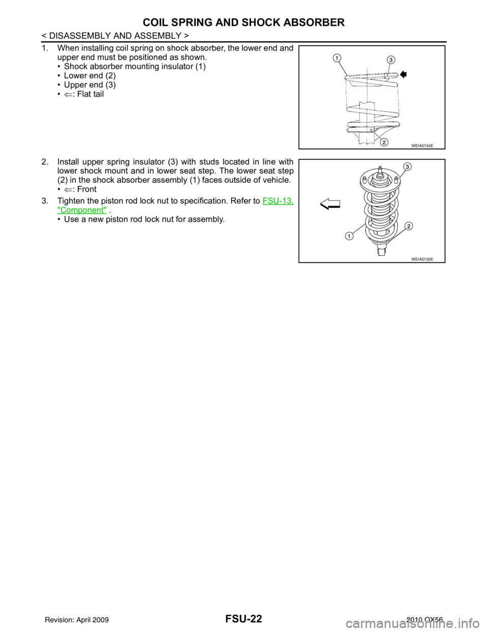
1. When installing coil spring on shock absorber, the lower end andupper end must be positioned as shown.
• Shock absorber mounting insulator (1)
• Lower end (2)
• Upper end (3)
•⇐ : Flat tail
2. Install upper spring insulator (3) with studs located in line with lower shock mount and in lower seat step. The lower seat step
(2) in the shock absorber assembly (1) faces outside of vehicle.
•⇐ : Front
3. Tighten the piston rod lock nut to specification. Refer to FSU-13,
"Component" .
• Use a new piston rod lock nut for assembly.
WEIA0154E
WEIA0155E
Revision: April 20092010 QX56
Page 2222 of 4210
SERVICE DATA AND SPECIFICATIONS (SDS)FSU-23
< SERVICE DATA AND SPECIFICATIONS (SDS)
C
DF
G H
I
J
K L
M A
B
FSU
N
O P
SERVICE DATA AND SPECIFICATIONS (SDS)
SERVICE DATA AND SPECIFICATIONS (SDS)
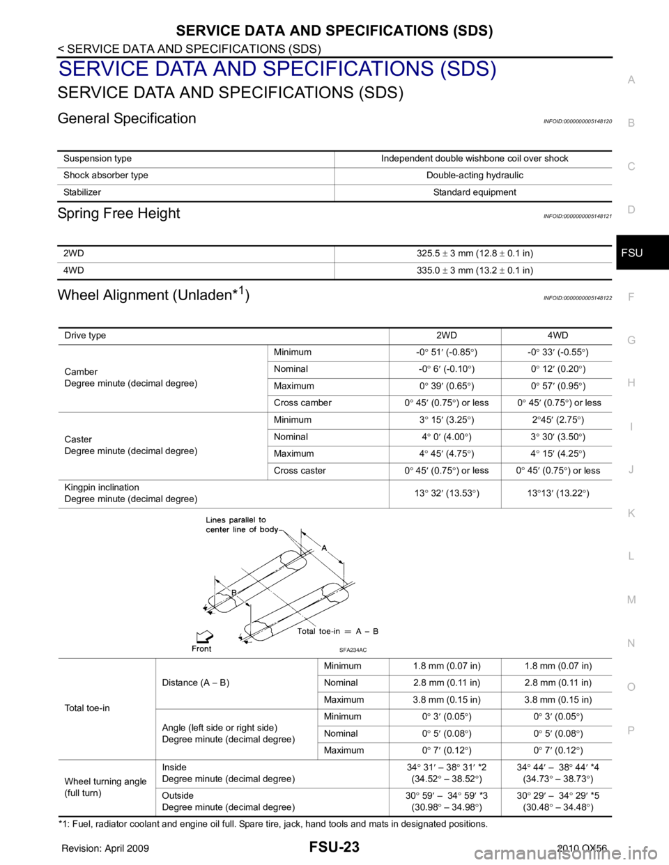
General SpecificationINFOID:0000000005148120
Spring Free HeightINFOID:0000000005148121
Wheel Alignment (Unladen*1)INFOID:0000000005148122
*1: Fuel, radiator coolant and engine oil full. Spare tire, jack, hand tools and mats in designated positions. Suspension type
Independent double wishbone coil over shock
Shock absorber type Double-acting hydraulic
Stabilizer Standard equipment
2WD325.5 ± 3 mm (12.8 ± 0.1 in)
4WD 335.0 ± 3 mm (13.2 ± 0.1 in)
Drive type 2WD 4WD
Camber
Degree minute (decimal degree) Minimum
-0° 51 ′ (-0.85 °)- 0° 33 ′ (-0.55 °)
Nominal -0° 6 ′ (-0.10 °)0 ° 12 ′ (0.20 °)
Maximum 0° 39 ′ (0.65 °)0 ° 57 ′ (0.95 °)
Cross camber 0° 45 ′ (0.75 °) or less 0 ° 45′ (0.75 °) or less
Caster
Degree minute (decimal degree) Minimum
3° 15 ′ (3.25 °)2 °45 ′ (2.75 °)
Nominal 4° 0 ′ (4.00 °)3 ° 30 ′ (3.50 °)
Maximum 4° 45 ′ (4.75 °)4 ° 15 ′ (4.25 °)
Cross caster 0° 45 ′ (0.75 °) or less 0
° 45 ′ (0
.75°) or less
Kingpin inclination
Degree minute (decimal degree) 13
° 32 ′ (13.53 °)1 3°13 ′ (13.22 °)
Total toe-in Distance (A
− B) Minimum
1.8 mm (0.07 in) 1.8 mm (0.07 in)
Nominal 2.8 mm (0.11 in) 2.8 mm (0.11 in)
Maximum 3.8 mm (0.15 in) 3.8 mm (0.15 in)
Angle (left side or right side)
Degree minute (decimal degree) Minimum
0° 3 ′ (0.05 °)0 ° 3 ′ (0.05 °)
Nominal 0° 5 ′ (0.08 °)0 ° 5 ′ (0.08 °)
Maximum 0° 7 ′ (0.12 °)0 ° 7 ′ (0.12 °)
Wheel turning angle
(full turn) Inside
Degree minute (decimal degree)
34
° 31 ′ – 38 ° 31 ′ *2
(34.52 ° – 38.52 °) 34
° 44 ′ – 38 ° 44 ′ *4
(34.73 ° – 38.73 °)
Ou t
side
Degree minute (decimal degree) 30
° 59 ′ – 34 ° 59 ′ *3
(30.98 ° – 34.98 °) 30
° 29 ′ – 34 ° 29 ′ *5
(30.48 ° – 34.48 °)
SFA234AC
Revision: April 20092010 QX56
Page 2240 of 4210

TERMINOLOGYGI-17
< HOW TO USE THIS MANUAL >
C
DE
F
G H
I
J
K L
M B
GI
N
O P
Exhaust gas recirculation control-BPT
valve EGRC-BPT valve
BPT valve
Exhaust gas recirculation control-solenoid
valve EGRC-solenoid valve
EGR control solenoid valve
Exhaust gas recirculation temperature sen-
sor EGRT sensorExhaust gas temperature sensor
EGR temperature sensor
Flash electrically erasable programmable
read only memory FEEPROM
***
Flash erasable programmable read only
memory FEPROM
***
Flexible fuel sensor FFS***
Flexible fuel system FF system***
Fuel pressure regulato r*** Pressure regulator
Fuel pressure regulator control solenoid
valve ***
PRVR control solenoid valve
Fuel trim FT***
Heated Oxygen sensor HO2S Exhaust gas sensor
Idle air control system IAC system Idle speed control
Idle air control valve-air regulato rIACV-air regulator Air regulator
Idle air control valve-auxiliary air control
valve IACV-AAC valve
Auxiliary air control (AAC) valve
Idle air control valve-FICD solenoid valve IACV-FICD solenoid valve FICD solenoid valve
Idle air control valve-idle up control sole-
noid valve IACV-idle up control solenoid valve Idle up control solenoid valve
Idle speed control-FI pot ISC-FI pot FI pot
Idle speed control system ISC system***
Ignition control IC***
Ignition control module ICM***
Indirect fuel injection system IFI system ***
Intake air IA Air
Intake air temperature sensor IAT sensor Air temperature sensor
Knock *** Detonation
Knock sensor KS Detonation sensor
Malfunction indicator lamp MIL Check engine light
Manifold absolute pressure MAP ***
Manifold absolute pressure sensor MAPS ***
Manifold differential pressure MDP ***
Manifold differential pressure sensor MDPS ***
Manifold su rface temperature MST ***
Manifold surface temperature sensor MSTS ***
Manifold vacuum zone MVZ ***
Manifold vacuum zone sensor MVZS***
Mass air flow sensor MAFS Air flow meter
Mixture control solenoid valve MC solenoid valveAir-fuel ratio control solenoid valve
Multiport fuel injection System MFI system Fuel injection control
NEW TERM
NEW ACRONYM /
ABBREVIATION OLD TERM
Revision: April 20092010 QX56
Page 2244 of 4210
IDENTIFICATION INFORMATIONGI-21
< FEATURES OF NEW MODEL >
C
DE
F
G H
I
J
K L
M B
GI
N
O P
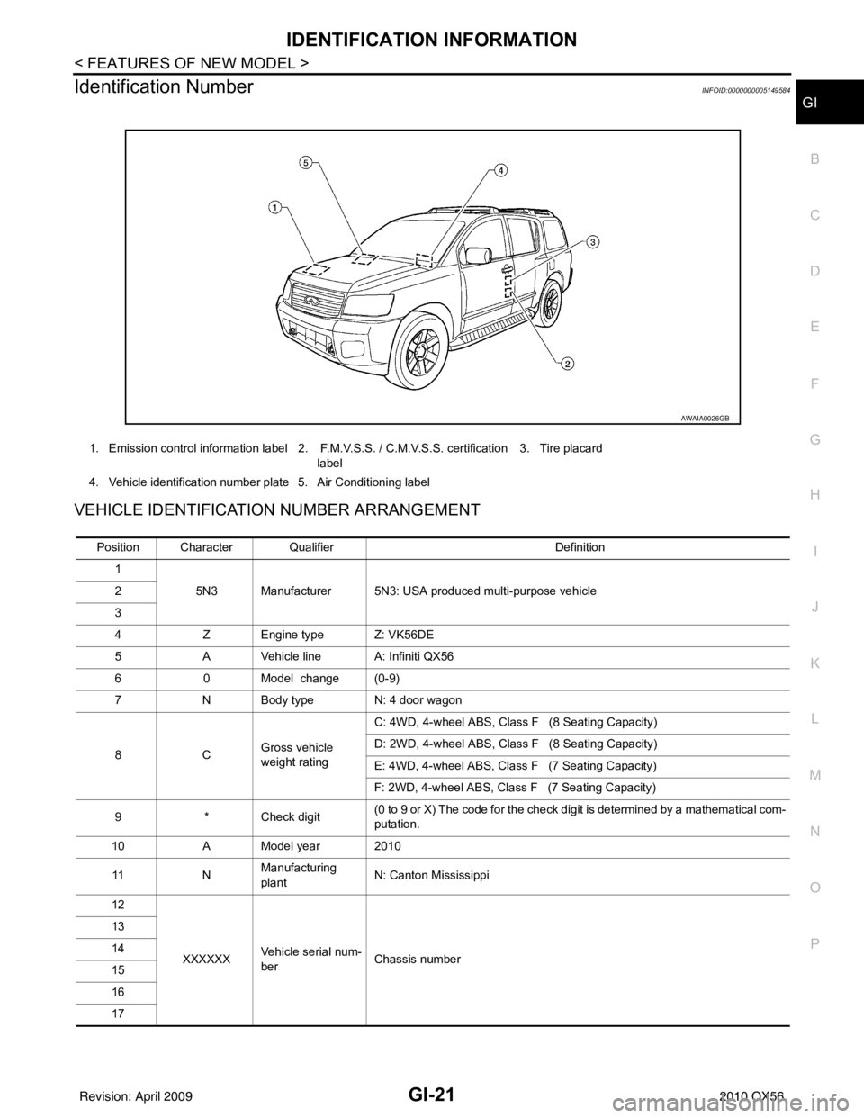
Identification NumberINFOID:0000000005149584
VEHICLE IDENTIFICATION NUMBER ARRANGEMENT
1. Emission control information label 2. F.M.V.S.S. / C.M.V.S.S. certification label3. Tire placard
4. Vehicle identification number plate 5. Air Conditioning label
AWAIA0026GB
Position Character Qualifier Definition
1 5N3 Manufacturer 5N3: USA produced multi-purpose vehicle
2
3
4 Z Engine type Z: VK56DE
5 A Vehicle line A: Infiniti QX56
6 0 Model change (0-9)
7 N Body type N: 4 door wagon
8C Gross vehicle
weight ratingC: 4WD, 4-wheel ABS, Class F (8 Seating Capacity)
D: 2WD, 4-wheel ABS, Class F (8 Seating Capacity)
E: 4WD, 4-wheel ABS, Class F (7 Seating Capacity)
F: 2WD, 4-wheel ABS, Class F (7 Seating Capacity)
9 * Check digit (0 to 9 or X) The code for the check digit is determined by a mathematical com-
putation.
10 A Model year 2010
11 NManufacturing
plant
N: Canton Mississippi
12
XXXXXX Vehicle serial num-
ber Chassis number
13
14
15
16
17
Revision: April 20092010 QX56
Page 2269 of 4210
GI-46
< BASIC INSPECTION >
CONSULT-III CHECKING SYSTEM
CONSULT-III CHECKING SYSTEM
DescriptionINFOID:0000000005149609
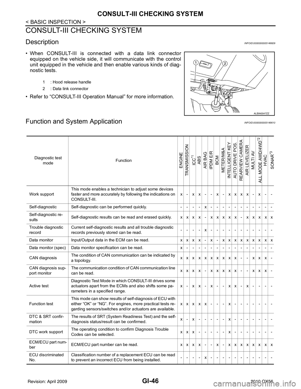
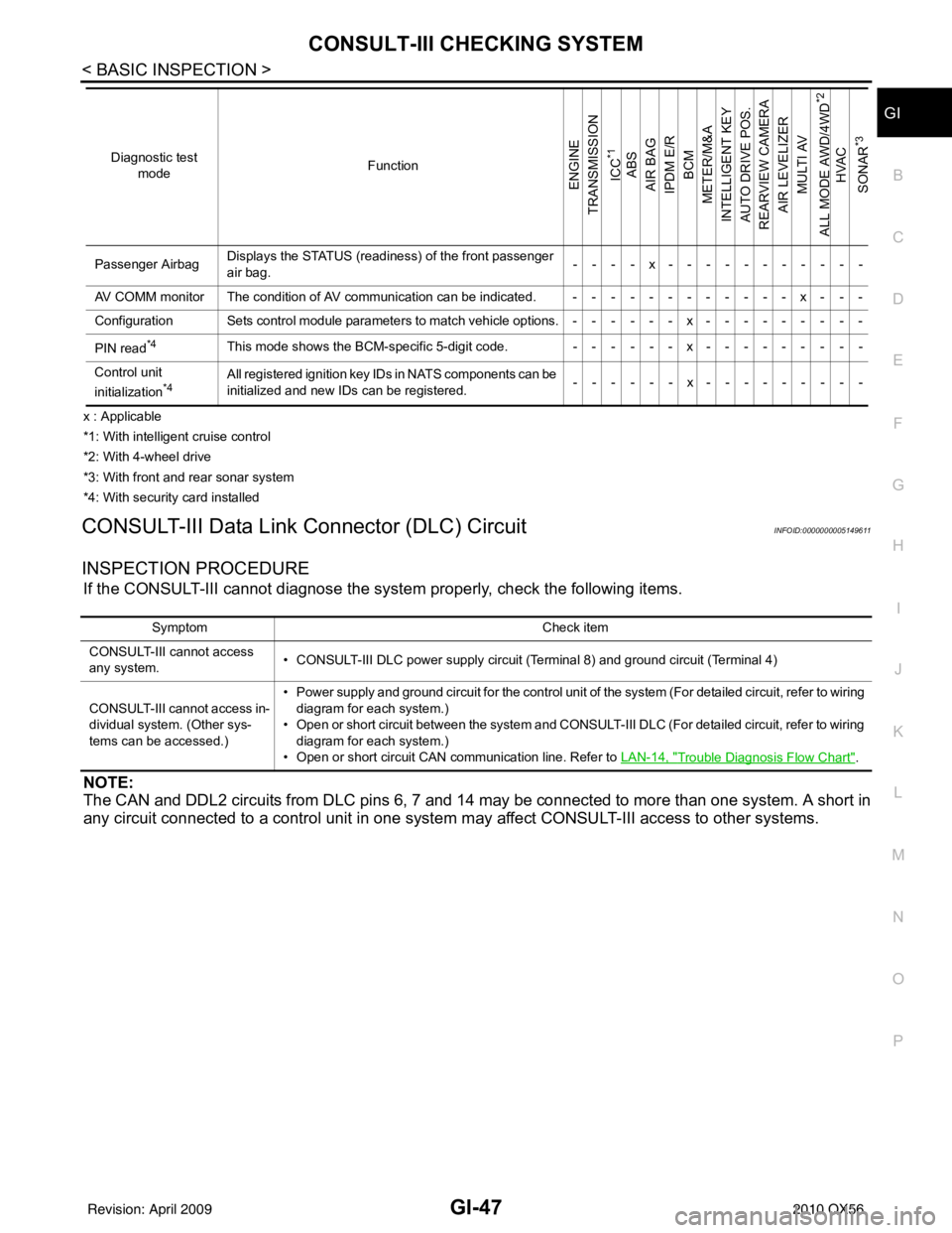
• When CONSULT-III is connected with a data link connectorequipped on the vehicle side, it will communicate with the control
unit equipped in the vehicle and then enable various kinds of diag-
nostic tests.
• Refer to “CONSULT-III Operation Manual” for more information.
Function and System ApplicationINFOID:0000000005149610
1 : Hood release handle
2 : Data link connector
ALBIA0047ZZ
Diagnostic test mode Function
ENGINE
TRANSMISSION
ICC
*1
ABS
AIR BAG
IPDM E/R
BCM
METER/M&A
INTELLIGENT KEY
AUTO DRIVE POS.
REARVIEW CAMERA
AIR LEVELIZER MULTI AV
ALL MODE AWD/4WD
*2
HVAC
SONAR
*3
Work support This mode enables a technician to adjust some devices
faster and more accurately by following the indications on
CONSULT-III. x- x x- - x- xxxx- x - -
Self-diagnostic Self-diagnostic can be performed quickly. ----x-----------
Self-diagnostic re-
sults Self-diagnostic results can be read and erased quickly. x x x x - x x x x x - x x x x x
Trouble diagnostic
record Current self-diagnostic results and all trouble diagnostic
records previously stored can be read.
--- - x--- - -------
Data monitor Input/Output data in the ECM can be read. xxx x- x- xxxxxxx xx
Data monitor (spec) Data monitor specification can be read. x---------------
CAN diagnosis The condition of CAN communication can be indicated by
a topology.
xxx xxxxxxx- - xx x-
CAN diagnosis sup-
port monitor The communication condition of CAN communication line
can be read.
xxx x- xxxxx- - xx x-
Active test Diagnostic Test Mode in wh
ich CONSULT-III drives some
actuators apart from the ECMs and also shifts some pa-
rameters in a specified range. x-xx-x--xx-x- - --
Function test This mode can show results of self-diagnosis of ECU with
either “OK” or “NG”. For engines, more practical tests re-
garding sensors/switches and/or actuators are available.
xxxxx---x-------
DTC & SRT confir-
mation The results of SRT (System Readiness Test) and the self-
diagnosis status/result can be confirmed.
x-x-----x-------
DTC work support The operating condition to confirm Diagnosis Trouble
Codes can be selected. xxx-----x-------
ECM/ECU part num-
ber ECM/ECU part number can be read.
xxx x- - x- xxxxxx xx
ECU discriminated
No. Classification number of a replacement ECU can be read
to prevent an incorrect ECU from being installed.
----x-----------
Revision: April 20092010 QX56
Page 2270 of 4210
CONSULT-III CHECKING SYSTEMGI-47
< BASIC INSPECTION >
C
DE
F
G H
I
J
K L
M B
GI
N
O P
x : Applicable
*1: With intelligent cruise control
*2: With 4-wheel drive
*3: With front and rear sonar system
*4: With security card installed
CONSULT-III Data Link Connector (DLC) CircuitINFOID:0000000005149611
INSPECTION PROCEDURE
If the CONSULT-III cannot diagnose the sys tem properly, check the following items.
NOTE:
The CAN and DDL2 circuits from DLC pins 6, 7 and 14 may be connected to more than one system. A short in
any circuit connected to a control unit in one system may affect CONSULT-III access to other systems.
Passenger AirbagDisplays the STATUS (readiness) of the front passenger
air bag. ----x-----------
AV COMM monitor The condition of AV communication can be indicated. ------------x---
Configuration Sets control module parameters to match vehicle options.------x---------
PIN read
*4This mode shows the BCM-specific 5-digit code. ------x---------
Control unit
initialization
*4All registered ignition key IDs in NATS components can be
initialized and new IDs can be registered. ------x---------
Diagnostic test
mode Function
ENGINE
TRANSMISSION
ICC
*1
ABS
AIR BAG
IPDM E/R BCM
METER/M&A
INTELLIGENT KEY
AUTO DRIVE POS.
REARVIEW CAMERA AIR LEVELIZER MULTI AV
ALL MODE AWD/4WD
*2
HVAC
SONAR
*3
Symptom Check item
CONSULT-III cannot access
any system. • CONSULT-III DLC power supply circuit (Terminal 8) and ground circuit (Terminal 4)
CONSULT-III cannot access in-
dividual system. (Other sys-
tems can be accessed.) • Power supply and ground circuit for the control unit of the system (For detailed circuit, refer to wiring
diagram for each system.)
• Open or short circuit between the system and CONSULT-III DLC (For detailed circuit, refer to wiring
diagram for each system.)
• Open or short circuit CAN communication line. Refer to LAN-14, "
Trouble Diagnosis Flow Chart".
Revision: April 20092010 QX56
Page 2296 of 4210
HA-4
< PRECAUTION >
PRECAUTIONS
5. When the repair work is completed, return the ignition switch to the ″LOCK ″ position before connecting
the battery cables. (At this time, the steering lock mechanism will engage.)
6. Perform a self-diagnosis check of a ll control units using CONSULT-III.
Precaution for Working with HFC-134a (R-134a)INFOID:0000000005147630
WARNING:
• CFC-12 (R-12) refrigerant and HFC-134a (R-134a) refr igerant are not compatible. If the refrigerants
are mixed compressor failure is likely to occur. Refer to HA-4, "
Contaminated Refrigerant". To deter-
mine the purity of HFC-134a (R-134a) in the vehicle and recovery tank, use recovery/recycling equip-
ment and refrigerant identifier.
• Use only specified oil for the HFC-134a (R-134a) A/C system and HFC-134a (R-134a) components. If
oil other than that specified is used, compressor failure is likely to occur.
• The specified HFC-134a (R-134a) oi l rapidly absorbs moisture from the atmosphere. The following
handling precautions must be observed:
- When removing refrigerant components from a vehicle, immediately cap (seal) the component to
minimize the entry of moisture from the atmosphere.
- When installing refrigerant co mponents to a vehicle, do not remove the caps (unseal) until just
before connecting the components. Connect all refrigerant loop components as quickly as possible
to minimize the entry of moisture into system.
- Only use the specified oil from a sealed container. Immediately reseal containers of oil. Without
proper sealing, oil will become moisture saturat ed and should not be used.
- Avoid breathing A/C refrigerant and oil vapor or mist. Exposure may irrita te eyes, nose and throat.
Remove HFC-134a (R-134a) from the A/C system usin g certified service equipment meeting require-
ments of SAE J2210 [HFC-134a (R-134a) recycling equipment], or J2209 [HFC-134a (R-134a) recovery
equipment]. If accidental system discharge occurs, ventilate work area before resuming service.
Additional health and safety in formation may be obtained from refrigerant and oil manufacturers.
- Do not allow A/C oil to come in contact with styrofoam parts. Damage may result.
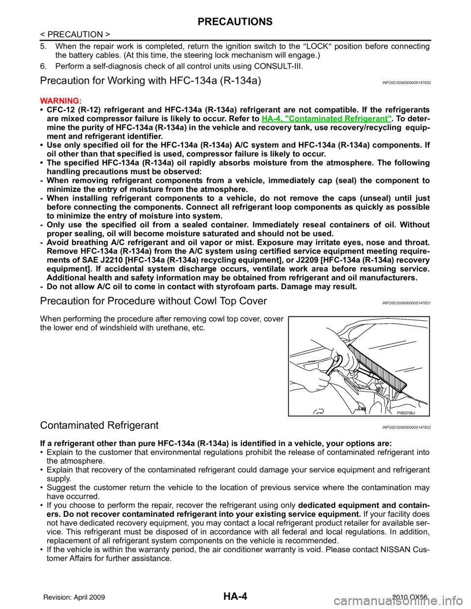
Precaution for Procedure without Cowl Top CoverINFOID:0000000005147631
When performing the procedure after removing cowl top cover, cover
the lower end of windshield with urethane, etc.
Contaminated RefrigerantINFOID:0000000005147632
If a refrigerant other than pure HFC-134a (R-134a) is identified in a vehicle, your options are:
• Explain to the customer that environmental regulations prohibit the release of contaminated refrigerant into
the atmosphere.
• Explain that recovery of the contaminated refri gerant could damage your service equipment and refrigerant
supply.
• Suggest the customer return the vehicle to the location of previous service where the contamination may have occurred.
• If you choose to perform the repair, recover the refrigerant using only dedicated equipment and contain- ers. Do not recover contamin ated refrigerant into your existing service equipment. If your facility does
not have dedicated recovery equipment, you may contact a local refrigerant product retailer for available ser-
vice. This refrigerant must be disposed of in acco rdance with all federal and local regulations. In addition,
replacement of all refrigerant system components on the vehicle is recommended.
• If the vehicle is within the warranty period, the air conditioner warranty is void. Please contact NISSAN Cus- tomer Affairs for further assistance.
PIIB3706J
Revision: April 20092010 QX56
Page 2461 of 4210
![INFINITI QX56 2010 Factory Service Manual PRECAUTIONSHAC-121
< PRECAUTION > [AUTOMATIC AIR CONDITIONER]
C
D
E
F
G H
J
K L
M A
B
HAC
N
O P
PRECAUTION
PRECAUTIONS
Precaution for Supplemental Restraint System (SRS) "AIR BAG" and "SEAT BELT
PRE INFINITI QX56 2010 Factory Service Manual PRECAUTIONSHAC-121
< PRECAUTION > [AUTOMATIC AIR CONDITIONER]
C
D
E
F
G H
J
K L
M A
B
HAC
N
O P
PRECAUTION
PRECAUTIONS
Precaution for Supplemental Restraint System (SRS) "AIR BAG" and "SEAT BELT
PRE](/manual-img/42/57032/w960_57032-2460.png)
PRECAUTIONSHAC-121
< PRECAUTION > [AUTOMATIC AIR CONDITIONER]
C
D
E
F
G H
J
K L
M A
B
HAC
N
O P
PRECAUTION
PRECAUTIONS
Precaution for Supplemental Restraint System (SRS) "AIR BAG" and "SEAT BELT
PRE-TENSIONER"
INFOID:0000000005197361
The Supplemental Restraint System such as “AIR BAG” and “SEAT BELT PRE-TENSIONER”, used along
with a front seat belt, helps to reduce the risk or severi ty of injury to the driver and front passenger for certain
types of collision. This system includes seat belt switch inputs and dual stage front air bag modules. The SRS
system uses the seat belt switches to determine the front air bag deployment, and may only deploy one front
air bag, depending on the severity of a collision and w hether the front occupants are belted or unbelted.
Information necessary to service the system safely is included in the SR and SB section of this Service Man-
ual.
WARNING:
• To avoid rendering the SRS inoper ative, which could increase the risk of personal injury or death in
the event of a collision which would result in air bag inflation, all maintenance must be performed by
an authorized NISSAN/INFINITI dealer.
• Improper maintenance, including in correct removal and installation of the SRS, can lead to personal
injury caused by unintentional act ivation of the system. For removal of Spiral Cable and Air Bag
Module, see the SR section.
• Do not use electrical test equipm ent on any circuit related to the SRS unless instructed to in this
Service Manual. SRS wiring harnesses can be identi fied by yellow and/or orange harnesses or har-
ness connectors.
PRECAUTIONS WHEN USING POWER TOOLS (AIR OR ELECTRIC) AND HAMMERS
WARNING:
• When working near the Airbag Diagnosis Sensor Un it or other Airbag System sensors with the Igni-
tion ON or engine running, DO NOT use air or el ectric power tools or strike near the sensor(s) with a
hammer. Heavy vibration could activate the sensor( s) and deploy the air bag(s), possibly causing
serious injury.
• When using air or electric power tools or hammers, always switch the Ignition OFF, disconnect the battery, and wait at least 3 minutes before performing any service.
Working with HFC-134a (R-134a)INFOID:0000000005147743
WARNING:
• CFC-12 (R-12) refrigerant and HFC-134a (R-134a) refr igerant are not compatible. If the refrigerants
are mixed compressor failure is likely to occur. Refer to HA-4, "
Contaminated Refrigerant". To deter-
mine the purity of HFC-134a (R-134a) in the vehic le and recovery tank, use Refrigerant Recovery/
Recycling Recharging equipment and Refrigerant Identifier.
• Use only specified oil for the HFC-134a (R-134a) A/C system and HFC-134a (R-134a) components. If oil other than that specified is used, compressor fa ilure is likely to occur.
• The specified HFC-134a (R-134a) oil rapidly absorb s moisture from the atmosphere. The following
handling precautions must be observed:
- When removing refrigerant components from a vehicle, immediately cap (seal) the component to
minimize the entry of mois ture from the atmosphere.
- When installing refrigerant components to a vehicle, do not remove the caps (unseal) until just
before connecting the co mponents. Connect all refrigerant lo op components as quickly as possible
to minimize the entry of moisture into system.
- Only use the specified oil from a sealed container. Immediately r eseal containers of oil. Without
proper sealing, oil will become moisture saturat ed and should not be used.
- Avoid breathing A/C refrigerant and oil vapor or mist. Exposure may irritate eyes, nose and throat.
Remove HFC-134a (R-134a) from the A/C system usi ng certified service equipment meeting require-
ments of SAE J2210 [HFC-134a (R-134a) recycling equipment], or J2209 [HFC-134a (R-134a) recy-
cling equipment], If accidental system discharge occurs, ventilate work area before resuming
service. Additional health and safety information may be obtained from refrigerant and oil manufac-
turers.
- Do not allow A/C oil to come in contact with styrofoam parts. Damage may result.
CONTAMINATED REFRIGERANT
Revision: April 20092010 QX56