2010 INFINITI QX56 ABS
[x] Cancel search: ABSPage 1816 of 4210
![INFINITI QX56 2010 Factory Service Manual ECM
EC-463
< ECU DIAGNOSIS > [VK56DE]
C
D
E
F
G H
I
J
K L
M A
EC
NP
O
*3: In Diagnostic Test
Mode II (Self-diagnostic results), this number is controlled by NISSAN.
*4: SRT code will not be set if t INFINITI QX56 2010 Factory Service Manual ECM
EC-463
< ECU DIAGNOSIS > [VK56DE]
C
D
E
F
G H
I
J
K L
M A
EC
NP
O
*3: In Diagnostic Test
Mode II (Self-diagnostic results), this number is controlled by NISSAN.
*4: SRT code will not be set if t](/manual-img/42/57032/w960_57032-1815.png)
ECM
EC-463
< ECU DIAGNOSIS > [VK56DE]
C
D
E
F
G H
I
J
K L
M A
EC
NP
O
*3: In Diagnostic Test
Mode II (Self-diagnostic results), this number is controlled by NISSAN.
*4: SRT code will not be set if the self-diagnostic result is NG.
*5: The troubleshooting for this DTC needs CONSULT-III.
*6: When the fail-safe operations for both self-diagnoses occur, the MIL illuminates.
*7: When the ECM is in the mode of displaying SRT status, MIL may flash. For the details, refer to "How to Display SRT Status".
*8: 2WD models
*9: Models with ICC
*10: Models without ICC
Emission-related Di agnostic InformationINFOID:0000000005149499
DTC AND 1ST TRIP DTC
The 1st trip DTC (whose number is the same as the DTC number) is displayed for the latest self-diagnostic
result obtained. If the ECM memory was cleared previous ly, and the 1st trip DTC did not reoccur, the 1st trip
DTC will not be displayed.
If a malfunction is detected during the 1st trip, the 1st trip DTC is stored in the ECM memory. The MIL will not
light up (two trip detection logic). If the same malfunc tion is not detected in the 2nd trip (meeting the required
driving pattern), the 1st trip DTC is cleared from the ECM memory. If the same malfunction is detected in the
2nd trip, both the 1st trip DTC and DTC are stored in t he ECM memory and the MIL lights up. In other words,
the DTC is stored in the ECM memory and the MIL lights up when the same malfunction occurs in two consec-
utive trips. If a 1st trip DTC is stored and a non-diagnostic operation is performed between the 1st and 2nd
trips, only the 1st trip DTC will continue to be stored. Fo r malfunctions that blink or light up the MIL during the
1st trip, the DTC and 1st trip DTC are stored in the ECM memory.
Procedures for clearing the DTC and the 1st trip DT C from the ECM memory are described in "HOW TO
ERASE EMISSION-RELATED DIAGNOSTIC INFORMATION".
For malfunctions in which 1st trip DTCs are displa yed, refer to "EMISSION-RELATED DIAGNOSTIC INFOR-
MATION ITEMS". These items are required by legal r egulations to continuously monitor the system/compo-
nent. In addition, the items monitored non-cont inuously are also displayed on CONSULT-III.
1st trip DTC is specified in Service $07 of SAE J1979. 1st trip DTC detection occurs without lighting up the MIL
and therefore does not warn the driver of a malfunction. However, 1st trip DTC detection will not prevent the
vehicle from being tested, for example during Inspection/Maintenance (I/M) tests.
When a 1st trip DTC is detected, check, print out or write down and erase (1st trip) DTC and Freeze Frame
data as specified in Work Flow procedure Step 2, refer to EC-8, "
Trouble Diagnosis Introduction". Then per-
form DTC Confirmation Procedure or Overall Function Che ck to try to duplicate the malfunction. If the mal-
function is duplicated, the item requires repair.
How to Read DTC and 1st Trip DTC
DTC and 1st trip DTC can be read by the following methods.
With CONSULT-III
With GST
CONSULT-III or GST (Generic Scan Tool ) Examples: P0340, P0850, P1148, etc.
These DTCs are prescribed by SAE J2012.
(CONSULT-III also displays the malfunctioning component or system.)
No Tools
The number of blinks of the MIL in the Diagnostic Test Mode II (Self-Diagnostic Results) indicates the DTC.
Example: 0340, 0850, 1148, etc.
These DTCs are controlled by NISSAN.
• 1st trip DTC No. is the same as DTC No.
• Output of a DTC indicates a malfunc tion. However, GST or the Diagnostic Test Mode II do not indi-
cate whether the malfunction is stil l occurring or has occurred in the past and has returned to nor-
mal. CONSULT-III can identify malfunction status as shown below. Therefore, using CONSULT-III (if
available) is recommended.
DTC or 1st trip DTC of a malfunction is display ed in SELF-DIAGNOSTIC RESULTS mode of CONSULT-III.
Time data indicates how many times the vehicle was driven after the last detection of a DTC.
If the DTC is being detected currently, the time data will be [0].
If a 1st trip DTC is stored in the ECM, the time data will be [1t].
FREEZE FRAME DATA AND 1ST TRIP FREEZE FRAME DATA
The ECM records the driving conditions such as fuel system status, calculated load value, engine coolant tem-
perature, short term fuel trim, long term fuel trim, engi ne speed, vehicle speed, absolute throttle position, base
fuel schedule and intake air temperature at the moment a malfunction is detected.
Revision: April 20092010 QX56
Page 1831 of 4210
![INFINITI QX56 2010 Factory Service Manual EC-478
< SYMPTOM DIAGNOSIS >[VK56DE]
ENGINE CONTROL SYSTEM SYMPTOMS
1 - 6: The numbers refer to the order of inspection.
(continued on next page)
SYSTEM — ENGINE MECHANICAL & OTHER
Mass air flow sen INFINITI QX56 2010 Factory Service Manual EC-478
< SYMPTOM DIAGNOSIS >[VK56DE]
ENGINE CONTROL SYSTEM SYMPTOMS
1 - 6: The numbers refer to the order of inspection.
(continued on next page)
SYSTEM — ENGINE MECHANICAL & OTHER
Mass air flow sen](/manual-img/42/57032/w960_57032-1830.png)
EC-478
< SYMPTOM DIAGNOSIS >[VK56DE]
ENGINE CONTROL SYSTEM SYMPTOMS
1 - 6: The numbers refer to the order of inspection.
(continued on next page)
SYSTEM — ENGINE MECHANICAL & OTHER
Mass air flow sensor circuit
1
12 2
222 2 EC-104,
EC-110
Engine coolant temperature sensor circuit
333
EC-121,
EC-129
Air fuel ratio (A/F ) sensor 1 circuit EC-137
,
EC-141
,
EC-145
,
EC-149
,
EC-382
Throttle position sensor circuit 22EC-125
,
EC-188
,
EC-306
,
EC-308
,
EC-374
Accelerator pedal position sensor circuit 3 2 1EC-284
,
EC-367
,
EC-370
,
EC-378
Knock sensor circuit 23EC-198
Crankshaft position sensor (POS) circuit 2 2 EC-201
Camshaft position sensor (PHASE) circuit 3 2 EC-205
Vehicle speed signal circuit2 3 33EC-275
Power steering pressu re sensor circuit 23 3 EC-281
ECM 22333333333 EC-284,
EC-286
Intake valve timing control solenoid valve cir-
cuit 32 13223 3
EC-101
Park/Neutral position (PNP) signal circuit3 3 3 33EC-292
Refrigerant pressure sensor circuit 233 4 EC-419
Electrical load signal circuit 3EC-394
Air conditioner circuit 223333333 3 2 HAC-25
ABS actuator and electric unit (control unit) 4 BRC-36
SYMPTOM
Refer-
ence page
HARD/NO START/RESTART (EXCP. HA)
ENGINE STALL
HESITATION/SURGING/FLAT SPOT
SPARK KNOCK/DETONATION
LACK OF POWER/POOR ACCELERATION
HIGH IDLE/LOW IDLE
ROUGH IDLE/HUNTING
IDLING VIBRATION
SLOW/NO RETURN TO IDLE
OVERHEATS/WATER TEMPERATURE HIGH
EXCESSIVE FUEL CONSUMPTION
EXCESSIVE OIL CONSUMPTION
BATTERY DEAD (UNDER CHARGE)
Warranty symptom code AA AB AC AD AE AF AG AH AJ AK AL AM HA
Revision: April 20092010 QX56
Page 1922 of 4210

CYLINDER HEADEM-71
< ON-VEHICLE REPAIR >
C
DE
F
G H
I
J
K L
M A
EM
NP
O
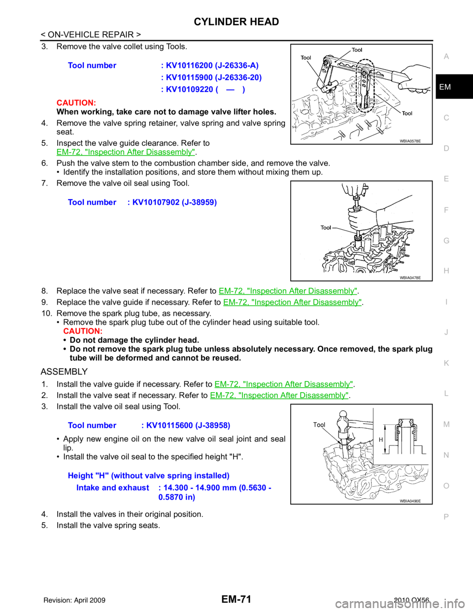
3. Remove the valve collet using Tools.
CAUTION:
When working, take care not to damage valve lifter holes.
4. Remove the valve spring retainer, valve spring and valve spring seat.
5. Inspect the valve guide clearance. Refer to EM-72, "
Inspection After Disassembly".
6. Push the valve stem to the combustion chamber side, and remove the valve. • Identify the installation positions, and store them without mixing them up.
7. Remove the valve oil seal using Tool.
8. Replace the valve seat if necessary. Refer to EM-72, "
Inspection After Disassembly".
9. Replace the valve guide if necessary. Refer to EM-72, "
Inspection After Disassembly".
10. Remove the spark plug tube, as necessary. • Remove the spark plug tube out of the cylinder head using suitable tool.
CAUTION:
• Do not damage the cylinder head.
• Do not remove the spark plug tube unless absolutely necessary. Once removed, the spark plug tube will be deformed and cannot be reused.
ASSEMBLY
1. Install the valve guide if necessary. Refer to EM-72, "Inspection After Disassembly".
2. Install the valve seat if necessary. Refer to EM-72, "
Inspection After Disassembly".
3. Install the valve oil seal using Tool.
• Apply new engine oil on the new valve oil seal joint and seallip.
• Install the valve oil seal to the specified height "H".
4. Install the valves in their original position.
5. Install the valve spring seats. Tool number
: KV10116200 (J-26336-A)
: KV10115900 (J-26336-20)
: KV10109220 ( — )
Tool number : KV10107902 (J-38959)
WBIA0578E
WBIA0478E
Tool number : KV10115600 (J-38958)
Height "H" (without valve spring installed) Intake and exhaust : 14.300 - 14.900 mm (0.5630 - 0.5870 in)
WBIA0490E
Revision: April 20092010 QX56
Page 2130 of 4210

EXL-154
< REMOVAL AND INSTALLATION >
LIGHTING & TURN SIGNAL SWITCH
LIGHTING & TURN SIGNAL SWITCH
Removal and InstallationINFOID:0000000005146704
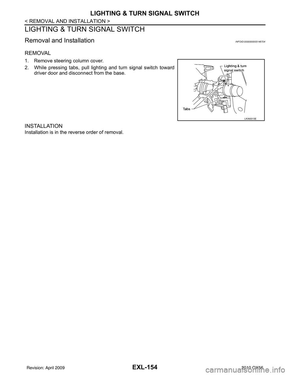
REMOVAL
1. Remove steering column cover.
2. While pressing tabs, pull lighting and turn signal switch toward
driver door and disconnect from the base.
INSTALLATION
Installation is in the reverse order of removal.
LKIA0013E
Revision: April 20092010 QX56
Page 2148 of 4210

FRONT BUMPEREXT-13
< SERVICE INFORMATION >
C
DE
F
G H
I
J
L
M A
B
EXT
N
O P
FRONT BUMPER
Removal and InstallationINFOID:0000000005147318
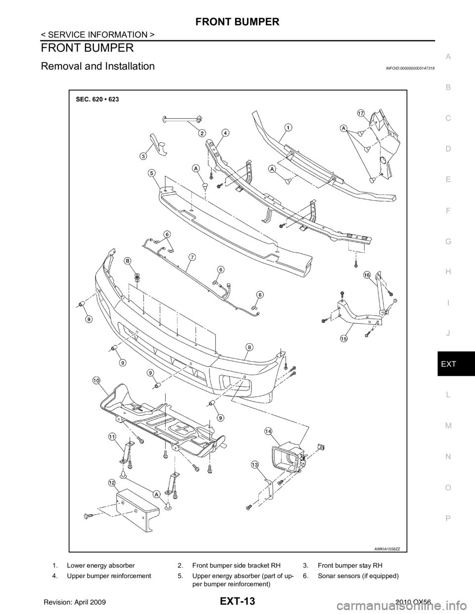
1. Lower energy absorber 2. Front bumper side bracket RH 3. Front bumper stay RH
4. Upper bumper reinforcement 5. Upper energy absorber (part of up- per bumper reinforcement) 6. Sonar sensors (if equipped)
AWKIA1559ZZ
Revision: April 20092010 QX56
Page 2149 of 4210

EXT-14
< SERVICE INFORMATION >
FRONT BUMPER
REMOVAL
1. Remove the side screws from the front fascia assembly.
2. Remove the screws from the front of fender protector. Refer to EXT-23
.
3. Remove the fog turn/fog lamp finisher and the fog turn/fog lamp. • Disconnect the harnesses.
4. Disconnect the sonar sensor, if equipped harness connector under the front fascia assembly.
5. Remove the fasteners, release the clips and remove the front fascia assembly.
6. Remove the plastic clips and remove the upper energy absorber.
7. Remove the upper bumper reinforcement.
8. Remove the plastic clips and remove the lower energy absorber.
9. Remove the front bumper stays and the front bumper side brackets, LH and RH.
10. Disconnect the sonar sensors, if equipped from the sonar sensor retainers, if equipped.
11. Remove the sonar sensors, if equipped and harness from the front fascia assembly. • Disconnect the sonar sensors, if equipped from the harness.
• Remove the sonar sensor retainers, if equipped from the front fascia assembly.
INSTALLATION
Installation is in the reverse order of removal.
7. Sonar sensor harness (if equipped) 8. Front fascia assembly 9. Sonar sensor retainers (if equipped)
10. Engine under cover 11. Front fascia bracket12. License plate bracket
13. Fog turn/fog lamp finisher LH/RH 14. Fog turn/fog lamp 15. Front bumper stay LH
16. Front bumper side bracket LH 17. Headlamp finisher (RH shown) A. Clip C103
B. Clip CS101
Revision: April 20092010 QX56
Page 2150 of 4210

REAR BUMPEREXT-15
< SERVICE INFORMATION >
C
DE
F
G H
I
J
L
M A
B
EXT
N
O P
REAR BUMPER
Removal and InstallationINFOID:0000000005147319
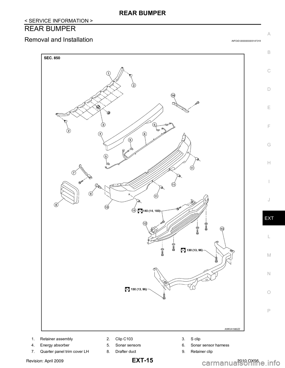
1. Retainer assembly 2. Clip C1033. S clip
4. Energy absorber 5. Sonar sensors6. Sonar sensor harness
7. Quarter panel trim cover LH 8. Drafter duct 9. Retainer clip
AWKIA1560ZZ
Revision: April 20092010 QX56
Page 2151 of 4210

EXT-16
< SERVICE INFORMATION >
REAR BUMPER
REMOVAL
1. Remove the rear combination lamps LH and RH. Refer to EXL-158, "Removal and Installation".
2. Remove the rear fascia assembly screws under the rear combination lamps LH and RH.
3. Remove the quarter panel trim covers LH and RH.
4. Disconnect the sonar sensor harness c onnector under the rear fascia assembly.
5. Release the retainer clips on both sides of the rear fascia assembly with a 1/4 turn and top S clips and remove the fascia assembly.
6. Detach the I-key antenna from the energy absorber.
7. Remove the energy absorber.
8. Remove the reinforcement assembly.
9. Remove the nuts and remove the retainer assembly. • Remove the S clips from the retainer assembly.
10. Disconnect the sonar sensors from the sonar sensor retainers.
11. Remove the sonar sensors and harness from the rear fascia assembly. • Disconnect the sonar sensors from the harness.
• Remove the sonar sensor retainers from the rear fascia assembly.
12. Remove the bolts on each side of the tow hitch and remove the tow hitch.
13. Remove the drafter duct from under the LH quarter pane, if necessary.
INSTALLATION
Installation is in the reverse order of removal.
10. Rear fascia assembly 11. Sonar sensor retainer12. Reinforcement assembly
13. Tow hitch 14. Quarter panel trim cover RH
Revision: April 20092010 QX56