Page 17 of 104

Operation in standing water
Ingestion of water into the diesel engine can result in immediate and
severe damage to the engine. If driving through water, slow down to
avoid splashing water into the intake. If the engine stalls, and ingestion
of water into the engine is suspected, do not try to restart the engine.
Consult your dealer for service immediately.
Winter grille cover (F-Super Duty only) (if equipped)
If your vehicle includes a winter grille cover, it will enhance heater
performance and will reduce the amount of time it takes to warm the
inside of your vehicle in extremely cold conditions (below 0°F [-18°C]).
The winter grille cover installs over the outside of the grille of your
vehicle and restricts the air flowing to the engine compartment by
covering the radiator grille openings.
Usage guidelines
The winter grille cover should only be used while operating your vehicle
in extremely cold temperatures or in heavy snow for extended periods of
time. In these temperatures, the vehicle does not need a large amount of
air to properly cool the engine. During periods of operation when more
airflow is required to cool the vehicle, the winter grille cover should not
be used. The following usage guidelines will allow adequate airflow for
proper radiator and air cooler performance.
Driving
17
2010 Econoline(eco)
Supplement(supplement), 1st Printing
USA(fus)
Page 18 of 104
. Use of the cover in these conditions could cause your vehicle
to overheat. If this happens while the cover is being use")
•Do not use the winter grille cover when temperatures are above 50°F
(10°C). Use of the cover in these conditions could cause your vehicle
to overheat. If this happens while the cover is being used, remove the
cover and store properly.
•Do not use the winter grille cover above 32°F (0°C) if towing a trailer.
The added power needed to tow a trailer requires the radiator grille to
have full airflow under all conditions. Your vehicle may overheat if the
cover is used while towing a trailer.
•Do not modify the winter grille cover. The winter grille cover does not
block some sections of the front of the vehicle because these openings
are needed to provide enough airflow to the radiator and air cooler in
extremely cold temperatures.
Installation instructions
The “Installation Instructions” included with your winter grille cover
packaging explain how to install and remove your vehicle’s winter grille
cover. When installing or removing the winter grille cover, refer to the
“Usage guidelines”listed previously. When you first attempt to fit the
winter grille cover, it may appear to be undersized. This is due to the
nature of the special vinyl, which will stretch during installation to
ensure a tight fit. For this reason, the initial installation of the winter
grille cover is best performed when the cover is warm.
Engine block heater (if equipped)
Refer to theDrivingchapter in theOwner’s Guide.
Rapid Heat supplemental heating system (if equipped)
The optional Rapid Heat feature is an electrically powered device that is
designed to provide supplemental heat during engine warm up. For
maximum effectiveness mid to low blower speed is recommended during
initial warm up. When operating in automatic mode (when equipped) the
climate control unit will determine the appropriate blower speed for
existing conditions.
Note:Additional aftermarket electrical loads operated during engine
warm up may impact the performance of the Rapid heat supplemental
heater.
Driving
18
2010 Econoline(eco)
Supplement(supplement), 1st Printing
USA(fus)
Page 19 of 104

If your vehicle is equipped with dual
fuel tanks, you will have a selector
control, located to the right of the
steering wheel, which allows you to
draw f")
DUAL FUEL TANK SELECTOR CONTROL (IF EQUIPPED)
If your vehicle is equipped with dual
fuel tanks, you will have a selector
control, located to the right of the
steering wheel, which allows you to
draw fuel from either tank. Your fuel
gauge will display the amount of
fuel in the currently selected tank.
Fuel level indication is delayed for several minutes when the tank
selector switch is actuated. Fuel level indication can be obtained
immediately by turning off and restarting the engine.
TRAILER TOWING
Refer to yourOwner’s Guidefor full details on towing a trailer.
Trailer towing tables - E-Series
Engine Rear axle
ratioMaximum GCWR -
lbs. (kg)Maximum
trailer weight -
lbs. (kg)
E-350 Regular Van (9500 GVWR)
6.0L 3.55 16000 (7257) 9500 (4309)
6.0L 4.10 20000 (9072) 10000 (4536)
E-350 Extended/RV Van (9500 GVWR)
6.0L 3.55 16000 (7257) 9400 (4264)
6.0L 4.10 20000 (9072) 10000 (4536)
E-350 Regular Wagon (12–passenger) (8950 GVWR)
6.0L 3.55 16000 (7257) 8900 (4037)
6.0L 4.10 20000 (9072) 10000 (4536)
138” Wheelbase 9900 GVWR E-350 Cutaway with Single Rear
Wheels (SRW)
6.0L 4.10 20000 (9072) 10000 (4536)
Driving
19
2010 Econoline(eco)
Supplement(supplement), 1st Printing
USA(fus)
Page 20 of 104
Maximum
trailer weight -
lbs. (kg)
138” Wheelbase 10050 GVWR E-350 Cutaway with Single Rear
Wheels (SRW)
6.0L 4.10 20000 (9072) 10000 (4536)
138” Whee")
Engine Rear axle
ratioMaximum GCWR -
lbs. (kg)Maximum
trailer weight -
lbs. (kg)
138” Wheelbase 10050 GVWR E-350 Cutaway with Single Rear
Wheels (SRW)
6.0L 4.10 20000 (9072) 10000 (4536)
138” Wheelbase 10000 GVWR E-350 Cutaway with Dual Rear
Wheels (DRW)
6.0L 4.10 20000 (9072) 10000 (4536)
138” Wheelbase 11500 GVWR E-350 Cutaway with Dual Rear
Wheels (DRW)
6.0L 4.10 20000 (9072) 10000 (4536)
158” Wheelbase 10050 GVWR E–350 Cutaway with Single Rear
Wheels (SRW)
6.0L 4.10 20000 (9072) 10000 (4536)
158” Wheelbase 10000 GVWR E–350 Cutaway with Dual Rear
Wheels (DRW)
6.0L 4.10 20000 (9072) 10000 (4536)
158” Wheelbase 11500 GVWR E–350 Cutaway with Dual Rear
Wheels (DRW)
6.0L 4.10 20000 (9072) 10000 (4536)
158” Wheelbase 12500 GVWR E–350 Cutaway with Dual Rear
Wheels (DRW)
6.0L 4.10 20000 (9072) 10000 (4536)
176” Wheelbase 10000 GVWR E–350 Cutaway with Dual Rear
Wheels (DRW)
6.0L 4.10 20000 (9072) 10000 (4536)
176” Wheelbase 12500 GVWR E–350 Cutaway with Dual Rear
Wheels (DRW)
6.0L 4.10 20000 (9072) 10000 (4536)
158” Wheelbase 13990 GVWR E–450 Cutaway with Dual Rear
Wheels (DRW)
6.0L 4.10 20000 (9072) 10000 (4536)
Driving
20
2010 Econoline(eco)
Supplement(supplement), 1st Printing
USA(fus)
Page 21 of 104
Maximum
trailer weight -
lbs. (kg)
158” Wheelbase 14500 GVWR E–450 Cutaway with Dual Rear
Wheels (DRW)
6.0L 4.10 20000 (9072) 10000 (4536)
176” Whee")
Engine Rear axle
ratioMaximum GCWR -
lbs. (kg)Maximum
trailer weight -
lbs. (kg)
158” Wheelbase 14500 GVWR E–450 Cutaway with Dual Rear
Wheels (DRW)
6.0L 4.10 20000 (9072) 10000 (4536)
176” Wheelbase 13990 GVWR E–450 Cutaway with Dual Rear
Wheels (DRW)
6.0L 4.10 20000 (9072) 10000 (4536)
176” Wheelbase 14500 GVWR E–450 Cutaway with Dual Rear
Wheels (DRW)
6.0L 4.10 20000 (9072) 10000 (4536)
Trailer towing tables - F-Super Duty
Maximum GCWR - lb (kg.)
Engine Rear axle
ratioManual
transmissionAutomatic
transmission
F–250/F–350 Single Rear Wheel (SRW) Pick-up
6.4L 3.31 — 23000 (10433)
6.4L 3.55 23000 (10433) 23000 (10433)
F–350 Single Rear Wheel (SRW) Chassis Cab
6.4L 3.73 — 23000 (10433)
F–350 Dual Rear Wheel (DRW) Pick-up
6.4L 3.73/4.10 23500 (10659) —
6.4L 3.73 — 23500 (10659)
6.4L 4.10 — 26000 (11793)
F–350 Dual Rear Wheel (DRW) Chassis Cab
6.4L 3.73/4.10 23500 (10659) 23500 (10659)
F–450 Pick-up
6.4L 4.30 27000 (12247) 33000 (14969)
F–450 Chassis Cab
6.4L 4.30 26000 (11793) 26000 (11793)
6.4L* 4.30 — 30000 (13608)
6.4L* 4.88 28000 (12701) —
Driving
21
2010 Econoline(eco)
Supplement(supplement), 1st Printing
USA(fus)
Page 22 of 104

Engine Rear axle
ratioManual
transmissionAutomatic
transmission
F–550 Chassis Cab
6.4L 4.30/4.88 26000 (11793) 26000 (11793)
6.4L* 4.88 28000 (12701) 33000 (14969)
* With hig")
Maximum GCWR - lb (kg.)
Engine Rear axle
ratioManual
transmissionAutomatic
transmission
F–550 Chassis Cab
6.4L 4.30/4.88 26000 (11793) 26000 (11793)
6.4L* 4.88 28000 (12701) 33000 (14969)
* With high capacity trailer tow package; see rear axle label to identify
actual vehicle content.
Integrated hitch rating
The standard integrated hitch has two ratings depending on mode of
operation:
•Weight carrying- requires a draw bar and hitch ball. The draw bar
supports all the vertical tongue load of the trailer.
•Weight distributing- requires an aftermarket weight distributing
system which includes draw bar, hitch ball, spring bars and snap-up
brackets. The vertical tongue load of the trailer is distributed between
the truck and the trailer by this system.
Hitch TypeMaximum
Gross Trailer
Weight-lb
(kg)Maximum
Tongue Weight
- lb (kg)
F–250/350 DRW
Pick-ups 2.5” ID
without adapter
(requires 2.5”
drawbar)Weight carrying 8000 (3629) 800 (363)
Weight
distributing15000 (6804) 1500 (680)
F–250/350 DRW
Pick-ups 2.5” ID
with adapter*
(requires 2”
drawbar)Weight carrying 6000 (2721) 600 (272)
Weight
distributing12500 (5670) 1250 (567)
All SRW
Pick-ups 2”
receiverWeight carrying 6000 (2721) 600 (272)
Weight
distributing12500 (5670) 1250 (567)
Driving
22
2010 Econoline(eco)
Supplement(supplement), 1st Printing
USA(fus)
Page 23 of 104
Hitch TypeMaximum
Gross Trailer
Weight-lb
(kg)Maximum
Tongue Weight
- lb (kg)
F–450 DRW
Pick-ups 2.5” ID
without adapter
(requires 2.5”
drawbar)Weight carrying 8000 (3629) 800 (363)
Weight
distributing16000 (7258) 1600 (726)
F–450 DRW
Pick-ups 2.5” ID
with adapter*
(requires 2”
drawbar)Weight carrying 6000 (2721) 600 (272)
Weight
distributing12500 (5670) 1250 (567)
WARNING:Towing trailers beyond the maximum tongue weight
exceeds the limit of the towing system and could result in
vehicle structural damage, loss of vehicle control and personal injury.
* Trailer hitch adapter is available from Ford dealers (Part number:
5C3Z-19H282–A).
Driving
23
2010 Econoline(eco)
Supplement(supplement), 1st Printing
USA(fus)
Page 24 of 104

The following procedure is for E-Series vehicles only. F-Super
Duty vehicles equipped with the 6.4L diesel engine can be jump
started using the same procedur")
JUMP STARTING YOUR VEHICLE (E-SERIES ONLY)
The following procedure is for E-Series vehicles only. F-Super
Duty vehicles equipped with the 6.4L diesel engine can be jump
started using the same procedure as a gasoline engine; refer to
yourOwner’s Guidefor the jump starting procedure.
WARNING:The gases around the battery can explode if
exposed to flames, sparks, or lit cigarettes. An explosion could
result in injury or vehicle damage.
WARNING:Batteries contain sulfuric acid which can burn skin,
eyes and clothing, if contacted.
Do not attempt to push-start your vehicle. Automatic
transmissions do not have push-start capability; damage to the
automatic transmission may result.
Preparing your vehicle
When the batteries are disconnected or new batteries are installed, the
transmission must relearn its shift strategy. As a result, the transmission
may have firm and/or soft shifts. This operation is considered normal and
will not affect function or durability of the transmission. Over time, the
adaptive learning process will fully update transmission operation.
1.Use only a 12–volt supply to start your vehicle.
2. Do not disconnect the batteries of the disabled vehicle as this could
damage the vehicle’s electrical system.
3. Park the booster vehicle close to the passenger side of the disabled
vehicle making sure the two vehiclesdo nottouch. Set the parking
brake on both vehicles.
Note:This vehicle has two frame-mounted batteries located on the
passenger side frame rail, behind the front passenger door. A battery
positive (+) jumper stud is located on the frame rail behind the rear
most battery box.
Roadside Emergencies
24
2010 Econoline(eco)
Supplement(supplement), 1st Printing
USA(fus)
 1
1 2
2 3
3 4
4 5
5 6
6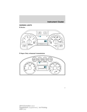 7
7 8
8 9
9 10
10 11
11 12
12 13
13 14
14 15
15 16
16 17
17 18
18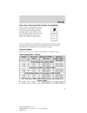 19
19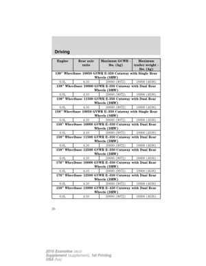 20
20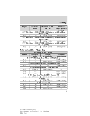 21
21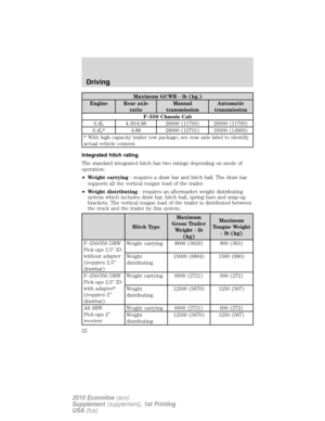 22
22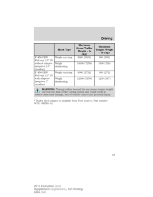 23
23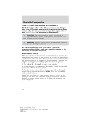 24
24 25
25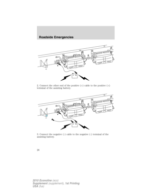 26
26 27
27 28
28 29
29 30
30 31
31 32
32 33
33 34
34 35
35 36
36 37
37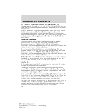 38
38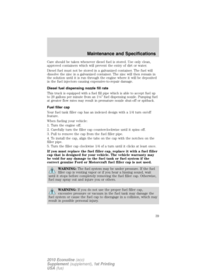 39
39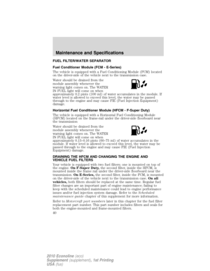 40
40 41
41 42
42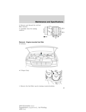 43
43 44
44 45
45 46
46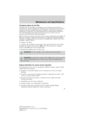 47
47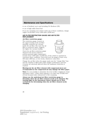 48
48 49
49 50
50 51
51 52
52 53
53 54
54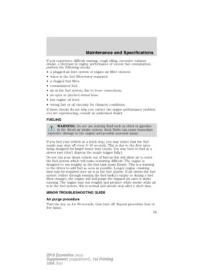 55
55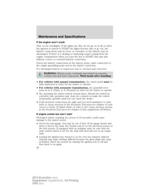 56
56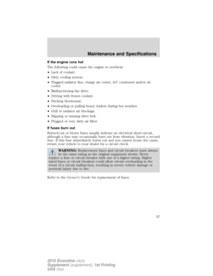 57
57 58
58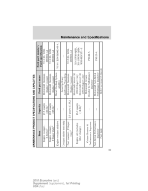 59
59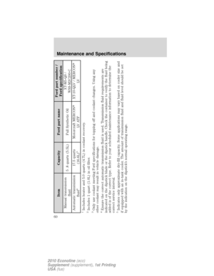 60
60 61
61 62
62 63
63 64
64 65
65 66
66 67
67 68
68 69
69 70
70 71
71 72
72 73
73 74
74 75
75 76
76 77
77 78
78 79
79 80
80 81
81 82
82 83
83 84
84 85
85 86
86 87
87 88
88 89
89 90
90 91
91 92
92 93
93 94
94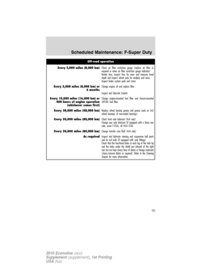 95
95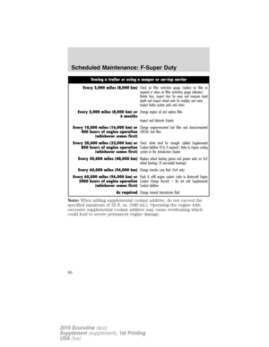 96
96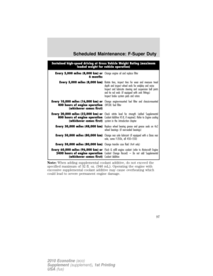 97
97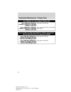 98
98 99
99 100
100 101
101 102
102 103
103Maximum
Tongue Weight
- lb (kg)
F–450 DRW
Pick-ups 2.5” ID
without adapter
(requires 2.5”
drawbar)Weight carrying 8000 (3629) 800 (363)
Weight
distr")