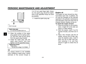
Page 25 of 84
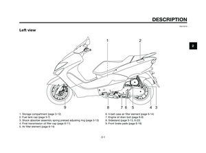
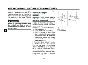
EAU13432
Catalytic converter
This model is equipped with a cataly-
tic converter in the exhaust system.
EWA10861
s s
WARNING
The exhaust system is hot after
operation. To prevent a fire hazard
or burns:
●Do not park the vehicle near
possible fire hazards such as
grass or other materials that
easily burn.
●Park the motorcycle in a place
where pedestrians or children
are not likely to touch the hot
exhaust system.
●Make sure that the exhaust
system has cooled down befo-
re doing any maintenance
work.
●Do not allow the engine to idle
more than a few minutes. Long
idling can cause a build-up of
heat.
ECA10701
NOTICE
Use only unleaded gasoline. The
use of leaded gasoline will cause
unrepairable damage to the cataly-
tic converter.
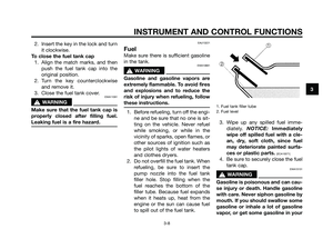
EAU13891
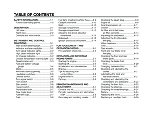
Seat
To open the seat
1. Insert the key in the lock, and
then turn it as shown.
1. Open.
2. Fold the seat up.
1. Seat
1
1
INSTRUMENT AND CONTROL FUNCTIONS
3-10
3
5D8-F8199-E1.QXD 10/7/08 07:39 Página 25
Page 26 of 84
To close the seat
1. Fold the seat down, and then
push it down to lock it in place.
2. Remove the key.
TIP
Make sure that the seat is properly
secured before riding.
EAU14541
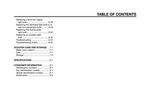
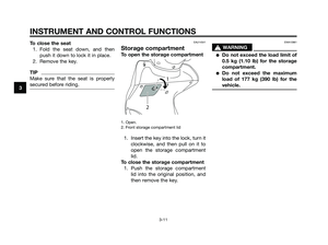
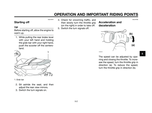
Storage compartment
To open the storage compartment
1. Open.
2. Front storage compartment lid
1. Insert the key into the lock, turn it
clockwise, and then pull on it to
open the storage compartment
lid.
To close the storage compartment
1. Push the storage compartment
lid into the original position, and
then remove the key.
EWA10961
s s
WARNING
●Do not exceed the load limit of
0.5 kg (1.10 lb) for the storage
compartment.
●Do not exceed the maximum
load of 177 kg (390 lb) for the
vehicle.
2
1
INSTRUMENT AND CONTROL FUNCTIONS
3-11
3
5D8-F8199-E1.QXD 10/7/08 07:39 Página 26
Page 27 of 84
.
EWA10961
s s
WARNING
●Do not exceed the load limit of
10 kg (22 lb) for the stora")
EAUM1191
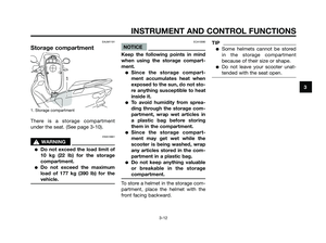
Storage compartment
1. Storage compartment
There is a storage compartment
under the seat. (See page 3-10).
EWA10961
s s
WARNING
●Do not exceed the load limit of
10 kg (22 lb) for the storage
compartment.
●Do not exceed the maximum
load of 177 kg (390 lb) for the
vehicle.
ECA10080
NOTICE
Keep the following points in mind
when using the storage compart-
ment.
●Since the storage compart-
ment accumulates heat when
exposed to the sun, do not sto-
re anything susceptible to heat
inside it.
●To avoid humidity from sprea-
ding through the storage com-
partment, wrap wet articles in
a plastic bag before storing
them in the compartment.
●Since the storage compart-
ment may get wet while the
scooter is being washed, wrap
any articles stored in the com-
partment in a plastic bag.
●Do not keep anything valuable
or breakable in the storage
compartment.
To store a helmet in the storage com-
partment, place the helmet with the
front facing backward.
TIP
●Some helmets cannot be stored
in the storage compartment
because of their size or shape.
●Do not leave your scooter unat-
tended with the seat open.
1
INSTRUMENT AND CONTROL FUNCTIONS
3-12
3
5D8-F8199-E1.QXD 10/7/08 07:39 Página 27
Page 28 of 84

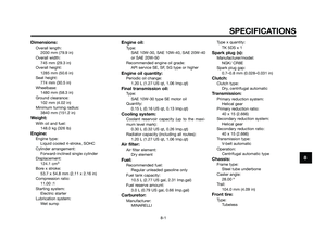
EAU14881
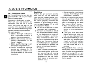
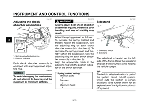
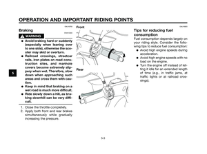
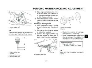
Adjusting the shock
absorber assemblies
1. Spring preload adjusting ring
2. Position indicator
Each shock absorber assembly is
equipped with a spring preload adjus-
ting ring.
ECA10101
NOTICE
To avoid damaging the mechanism,
do not attempt to turn beyond the
maximum or minimum settings.
EWA10210
s s
WARNING
Always adjust both shock absorber
assemblies equally, otherwise poor
handling and loss of stability may
result.
Adjust the spring preload as follows.
To increase the spring preload and
thereby harden the suspension, turn
the adjusting ring on each shock
absorber assembly in direction (a). To
decrease the spring preload and the-
reby soften the suspension, turn the
adjusting ring on each shock absor-
ber assembly in direction (b).
Align the appropriate notch in the
adjusting ring with the position indica-
tor on the shock absorber.
EAU15301
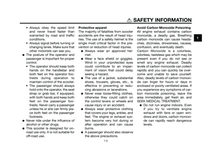
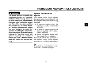
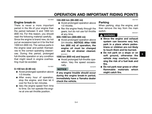
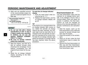
Sidestand
1. Sidestand switch
2. Sidestand
The sidestand is located on the left
side of the frame. Raise the sidestand
or lower it with your foot while holding
the vehicle upright.
TIP
The built-in sidestand switch is part of
the ignition circuit cut-off system,
which cuts the ignition in certain
situations. (See further down for an
explanation of the ignition circuit cut-
off system.)
1
2
Spring preload setting:
Minimum (soft):
1
Standard:
2
Maximum (hard):
4
21
ba
2
431
INSTRUMENT AND CONTROL FUNCTIONS
3-13
3
5D8-F8199-E1.QXD 10/7/08 07:39 Página 28
Page 29 of 84
, otherwise the
sidestand could contact the ground
a")
EWA10240
s s
WARNING
The vehicle must not be ridden with
the sidestand down, or if the sides-
tand cannot be properly moved up
(or does not stay up), otherwise the
sidestand could contact the ground
and distract the operator, resulting
in a possible loss of control. Yama-
ha’s ignition circuit cut-off system
has been designed to assist the
operator in fulfilling the responsibi-
lity of raising the sidestand before
starting off. Therefore, check this
system regularly as described
below and have a Yamaha dealer
repair it if it does not function pro-
perly.
EAU15362
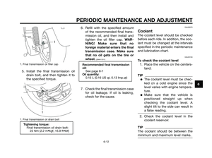
Ignition circuit cut-off
system
The ignition circuit cut-off system
(comprising the sidestand switch and
brake light switches) has the following
functions.
●It prevents starting when the
sidestand is up, but neither brake
is applied.
●It prevents starting when either
brake is applied, but the sides-
tand is still down.
●It cuts the running engine when
the sidestand is moved down.
Periodically check the operation of
the ignition circuit cut-off system
according to the following procedure.
TIP
This check is most reliable if perfor-
med with a warmed-up engine.
INSTRUMENT AND CONTROL FUNCTIONS
3-14
3
5D8-F8199-E1.QXD 10/7/08 07:39 Página 29
Page 30 of 84

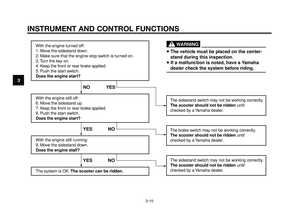
With the engine turned off:
1. Move the sidestand down.
2. Make sure that the engine stop switch is turned on.
3. Turn the key on.
4. Keep the front or rear brake applied.
5. Push the start switch.
Does the engine start?
With the engine still off:
6. Move the sidestand up.
7. Keep the front or rear brake applied.
8. Push the start switch.
Does the engine start?
With the engine still running:
9. Move the sidestand down.
Does the engine stall?
The system is OK. The scooter can be ridden.The sidestand switch may not be working correctly.
The scooter should not be ridden until
checked by a Yamaha dealer.
The sidestand switch may not be working correctly.
The scooter should not be ridden until
checked by a Yamaha dealer.
YES NO YES NO NO YES
The brake switch may not be working correctly.
The scooter should not be ridden until
checked by a Yamaha dealer.
• The vehicle must be placed on the center-
stand during this inspection.
• If a malfunction is noted, have a Yamaha
dealer check the system before riding.
WARNING
INSTRUMENT AND CONTROL FUNCTIONS
3-15
3
5D8-F8199-E1.QXD 10/7/08 07:39 Página 30
Page 31 of 84
FOR YOUR SAFETY – PRE-OPERATION CHECKS
4-1
4
EAU15595
Inspect your vehicle each time you use it to make sure the vehicle is in safe operating condition. Always follow the ins-
pection and maintenance procedures and schedules described in the Owner’s Manual.
EWA11151
s s
WARNING
Failure to inspect or maintain the vehicle properly increases the possibility of an accident or equipment dama-
ge. Do not operate the vehicle if you find any problem. If a problem cannot be corrected by the procedures pro-
vided in this manual, have the vehicle inspected by a Yamaha dealer.
Before using this vehicle, check the following points:
5D8-F8199-E1.QXD 10/7/08 07:39 Página 31
Page 32 of 84

FOR YOUR SAFETY – PRE-OPERATION CHECKS
4-2
4
EAU15605
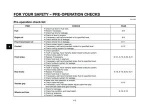
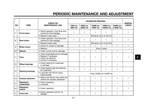
Pre-operation check list
ITEM CHECKS PAGE
• Check fuel level in fuel tank.
Fuel• Refuel if necessary.3-8
• Check fuel line for leakage.
• Check oil level in engine.
Engine oil• If necessary, add recommended oil to specified level. 6-9
• Check vehicle for oil leakage.
Final transmission oil• Check vehicle for oil leakage. 6-11
• Check coolant level in reservoir.
Coolant• If necessary, add recommended coolant to specified level. 6-12
• Check cooling system for leakage.
• Check operation.
• If soft or spongy, have Yamaha dealer bleed hydraulic system.
• Check brake pads for wear.
Front brake• Replace if necessary. 6-18 , 6-19, 6-20, 6-21
• Check fluid level in reservoir.
• If necessary, add recommended brake fluid to specified level.
• Check hydraulic system for leakage.
• Check operation.
• If soft or spongy, have Yamaha dealer bleed hydraulic system.
• Check brake pads for wear.
Rear brake• Replace if necessary. 6-18, 6-19, 6-20, 6-21
• Check fluid level in reservoir.
• If necessary, add recommended brake fluid to specified level.
• Check hydraulic system for leakage.
• Make sure that operation is smooth.
Throttle grip• Check cable free play. 6-15
• If necessary, have Yamaha dealer adjust cable free play
and lubricate cable and grip housing.
• Check for damage.
Wheels and tires• Check tire condition and tread depth. 6-16, 6-18
• Check air pressure.
• Correct if necessary.
5D8-F8199-E1.QXD 10/7/08 07:39 Página 32