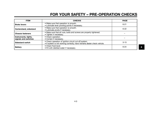
Page 49 of 84

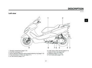
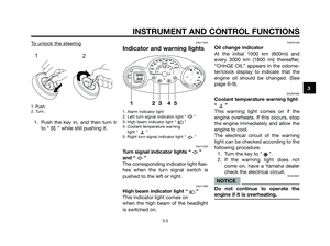
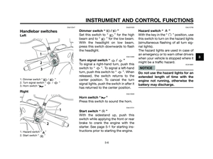
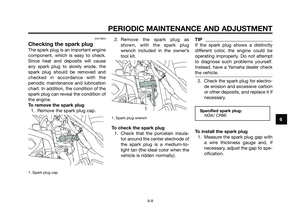
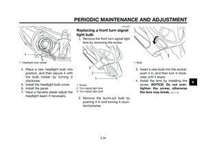
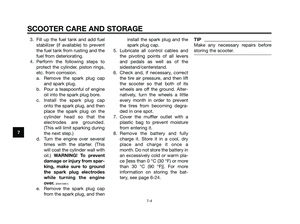
1. Final transmission oil filler cap
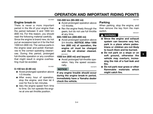
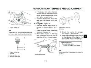
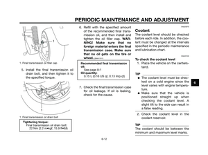
5. Install the final transmission oil
drain bolt, and then tighten it to
the specified torque.
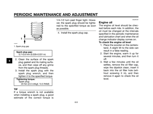
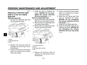
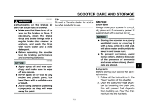
1. Final transmission oil drain bolt
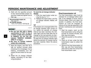
6. Refill with the specified amount
of the recommended final trans-
mission oil, and then install and
tighten the oil filler cap. WAR-
NING! Make sure that no
foreign material enters the final
transmission case. Make sure
that no oil gets on the tire or
wheel.
[EWA11311]
7. Check the final transmission case
for oil leakage. If oil is leaking,
check for the cause.
EAU20070
Coolant
The coolant level should be checked
before each ride. In addition, the coo-
lant must be changed at the intervals
specified in the periodic maintenance
and lubrication chart.
EAU20103
To check the coolant level
1. Place the vehicle on the centers-
tand.
TIP
●The coolant level must be chec-
ked on a cold engine since the
level varies with engine tempera-
ture.
●Make sure that the vehicle is
positioned straight up when
checking the coolant level. A
slight tilt to the side can result in
a false reading.
2. Check the coolant level in the
coolant reservoir.
TIP
The coolant should be between the
minimum and maximum level marks.
Recommended final transmission
oil:
See page 8-1
Oil quantity:
0.15 L (0.16 US qt, 0.13 Imp.qt)
Tightening torque:
Final transmission oil drain bolt:
22 Nm (2.2 m•kgf, 15.9 ft•lbf)
1
1
PERIODIC MAINTENANCE AND ADJUSTMENT
6-12
6
5D8-F8199-E1.QXD 10/7/08 07:39 Página 49
Page 50 of 84
, remove
the reservoir cap, add coolant")
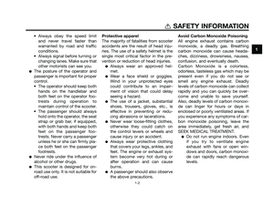
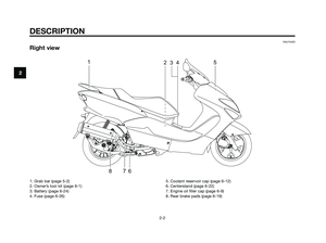
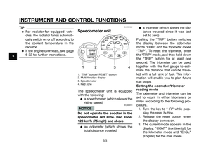
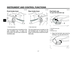
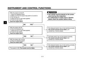
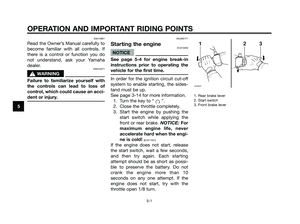
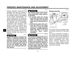
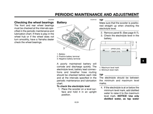
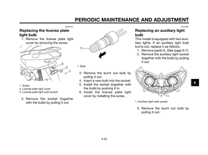
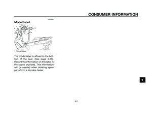
1. Coolant level check window
2. Maximum level mark
3. Minimum level mark
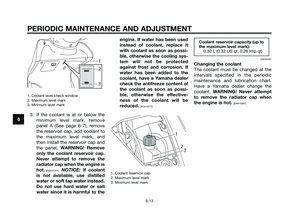
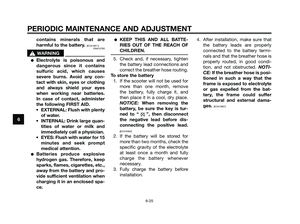
3. If the coolant is at or below the
minimum level mark, remove
panel A (See page 6-7), remove
the reservoir cap, add coolant to
the maximum level mark, and
then install the reservoir cap and
the panel. WARNING! Remove
only the coolant reservoir cap.
Never attempt to remove the
radiator cap when the engine is
hot.
[EWA15161]. NOTICE: If coolant
is not available, use distilled
water or soft tap water instead.
Do not use hard water or salt
water since it is harmful to theengine. If water has been used
instead of coolant, replace it
with coolant as soon as possi-
ble, otherwise the cooling sys-
tem will not be protected
against frost and corrosion. If
water has been added to the
coolant, have a Yamaha dealer
check the antifreeze content of
the coolant as soon as possi-
ble, otherwise the effective-
ness of the coolant will be
reduced.
[ECA10472]
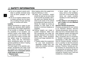
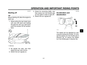
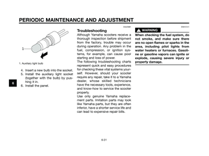
1. Coolant reservoir cap
2. Maximum level mark
3. Minimum level mark
EAU33031
Changing the coolant
The coolant must be changed at the
intervals specified in the periodic
maintenance and lubrication chart.
Have a Yamaha dealer change the
coolant. WARNING! Never attempt
to remove the radiator cap when
the engine is hot.
[EWA10381]
Coolant reservoir capacity (up to
the maximum level mark):
0.30 L (0.32 US qt, 0.26 Imp.qt)
23
1
MAXMAX
MINMIN
2 1
3
PERIODIC MAINTENANCE AND ADJUSTMENT
6-13
6
5D8-F8199-E1.QXD 10/7/08 07:39 Página 50
Page 51 of 84

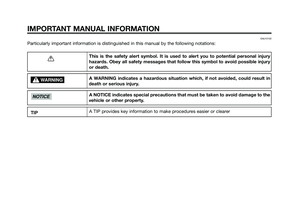
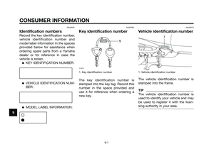
EAUM1321
Air filter and V-belt case air
filter elements
The air filter and the V-belt case air fil-
ter elements should be cleaned at the
intervals specified in the periodic
maintenance and lubrication chart.
Clean both filter elements more fre-
quently if you are riding in unusually
wet or dusty areas.
Cleaning the air filter element
1. Place the scooter on the centers-
tand.
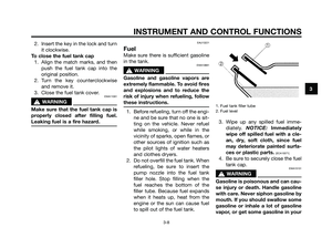
2. Remove the air filter case cover
by removing the screw.
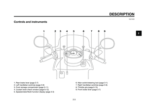
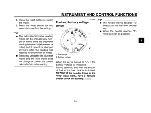
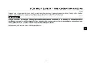
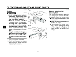
1. Screw
2. Air filter case cover
3. Pull the air filter element out.
1. Air filter element
4. Lightly tap the air filter element to
remove most of the dust and dirt,
and then blow the remaining dirt
out with compressed air.
5. Check the air filter element for
damage and replace it if neces-
sary.
6. Insert the air filter element into
the air filter case.
7. Install the air filter case cover by
installing the screw.Cleaning the V-belt case air filter
element
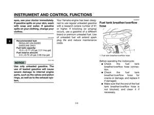
1. Remove the V-belt case air filter
cover by removing the screws.
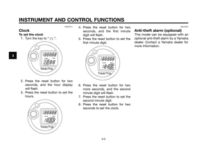
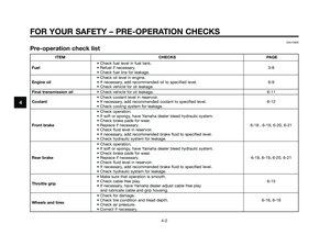
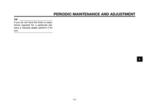
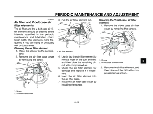
1. Screw
2. V-belt case air filter cover
2. Remove the air filter element, and
then blow out the dirt with com-
pressed air as shown.
1
2
1
1
2
PERIODIC MAINTENANCE AND ADJUSTMENT
6-14
6
5D8-F8199-E1.QXD 10/7/08 07:39 Página 51
Page 52 of 84

1. V-belt case air filter element
3. Check the air filter element for
damage and replace it if neces-
sary.
4. Install the air filter element with
the colored side facing outward.
5. Install the V-belt case air filter
cover by installing the screws.
NOTICE: Make sure that each
filter element is properly sea-
ted in its case. The engine
should never be operated wit-
hout the filter elements insta-
lled, otherwise the piston(s)
and/or cylinder(s) may become
excessively worn.
[ECA10531]EAU21300
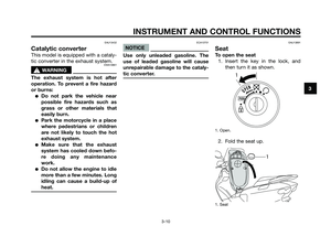
Adjusting the carburetor
The carburetor is an important part of
the engine and requires very sophisti-
cated adjustment. Therefore, all car-
buretor adjustments should be left to
a Yamaha dealer, who has the neces-
sary professional knowledge and
experience.
EAU21370
Adjusting the throttle cable
free play
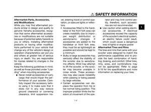
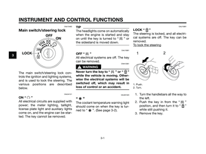
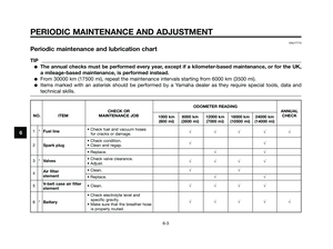
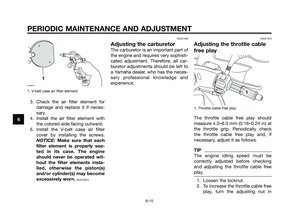
1. Throttle cable free play
The throttle cable free play should
measure 4.0–6.0 mm (0.16–0.24 in) at
the throttle grip. Periodically check
the throttle cable free play and, if
necessary, adjust it as follows.
TIP
The engine idling speed must be
correctly adjusted before checking
and adjusting the throttle cable free
play.
1. Loosen the locknut.
2. To increase the throttle cable free
play, turn the adjusting nut in
1
1
ZAUM0706
PERIODIC MAINTENANCE AND ADJUSTMENT
6-15
6
5D8-F8199-E1.QXD 10/7/08 07:39 Página 52
Page 53 of 84
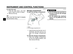
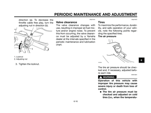
. To decrease the
throttle cable free play, turn the
adjusting nut in direction (b).
1. Locknut
2. Adjusting nut
3. Tighten the locknut.
EAU21401
Valve clearance
The valve clearance chang")
direction (a). To decrease the
throttle cable free play, turn the
adjusting nut in direction (b).
1. Locknut
2. Adjusting nut
3. Tighten the locknut.
EAU21401
Valve clearance
The valve clearance changes with
use, resulting in improper air-fuel mix-
ture and/or engine noise. To prevent
this from occurring, the valve clearan-
ce must be adjusted by a Yamaha
dealer at the intervals specified in the
periodic maintenance and lubrication
chart.
EAU21872
Tires
To maximize the performance, durabi-
lity, and safe operation of your vehi-
cle, note the following points regar-
ding the specified tires.
Tire air pressure
The tire air pressure should be chec-
ked and, if necessary, adjusted befo-
re each ride.
EWA10501
s s
WARNING
Operation of this vehicle with
improper tire pressure may cause
severe injury or death from loss of
control.
●The tire air pressure must be
checked and adjusted on cold
tires (i.e., when the temperatu-
ZAUM0053
a
b
21
PERIODIC MAINTENANCE AND ADJUSTMENT
6-16
6
5D8-F8199-E1.QXD 10/7/08 07:39 Página 53
Page 54 of 84
.
●The tire air pressure must be
adjusted in accordance with
the riding speed and with the
total weight of rider, passenger,
cargo, and accessories app")
re of the tires equals the
ambient temperature).
●The tire air pressure must be
adjusted in accordance with
the riding speed and with the
total weight of rider, passenger,
cargo, and accessories appro-
ved for this model.
EWA10511
s s
WARNING
Never overload your vehicle. Ope-
ration of an overloaded vehicle
could cause an accident.
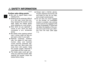
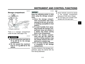
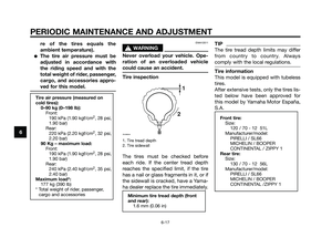
Tire inspection
1. Tire tread depth
2. Tire sidewall
The tires must be checked before
each ride. If the center tread depth
reaches the specified limit, if the tire
has a nail or glass fragments in it, or if
the sidewall is cracked, have a Yama-
ha dealer replace the tire immediately.
TIP
The tire tread depth limits may differ
from country to country. Always
comply with the local regulations.
Tire information
This model is equipped with tubeless
tires.
After extensive tests, only the tires lis-
ted below have been approved for
this model by Yamaha Motor España,
S.A.
Front tire:
Size:
120 / 70 - 12 51L
Manufacturer/model:
PIRELLI / SL66
MICHELIN / BOOPER
CONTINENTAL / ZIPPY 1
Rear tire:
Size:
130 / 70 - 12 56L
Manufacturer/model:
PIRELLI / SL66
MICHELIN / BOOPER
CONTINENTAL /ZIPPY 1
Minimum tire tread depth (front
and rear):
1.6 mm (0.06 in)
1
2
ZAUM0054
Tire air pressure (measured on
cold tires):
0–90 kg (0–198 lb):
Front:
190 kPa (1.90 kgf/cm
2, 28 psi,
1.90 bar)
Rear:
220 kPa (2.20 kgf/cm
2, 32 psi,
2.20 bar)
90 Kg – maximum load:
Front:
190 kPa (1.90 kgf/cm
2, 28 psi,
1.90 bar)
Rear:
240 kPa (2.40 kgf/cm
2, 35 psi,
2.40 bar)
Maximum load*:
177 kg (390 lb)
* Total weight of rider, passenger,
cargo and accessories
PERIODIC MAINTENANCE AND ADJUSTMENT
6-17
6
5D8-F8199-E1.QXD 10/7/08 07:39 Página 54
Page 55 of 84

EWA10470
s s
WARNING
●Have a Yamaha dealer replace
excessively worn tires. Besides
being illegal, operating the
vehicle with excessively worn
tires decreases riding stability
and can lead to loss of control.
●The replacement of all wheel
and brake related parts, inclu-
ding the tires, should be left to
a Yamaha dealer, who has the
necessary professional know-
ledge and experience.
EAU21960
Cast wheels
To maximize the performance, durabi-
lity, and safe operation of your vehi-
cle, note the following points regar-
ding the specified wheels.
●The wheel rims should be chec-
ked for cracks, bends or warpage
before each ride. If any damage
is found, have a Yamaha dealer
replace the wheel. Do not
attempt even the smallest repair
to the wheel. A deformed or crac-
ked wheel must be replaced.
●The wheel should be balanced
whenever either the tire or wheel
has been changed or replaced.
An unbalanced wheel can result
in poor performance, adverse
handling characteristics, and a
shortened tire life.
●Ride at moderate speeds after
changing a tire since the tire sur-
face must first be “broken in” for
it to develop its optimal characte-
ristics.
EAU33453
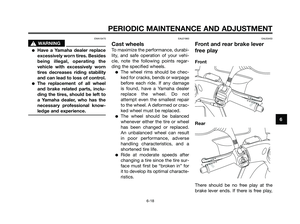
Front and rear brake lever
free play
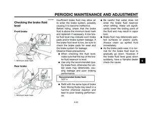
Front
Rear
There should be no free play at the
brake lever ends. If there is free play,
PERIODIC MAINTENANCE AND ADJUSTMENT
6-18
6
5D8-F8199-E1.QXD 10/7/08 07:39 Página 55
Page 56 of 84

have a Yamaha dealer inspect the
brake system.
EWA14211
s s
WARNING
A soft or spongy feeling in the bra-
ke lever can indicate the presence
of air in the hydraulic system. If the-
re is air in the hydraulic system,
have a Yamaha dealer bleed the
system before operating the vehi-
cle. Air in the hydraulic system will
diminish the braking performance,
which may result in loss of control
and an accident.
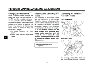
EAU22390
Checking the front and rear
brake pads
The front and rear brake pads must
be checked for wear at the intervals
specified in the periodic maintenance
and lubrication chart.
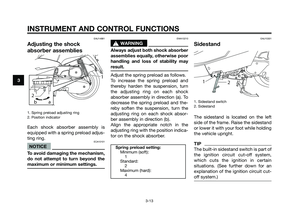
EAU22430
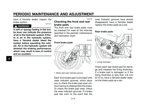
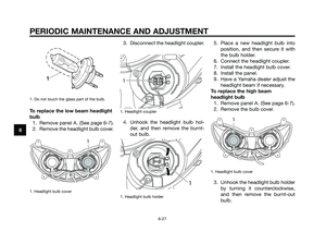
Front brake pads
1. Brake pad wear indicator groove
Each front brake pad is provided with
wear indicator grooves, which allow
you to check the brake pad wear wit-
hout having to disassemble the brake.
To check the brake pad wear, check
the wear indicator grooves. If a brake
pad has worn to the point that thewear indicator grooves have almost
disappeared, have a Yamaha dealer
replace the brake pads as a set.
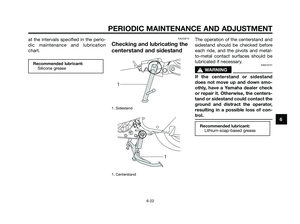
EAU22500
Rear brake pads
1. Lining thickness
Check each rear brake pad for dama-
ge and measure the lining thickness.
If a brake pad is damaged or if the
lining thickness is less than 3.8 mm
(0.15 in), have a Yamaha dealer repla-
ce the brake pads as a set.
1
11
PERIODIC MAINTENANCE AND ADJUSTMENT
6-19
6
5D8-F8199-E1.QXD 10/7/08 07:39 Página 56