Page 2048 of 2453
5AT-32
Line Pressure Test
AUTOMATIC TRANSMISSION
7. Line Pressure Test
A: MEASUREMENT
NOTE:
If the clutch or brake shows a sign of slippage, or
shifting interval is not correct, check the line pres-
sure.
•Excessive shock during up-shift may be due to
the line pressure being too high.
•Slippage or inability to operate the vehicle may,
in most cases, be due to loss of oil pressure for the
operation of clutch, brake or control valve.
1) Set the vehicle on a lift.
2) Remove the under cover.
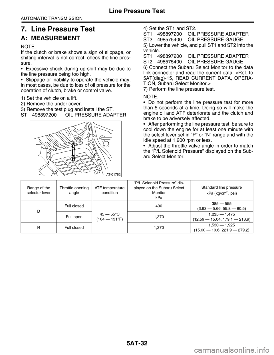
3) Remove the test plug and install the ST.
ST 498897200 OIL PRESSURE ADAPTER
4) Set the ST1 and ST2.
ST1 498897200 OIL PRESSURE ADAPTER
ST2 498575400 OIL PRESSURE GAUGE
5) Lower the vehicle, and pull ST1 and ST2 into the
vehicle.
ST1 498897200 OIL PRESSURE ADAPTER
ST2 498575400 OIL PRESSURE GAUGE
6) Connect the Subaru Select Monitor to the data
link connector and read the current data.
5AT(diag)-15, READ CURRENT DATA, OPERA-
TION, Subaru Select Monitor.>
7) Perform the line pressure test.
NOTE:
•Do not perform the line pressure test for more
than 5 seconds at a time. Doing so will make the
engine oil and ATF deteriorate and the clutch and
brake to be adversely affected.
•After performing the line pressure test, be sure to
cool down the engine for at least one minute with
the select lever set in “P” or “N” range and with the
idle speed at 1,200 rpm or less.
•Adjust the throttle valve angle in order to match
the “P/L Solenoid Pressure” displayed on the Sub-
aru Select Monitor.
AT-01752
Range of the
selector lever
Throttle opening
angle
AT F t e m p e r a t u r e
condition
“P/L Solenoid Pressure” dis-
played on the Subaru Select
Monitor
kPa
Standard line pressure
kPa (kg/cm2, psi)
D
Full closed
45 — 55°C
(104 — 131°F)
490385 — 555
(3.93 — 5.66, 55.8 — 80.5)
Full open 1,3701,235 — 1,475
(12.59 — 15.04, 179.1 — 213.9)
RFull closed 1,3701,530 — 1,925
(15.60 — 19.6, 221.9 — 279.2)
Page 2049 of 2453
5AT-33
Transfer Clutch Pressure Test
AUTOMATIC TRANSMISSION
8. Transfer Clutch Pressure
Test
A: INSPECTION
1) Lift-up the vehicle.
2) Remove the bolts holding the heat shield cover,
and move the heat shield cover to the rear.
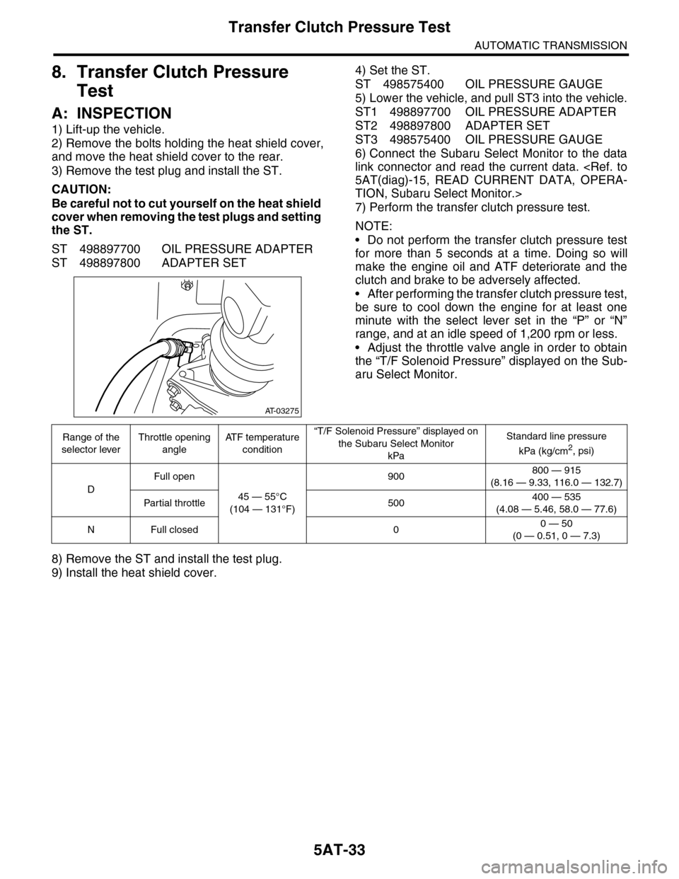
3) Remove the test plug and install the ST.
CAUTION:
Be careful not to cut yourself on the heat shield
cover when removing the test plugs and setting
the ST.
ST 498897700 OIL PRESSURE ADAPTER
ST 498897800 ADAPTER SET
4) Set the ST.
ST 498575400 OIL PRESSURE GAUGE
5) Lower the vehicle, and pull ST3 into the vehicle.
ST1 498897700 OIL PRESSURE ADAPTER
ST2 498897800 ADAPTER SET
ST3 498575400 OIL PRESSURE GAUGE
6) Connect the Subaru Select Monitor to the data
link connector and read the current data.
5AT(diag)-15, READ CURRENT DATA, OPERA-
TION, Subaru Select Monitor.>
7) Perform the transfer clutch pressure test.
NOTE:
•Do not perform the transfer clutch pressure test
for more than 5 seconds at a time. Doing so will
make the engine oil and ATF deteriorate and the
clutch and brake to be adversely affected.
•After performing the transfer clutch pressure test,
be sure to cool down the engine for at least one
minute with the select lever set in the “P” or “N”
range, and at an idle speed of 1,200 rpm or less.
•Adjust the throttle valve angle in order to obtain
the “T/F Solenoid Pressure” displayed on the Sub-
aru Select Monitor.
8) Remove the ST and install the test plug.
9) Install the heat shield cover.
AT-03275
Range of the
selector lever
Throttle opening
angle
AT F t e m p e r a t u r e
condition
“T/F Solenoid Pressure” displayed on
the Subaru Select Monitor
kPa
Standard line pressure
kPa (kg/cm2, psi)
D
Full open
45 — 55°C
(104 — 131°F)
900800 — 915
(8.16 — 9.33, 116.0 — 132.7)
Par tial throttle 500400 — 535
(4.08 — 5.46, 58.0 — 77.6)
NFull closed 00 — 50
(0 — 0.51, 0 — 7.3)
Page 2050 of 2453
5AT-34
Automatic Transmission Assembly
AUTOMATIC TRANSMISSION
9. Automatic Transmission As-
sembly
A: REMOVAL
1) Set the vehicle on a lift.
2) Open the front hood and support with the hood
stay.
3) Disconnect the ground cable from battery.
4) Remove the collector cover.
5) Remove the air intake chamber.
IN(H6DO)-6, REMOVAL, Air Intake Chamber.>
6) Remove the air breather hose.
REMOVAL, Air Breather Hose.>
7) Remove the starter.
MOVAL, Starter.>
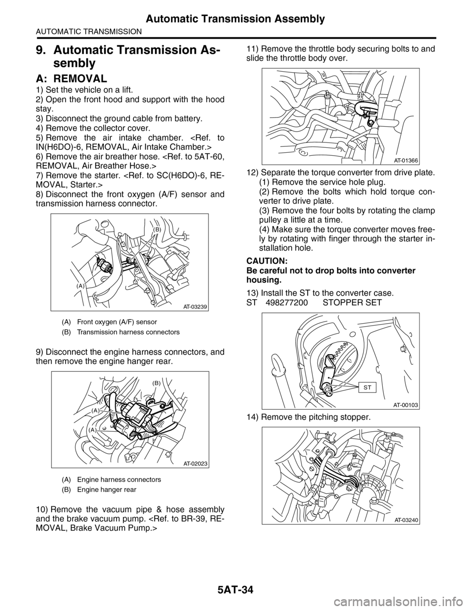
8) Disconnect the front oxygen (A/F) sensor and
transmission harness connector.
9) Disconnect the engine harness connectors, and
then remove the engine hanger rear.
10) Remove the vacuum pipe & hose assembly
and the brake vacuum pump.
MOVAL, Brake Vacuum Pump.>
11) Remove the throttle body securing bolts to and
slide the throttle body over.
12) Separate the torque converter from drive plate.
(1) Remove the service hole plug.
(2) Remove the bolts which hold torque con-
verter to drive plate.
(3) Remove the four bolts by rotating the clamp
pulley a little at a time.
(4) Make sure the torque converter moves free-
ly by rotating with finger through the starter in-
stallation hole.
CAUTION:
Be careful not to drop bolts into converter
housing.
13) Install the ST to the converter case.
ST 498277200 STOPPER SET
14) Remove the pitching stopper.
(A) Front oxygen (A/F) sensor
(B) Transmission harness connectors
(A) Engine harness connectors
(B) Engine hanger rear
(A)
(B)
AT-03239
(B)
(A)
(A)
AT-02023
AT-01366
AT-00103
ST
AT-03240
Page 2051 of 2453
5AT-35
Automatic Transmission Assembly
AUTOMATIC TRANSMISSION
15) Remove the pitching stopper bracket.
16) Set the ST.
ST1 41099AA010 ENGINE SUPPORT BRACK-
ET
ST2 41099AA020 ENGINE SUPPORT
17) Remove the transmission mounting bolt (upper
side).
18) Lift-up the vehicle.
19) Remove the under cover.
20) Remove the front exhaust pipe, rear exhaust
pipe and muffler.
AL, Front Exhaust Pipe.>
REMOVAL, Rear Exhaust Pipe.>
EX(H6DO)-8, REMOVAL, Muffler.>
21) Remove the heat shield cover.
22) Remove the ATF drain plug to drain ATF.
23) Remove the oil charge pipe.
24) Disconnect the connector from turbine speed
sensor 1.
AT-03241
AT-03242
ST2
ST1
AT-03237
(A) Oil pan
(B) Drain plug
AT-03243
(A)
AT-01361
(B)
AT-01371
AT-01642
Page 2053 of 2453
5AT-37
Automatic Transmission Assembly
AUTOMATIC TRANSMISSION
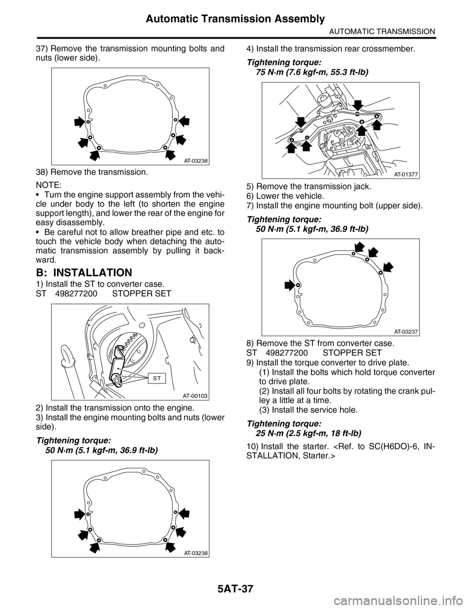
37) Remove the transmission mounting bolts and
nuts (lower side).
38) Remove the transmission.
NOTE:
•Turn the engine support assembly from the vehi-
cle under body to the left (to shorten the engine
support length), and lower the rear of the engine for
easy disassembly.
•Be careful not to allow breather pipe and etc. to
touch the vehicle body when detaching the auto-
matic transmission assembly by pulling it back-
ward.
B: INSTALLATION
1) Install the ST to converter case.
ST 498277200 STOPPER SET
2) Install the transmission onto the engine.
3) Install the engine mounting bolts and nuts (lower
side).
Tightening torque:
50 N·m (5.1 kgf-m, 36.9 ft-lb)
4) Install the transmission rear crossmember.
Tightening torque:
75 N·m (7.6 kgf-m, 55.3 ft-lb)
5) Remove the transmission jack.
6) Lower the vehicle.
7) Install the engine mounting bolt (upper side).
Tightening torque:
50 N·m (5.1 kgf-m, 36.9 ft-lb)
8) Remove the ST from converter case.
ST 498277200 STOPPER SET
9) Install the torque converter to drive plate.
(1) Install the bolts which hold torque converter
to drive plate.
(2) Install all four bolts by rotating the crank pul-
ley a little at a time.
(3) Install the service hole.
Tightening torque:
25 N·m (2.5 kgf-m, 18 ft-lb)
10) Install the starter.
STALLATION, Starter.>
AT-03238
AT-00103
ST
AT-03238
AT-01377
AT-03237
Page 2056 of 2453
5AT-40
Automatic Transmission Assembly
AUTOMATIC TRANSMISSION
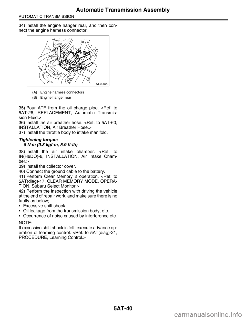
34) Install the engine hanger rear, and then con-
nect the engine harness connector.
35) Pour ATF from the oil charge pipe.
5AT-26, REPLACEMENT, Automatic Transmis-
sion Fluid.>
36) Install the air breather hose.
INSTALLATION, Air Breather Hose.>
37) Install the throttle body to intake manifold.
Tightening torque:
8 N·m (0.8 kgf-m, 5.9 ft-lb)
38) Install the air intake chamber.
IN(H6DO)-6, INSTALLATION, Air Intake Cham-
ber.>
39) Install the collector cover.
40) Connect the ground cable to the battery.
41) Perform Clear Memory 2 operation.
5AT(diag)-17, CLEAR MEMORY MODE, OPERA-
TION, Subaru Select Monitor.>
42) Perform the inspection with driving the vehicle
at the end of repair work, and make sure there is no
faulty as below;
•Excessive shift shock
•Oil leakage from the transmission body, etc.
•Occurrence of noise caused by interference etc.
NOTE:
If excessive shift shock is felt, execute advance op-
eration of learning control.
PROCEDURE, Learning Control.>
(A) Engine harness connectors
(B) Engine hanger rear
(B)
(A)
(A)
AT-02023
Page 2123 of 2453
5AT(diag)-6
General Description
AUTOMATIC TRANSMISSION (DIAGNOSTICS)
5. OPERATION OF SHIFT SELECT LEVER
Make sure there is no noise, dragging or contact
pattern in each select lever range.
WARNING:
Stop the engine while checking operation of the
select lever.
C: PREPARATION TOOL
1. SPECIAL TOOL
2. GENERAL TOOL
AT-03277
ILLUSTRATION TOOL NUMBER DESCRIPTION REMARKS
18482AA010 CARTRIDGE Troubleshooting for electrical system.
22771AA030 SUBARU SELECT
MONITOR KIT
Tr o u b l e s h o o t i n g f o r e l e c t r i c a l s y s t e m .
TOOL NAME REMARKS
Circuit tester Used for measuring resistance, voltage and current.
Oscilloscope Used for measuring sensor.
ST18482AA010
ST22771AA030
Page 2124 of 2453
5AT(diag)-7
Electrical Component Location
AUTOMATIC TRANSMISSION (DIAGNOSTICS)
4. Electrical Component Location
A: LOCATION
1. CONTROL MODULE
(1) Engine control module (ECM) (3) Transmission control module
(TCM)
(4) Data link connector
(2) SPORT indicator light (AT warning
light)
(5) Body integrated unit
AT-03278
(1)
(3)(4) (2) (5)
EN-03680
(1)
AT-03279(2)
(3)
(5)
AT-03296EN-03683
(4)