2009 SUBARU TRIBECA engine
[x] Cancel search: enginePage 1956 of 2453
ME(H6DO)-90
Engine Noise
MECHANICAL
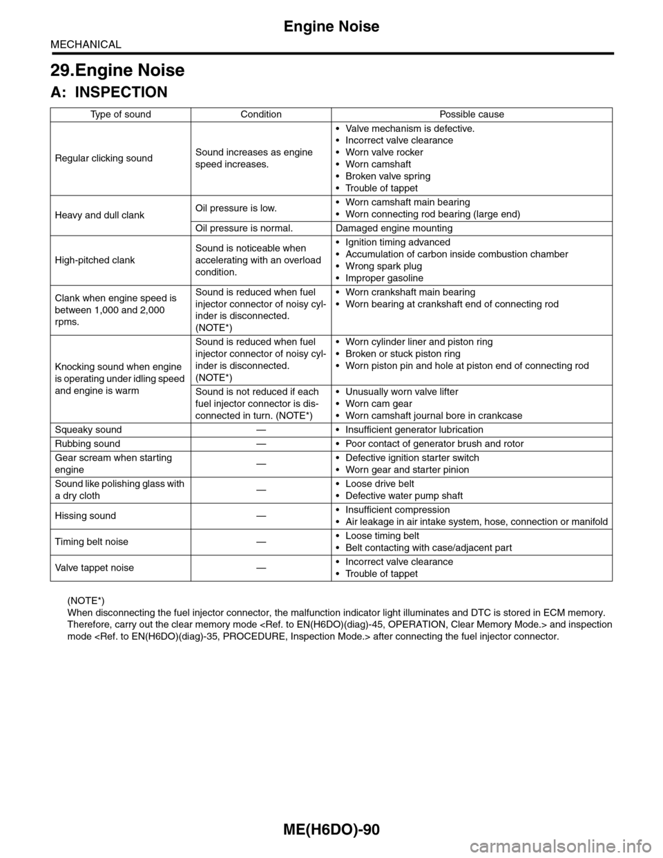
29.Engine Noise
A: INSPECTION
(NOTE*)
When disconnecting the fuel injector connector, the malfunction indicator light illuminates and DTC is stored in ECM memory.
Therefore, carry out the clear memory mode
mode
Ty p e o f s o u n d C o n d i t i o n P o s s i b l e c a u s e
Regular clicking soundSound increases as engine
speed increases.
•Valve mechanism is defective.
•Incorrect valve clearance
•Worn valve rocker
•Worn camshaft
•Broken valve spring
•Trouble of tappet
Heavy and dull clankOil pressure is low.•Worn camshaft main bearing
•Worn connecting rod bearing (large end)
Oil pressure is normal. Damaged engine mounting
High-pitched clank
Sound is noticeable when
accelerating with an overload
condition.
•Ignition timing advanced
•Accumulation of carbon inside combustion chamber
•Wrong spark plug
•Improper gasoline
Clank when engine speed is
between 1,000 and 2,000
rpms.
Sound is reduced when fuel
injector connector of noisy cyl-
inder is disconnected.
(NOTE*)
•Worn crankshaft main bearing
•Worn bearing at crankshaft end of connecting rod
Knocking sound when engine
is operating under idling speed
and engine is warm
Sound is reduced when fuel
injector connector of noisy cyl-
inder is disconnected.
(NOTE*)
•Worn cylinder liner and piston ring
•Broken or stuck piston ring
•Worn piston pin and hole at piston end of connecting rod
Sound is not reduced if each
fuel injector connector is dis-
connected in turn. (NOTE*)
•Unusually worn valve lifter
•Worn cam gear
•Worn camshaft journal bore in crankcase
Squeaky sound — • Insufficient generator lubrication
Rubbing sound — • Poor contact of generator brush and rotor
Gear scream when starting
engine—•Defective ignition starter switch
•Worn gear and starter pinion
Sound like polishing glass with
a dry cloth—•Loose drive belt
•Defective water pump shaft
Hissing sound —•Insufficient compression
•Air leakage in air intake system, hose, connection or manifold
Timing belt noise —•Loose timing belt
•Belt contacting with case/adjacent part
Va l ve t a p p e t n o i s e —•Incorrect valve clearance
•Trouble of tappet
Page 1976 of 2453
SC(H6DO)-18
Starter
STARTING/CHARGING SYSTEMS
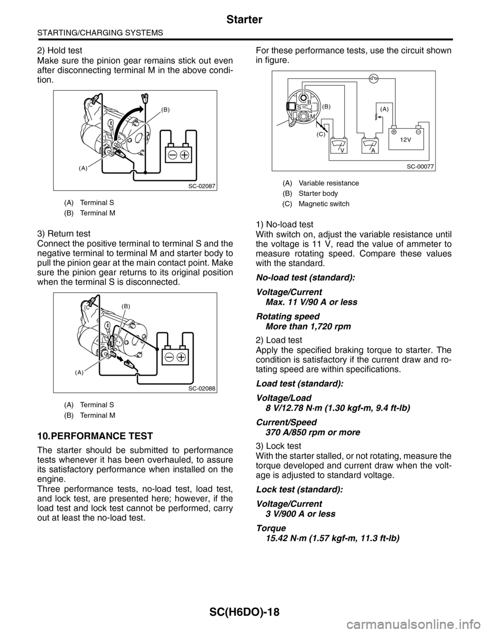
2) Hold test
Make sure the pinion gear remains stick out even
after disconnecting terminal M in the above condi-
tion.
3) Return test
Connect the positive terminal to terminal S and the
negative terminal to terminal M and starter body to
pull the pinion gear at the main contact point. Make
sure the pinion gear returns to its original position
when the terminal S is disconnected.
10.PERFORMANCE TEST
The starter should be submitted to performance
tests whenever it has been overhauled, to assure
its satisfactory performance when installed on the
engine.
Three performance tests, no-load test, load test,
and lock test, are presented here; however, if the
load test and lock test cannot be performed, carry
out at least the no-load test.
For these performance tests, use the circuit shown
in figure.
1) No-load test
With switch on, adjust the variable resistance until
the voltage is 11 V, read the value of ammeter to
measure rotating speed. Compare these values
with the standard.
No-load test (standard):
Voltage/Current
Max. 11 V/90 A or less
Rotating speed
More than 1,720 rpm
2) Load test
Apply the specified braking torque to starter. The
condition is satisfactory if the current draw and ro-
tating speed are within specifications.
Load test (standard):
Voltage/Load
8 V/12.78 N·m (1.30 kgf-m, 9.4 ft-lb)
Current/Speed
370 A/850 rpm or more
3) Lock test
With the starter stalled, or not rotating, measure the
torque developed and current draw when the volt-
age is adjusted to standard voltage.
Lock test (standard):
Voltage/Current
3 V/900 A or less
Torque
15.42 N·m (1.57 kgf-m, 11.3 ft-lb)
(A) Terminal S
(B) Terminal M
(A) Terminal S
(B) Terminal M
SC-02087
(B)
(A)
SC-02088
(A)
(B)
(A) Variable resistance
(B) Starter body
(C) Magnetic switch
SC-00077
(A)(B)
(C)12V
+
AV
BS
M
Page 1983 of 2453
SC(H6DO)-25
Battery
STARTING/CHARGING SYSTEMS
4. Battery
A: REMOVAL
1) Disconnect the positive (+) terminal after discon-
necting the negative (–) terminal of battery.
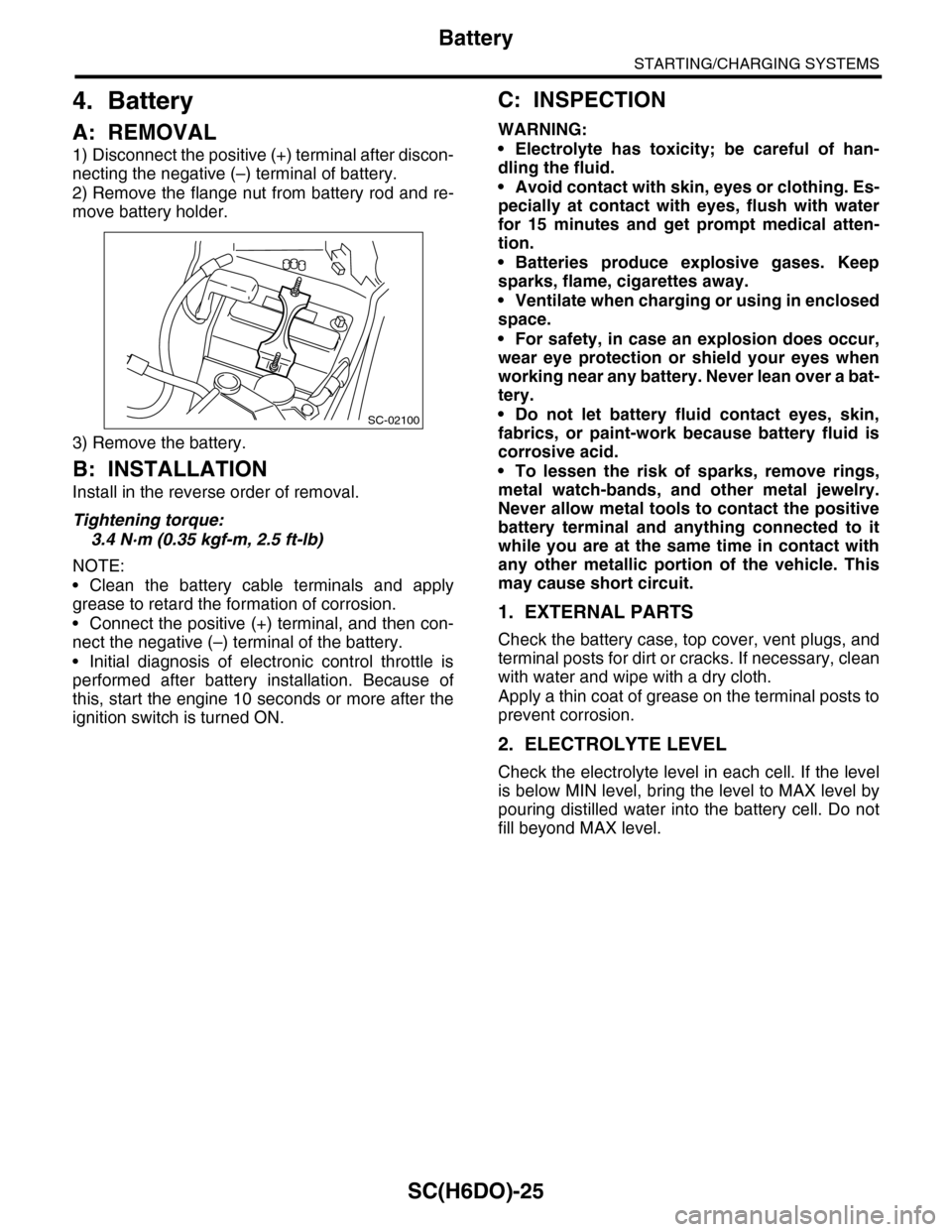
2) Remove the flange nut from battery rod and re-
move battery holder.
3) Remove the battery.
B: INSTALLATION
Install in the reverse order of removal.
Tightening torque:
3.4 N·m (0.35 kgf-m, 2.5 ft-lb)
NOTE:
•Clean the battery cable terminals and apply
grease to retard the formation of corrosion.
•Connect the positive (+) terminal, and then con-
nect the negative (–) terminal of the battery.
•Initial diagnosis of electronic control throttle is
performed after battery installation. Because of
this, start the engine 10 seconds or more after the
ignition switch is turned ON.
C: INSPECTION
WARNING:
•Electrolyte has toxicity; be careful of han-
dling the fluid.
•Avoid contact with skin, eyes or clothing. Es-
pecially at contact with eyes, flush with water
for 15 minutes and get prompt medical atten-
tion.
•Batteries produce explosive gases. Keep
sparks, flame, cigarettes away.
•Ventilate when charging or using in enclosed
space.
•For safety, in case an explosion does occur,
wear eye protection or shield your eyes when
working near any battery. Never lean over a bat-
tery.
•Do not let battery fluid contact eyes, skin,
fabrics, or paint-work because battery fluid is
corrosive acid.
•To lessen the risk of sparks, remove rings,
metal watch-bands, and other metal jewelry.
Never allow metal tools to contact the positive
battery terminal and anything connected to it
while you are at the same time in contact with
any other metallic portion of the vehicle. This
may cause short circuit.
1. EXTERNAL PARTS
Check the battery case, top cover, vent plugs, and
terminal posts for dirt or cracks. If necessary, clean
with water and wipe with a dry cloth.
Apply a thin coat of grease on the terminal posts to
prevent corrosion.
2. ELECTROLYTE LEVEL
Check the electrolyte level in each cell. If the level
is below MIN level, bring the level to MAX level by
pouring distilled water into the battery cell. Do not
fill beyond MAX level.
SC-02100
Page 1986 of 2453
PM-3
Schedule
PERIODIC MAINTENANCE SERVICES
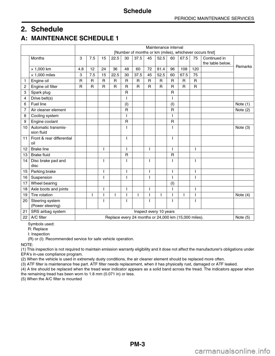
2. Schedule
A: MAINTENANCE SCHEDULE 1
Symbols used:
R: Replace
I: Inspection
(R) or (I): Recommended service for safe vehicle operation.
NOTE:(1) This inspection is not required to maintain emission warranty eligibility and it dose not affect the manufacturer's obligations under
EPA's in-use compliance program.
(2) When the vehicle is used in extremely dusty conditions, the air cleaner element should be replaced more often.
(3) ATF filter is maintenance free part. ATF filter needs replacement, when it has physically rust, damaged or ATF leaked.
(4) A tire should be replaced when the tread wear indicator appears as a solid band across the tread. The indicators appear when
the remaining tread has been worn to 1.8 mm (0.071 in) or less.
(5) When the A/C filter is mounted
Maintenance interval
[Number of months or km (miles), whichever occurs first]
Months 3 7.51522.53037.54552.56067.575Continued in
the table below.Remarks× 1,000 km 4.8 12 24 36 48 60 72 81.4 96 108 120
× 1,000 miles 3 7.5 15 22.5 30 37.5 45 52.5 60 67.5 75
1Engine oil R R R R R R R R R R R
2Engine oil filter R R R R R R R R R R R
3Spark plug R R
4Drive belt(s) I I
6Fuel line (I) (I) Note (1)
7Air cleaner element R R Note (2)
8Cooling system I I
9Engine coolant R R
10 Automatic transmis-
sion fluid
I I Note (3)
11 Front & rear differential
oil
I I
12 Brake line I I I I I
13 Brake fluid R R
14 Disc brake pad and
disc
I I I I I
15 Parking brake I I I I I
16 Suspension I I I I I
17 Wheel bearing (I)
18 Axle boots and joints I I I I I
19 Tire rotation I I I I I I I I I I Note (4)
20 Steering system
(Power steering)
I I I I I
21 SRS airbag system Inspect every 10 years
22 A/C filter Replace every 24 months or 24,000 km (15,000 miles). Note (5)
Page 1987 of 2453
PM-4
Schedule
PERIODIC MAINTENANCE SERVICES
Symbols used:
R: Replace
I: Inspection
(R) or (I): Recommended service for safe vehicle operation.
NOTE:(1) This inspection is not required to maintain emission warranty eligibility and it dose not affect the manufacturer's obligations under
EPA's in-use compliance program.
(2) When the vehicle is used in extremely dusty conditions, the air cleaner element should be replaced more often.
(3) ATF filter is maintenance free part. ATF filter needs replacement, when it has physically rust, damaged or ATF leaked.
(4) A tire should be replaced when the tread wear indicator appears as a solid band across the tread. The indicators appear when
the remaining tread has been worn to 1.8 mm (0.071 in) or less.
(5) When the A/C filter is mounted
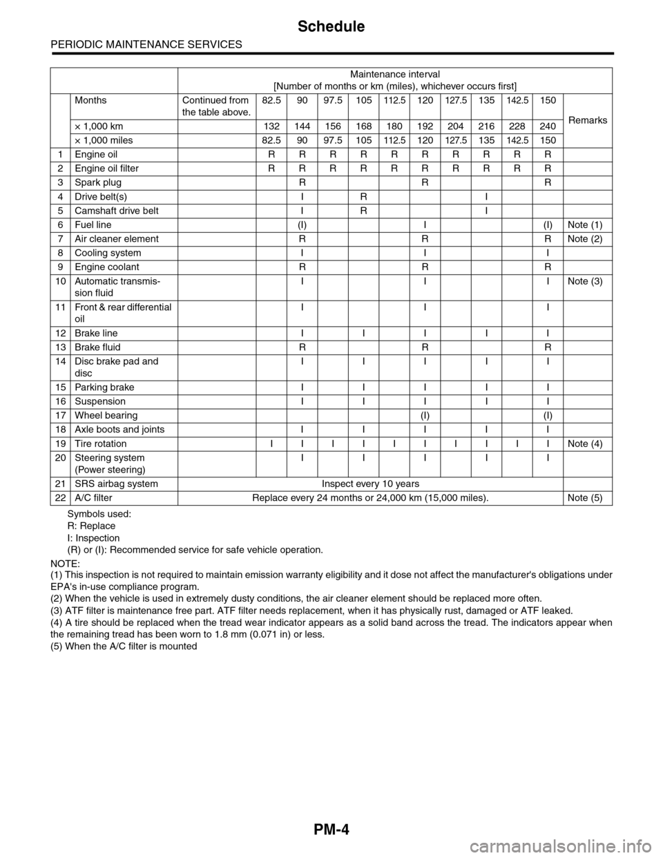
Maintenance interval
[Number of months or km (miles), whichever occurs first]
Months Continued from
the table above.
82.5 90 97.5 105112.5120127.5135142.5150
Remarks× 1,000 km 132 144 156 168 180 192 204 216 228 240
× 1,000 miles 82.5 90 97.5 105112.5120127.5135142.5150
1Engine oil R R R R R R R R R R
2Engine oil filter R R R R R R R R R R
3Spark plug R R R
4Drive belt(s) I R I
5Camshaft drive belt I R I
6Fuel line (I) I (I) Note (1)
7Air cleaner element R R R Note (2)
8Cooling system I I I
9Engine coolant R R R
10 Automatic transmis-
sion fluid
I I INote (3)
11 Front & rear differential
oil
I I I
12 Brake line I I I I I
13 Brake fluid R R R
14 Disc brake pad and
disc
I I I I I
15 Parking brake I I I I I
16 Suspension I I I I I
17 Wheel bearing (I) (I)
18 Axle boots and joints I I I I I
19 Tire rotation I I I I I I I I I I Note (4)
20 Steering system
(Power steering)
I I I I I
21 SRS airbag system Inspect every 10 years
22 A/C filter Replace every 24 months or 24,000 km (15,000 miles). Note (5)
Page 1988 of 2453
PM-5
Schedule
PERIODIC MAINTENANCE SERVICES
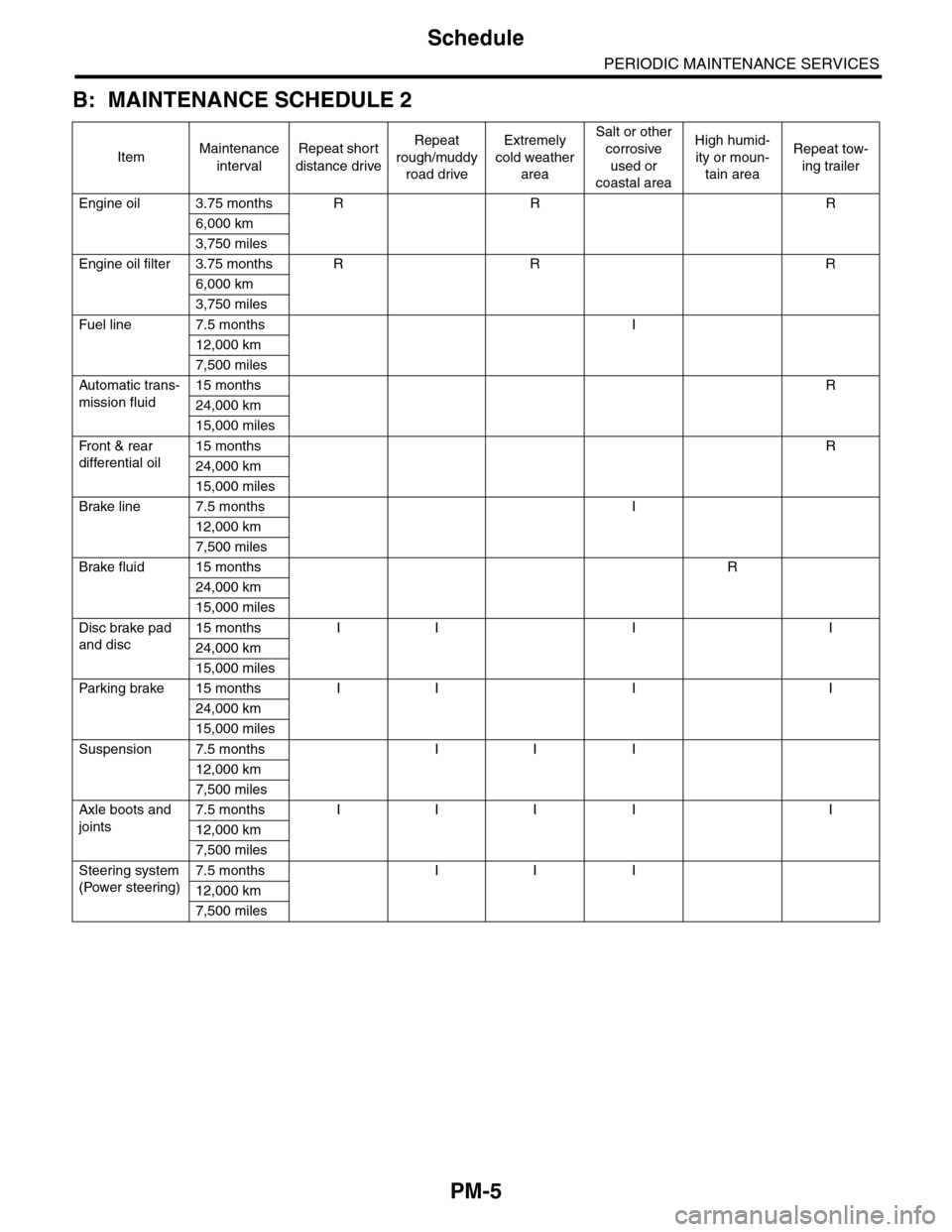
B: MAINTENANCE SCHEDULE 2
ItemMaintenance
interval
Repeat short
distance drive
Repeat
rough/muddy
road drive
Extremely
cold weather
area
Salt or other
corrosive
used or
coastal area
High humid-
ity or moun-
tain area
Repeat tow-
ing trailer
Engine oil 3.75 months R R R
6,000 km
3,750 miles
Engine oil filter 3.75 months R R R
6,000 km
3,750 miles
Fuel line 7.5 months I
12,000 km
7,500 miles
Automatic trans-
mission fluid
15 months R
24,000 km
15,000 miles
Fr o nt & r ea r
differential oil
15 months R
24,000 km
15,000 miles
Brake line 7.5 months I
12,000 km
7,500 miles
Brake fluid 15 months R
24,000 km
15,000 miles
Disc brake pad
and disc
15 months I I I I
24,000 km
15,000 miles
Par king brake 15 months I I I I
24,000 km
15,000 miles
Suspension 7.5 months I I I
12,000 km
7,500 miles
Axle boots and
joints
7.5 months I I I I I
12,000 km
7,500 miles
Steering system
(Power steering)
7.5 months I I I
12,000 km
7,500 miles
Page 1989 of 2453
PM-6
Engine Oil
PERIODIC MAINTENANCE SERVICES
3. Engine Oil
A: REPLACEMENT
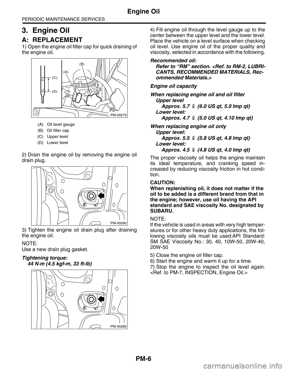
1) Open the engine oil filter cap for quick draining of
the engine oil.
2) Drain the engine oil by removing the engine oil
drain plug.
3) Tighten the engine oil drain plug after draining
the engine oil.
NOTE:
Use a new drain plug gasket.
Tightening torque:
44 N·m (4.5 kgf-m, 33 ft-lb)
4) Fill engine oil through the level gauge up to the
center between the upper level and the lower level.
Place the vehicle on a level surface when checking
oil level. Use engine oil of the proper quality and
viscosity, selected in accordance with the following.
Recommended oil:
Refer to “RM” section.
ommended Materials.>
Engine oil capacity
When replacing engine oil and oil filter
Upper level
Approx. 5.7 2 (6.0 US qt, 5.0 Imp qt)
Lower level:
Approx. 4.7 2 (5.0 US qt, 4.10 Imp qt)
When replacing engine oil only
Upper level:
Approx. 5.5 2 (5.8 US qt, 4.8 Imp qt)
Lower level:
Approx. 4.5 2 (4.8 US qt, 4.0 Imp qt)
The proper viscosity oil helps the engine maintain
its ideal temperature, and cranking speed in-
creased by reducing viscosity friction in hot condi-
tion.
CAUTION:
When replenishing oil, it does not matter if the
oil to be added is a different brand from that in
the engine; however, use oil having the API
standard and SAE viscosity No. designated by
SUBARU.
NOTE:
If the vehicle is used in areas with very high temper-
atures or for other heavy duty applications, the fol-
lowing viscosity oils must be used:API Standard:
SM SAE Viscosity No.: 30, 40, 10W-50, 20W-40,
20W-50
5) Close the engine oil filler cap.
6) Start the engine and warm it up for a time.
7) Stop the engine to inspect the oil level again.
(A) Oil level gauge
(B) Oil filler cap
(C) Upper level
(D) Lower level
PM-00279
(A)
(B)
(C)
(D)
PM-00280
PM-00280
Page 1990 of 2453
PM-7
Engine Oil
PERIODIC MAINTENANCE SERVICES
B: INSPECTION
1) Park the vehicle on a level surface.
2) Remove the oil level gauge and wipe it clean.
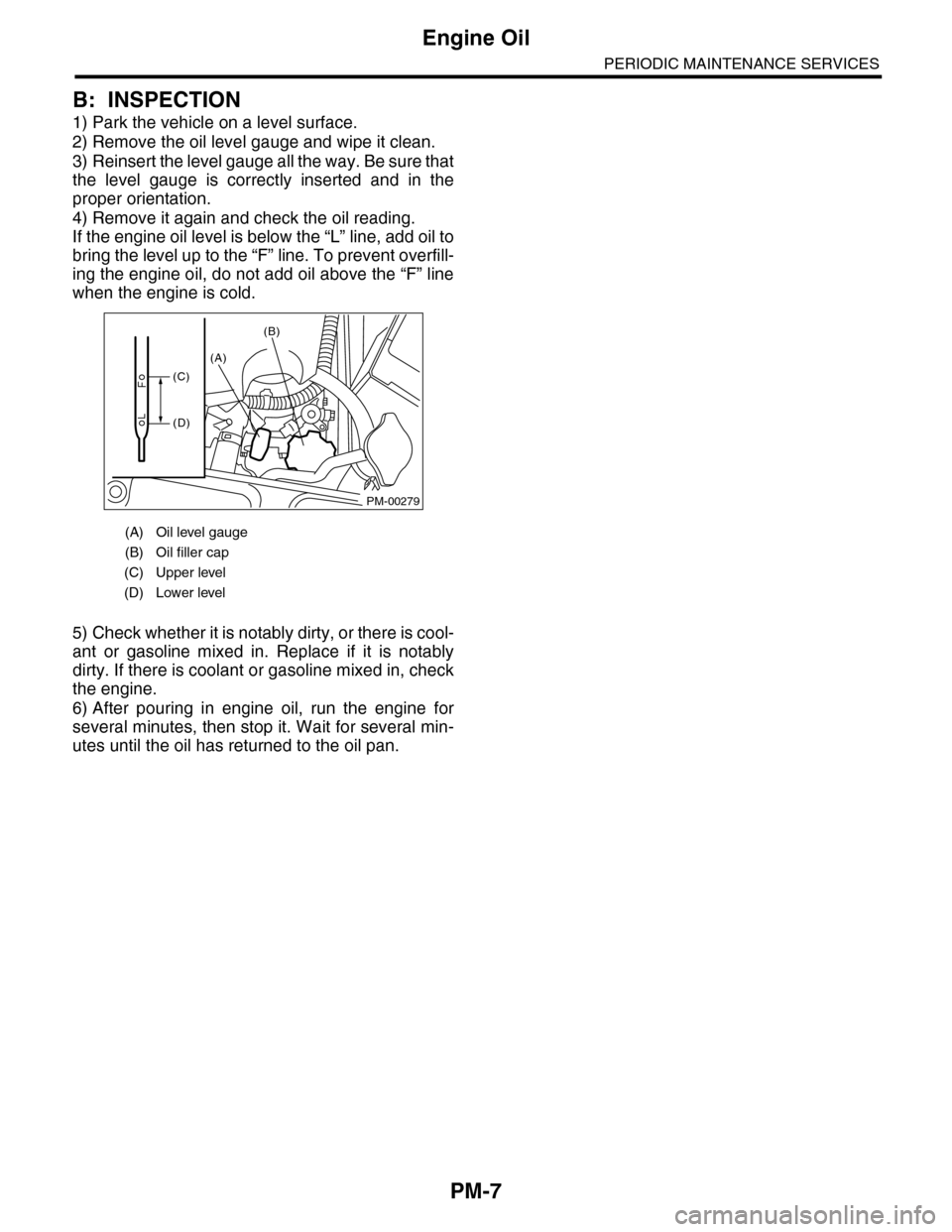
3) Reinsert the level gauge all the way. Be sure that
the level gauge is correctly inserted and in the
proper orientation.
4) Remove it again and check the oil reading.
If the engine oil level is below the “L” line, add oil to
bring the level up to the “F” line. To prevent overfill-
ing the engine oil, do not add oil above the “F” line
when the engine is cold.
5) Check whether it is notably dirty, or there is cool-
ant or gasoline mixed in. Replace if it is notably
dirty. If there is coolant or gasoline mixed in, check
the engine.
6) After pouring in engine oil, run the engine for
several minutes, then stop it. Wait for several min-
utes until the oil has returned to the oil pan.
(A) Oil level gauge
(B) Oil filler cap
(C) Upper level
(D) Lower level
PM-00279
(A)
(B)
(C)
(D)