Page 1383 of 2453
EN(H6DO)(diag)-222
Diagnostic Procedure with Diagnostic Trouble Code (DTC)
ENGINE (DIAGNOSTICS)
BF:DTC P0182 FUEL TEMPERATURE SENSOR “A” CIRCUIT LOW INPUT
DTC DETECTING CONDITION:
•Immediately at fault recognition
•GENERAL DESCRIPTION
CIRCUIT LOW INPUT, Diagnostic Trouble Code (DTC) Detecting Criteria.>
CAUTION:
After repair or replacement of faulty parts, perform Clear Memory Mode
OPERATION, Clear Memory Mode.> and Inspection Mode
Inspection Mode.>.
WIRING DIAGRAM:
EN-03740
B424
3017
ECMB135
R58
R60
R15
R1
B98
23
FUEL TEMPERATURESENSOR
FUEL TANK
R58
123456
B424
34561278
: TERMINAL NO. OPTIONAL ARRANGEMENT*
**
R233
**
12
1620
R60
12
10115634897131412
1234
R233B98
3412 8910 1112 13 14 15 16 17 18 19 20 21 22 23 2456 7
B135
5672134
29
101112131415252416
30
98171819202821222332312627333435
Page 1384 of 2453

EN(H6DO)(diag)-223
Diagnostic Procedure with Diagnostic Trouble Code (DTC)
ENGINE (DIAGNOSTICS)
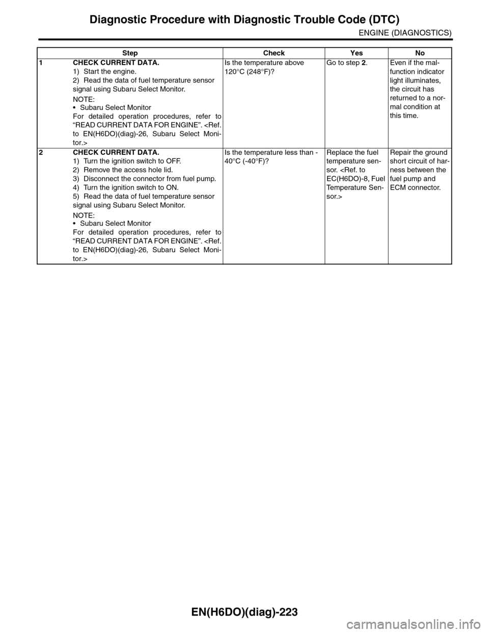
Step Check Yes No
1CHECK CURRENT DATA.
1) Start the engine.
2) Read the data of fuel temperature sensor
signal using Subaru Select Monitor.
NOTE:•Subaru Select Monitor
For detailed operation procedures, refer to
“READ CURRENT DATA FOR ENGINE”.
to EN(H6DO)(diag)-26, Subaru Select Moni-
tor.>
Is the temperature above
120°C (248°F)?
Go to step 2.Even if the mal-
function indicator
light illuminates,
the circuit has
returned to a nor-
mal condition at
this time.
2CHECK CURRENT DATA.
1) Turn the ignition switch to OFF.
2) Remove the access hole lid.
3) Disconnect the connector from fuel pump.
4) Turn the ignition switch to ON.
5) Read the data of fuel temperature sensor
signal using Subaru Select Monitor.
NOTE:•Subaru Select Monitor
For detailed operation procedures, refer to
“READ CURRENT DATA FOR ENGINE”.
to EN(H6DO)(diag)-26, Subaru Select Moni-
tor.>
Is the temperature less than -
40°C (-40°F)?
Replace the fuel
temperature sen-
sor.
EC(H6DO)-8, Fuel
Te m p e r a t u r e S e n -
sor.>
Repair the ground
short circuit of har-
ness between the
fuel pump and
ECM connector.
Page 1385 of 2453
EN(H6DO)(diag)-224
Diagnostic Procedure with Diagnostic Trouble Code (DTC)
ENGINE (DIAGNOSTICS)
BG:DTC P0183 FUEL TEMPERATURE SENSOR “A” CIRCUIT HIGH INPUT
DTC DETECTING CONDITION:
•Immediately at fault recognition
•GENERAL DESCRIPTION
CIRCUIT HIGH INPUT, Diagnostic Trouble Code (DTC) Detecting Criteria.>
CAUTION:
After repair or replacement of faulty parts, perform Clear Memory Mode
OPERATION, Clear Memory Mode.> and Inspection Mode
Inspection Mode.>.
WIRING DIAGRAM:
EN-03740
B424
3017
ECMB135
R58
R60
R15
R1
B98
23
FUEL TEMPERATURESENSOR
FUEL TANK
R58
123456
B424
34561278
: TERMINAL NO. OPTIONAL ARRANGEMENT*
**
R233
**
12
1620
R60
12
10115634897131412
1234
R233B98
3412 8910 1112 13 14 15 16 17 18 19 20 21 22 23 2456 7
B135
5672134
29
101112131415252416
30
98171819202821222332312627333435
Page 1386 of 2453

EN(H6DO)(diag)-225
Diagnostic Procedure with Diagnostic Trouble Code (DTC)
ENGINE (DIAGNOSTICS)
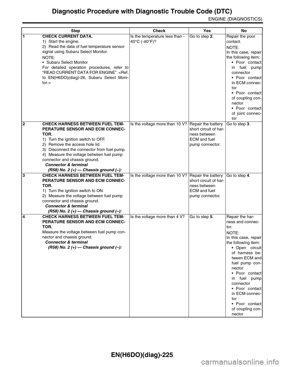
Step Check Yes No
1CHECK CURRENT DATA.
1) Start the engine.
2) Read the data of fuel temperature sensor
signal using Subaru Select Monitor.
NOTE:•Subaru Select Monitor
For detailed operation procedures, refer to
“READ CURRENT DATA FOR ENGINE”.
to EN(H6DO)(diag)-26, Subaru Select Moni-
tor.>
Is the temperature less than -
40°C (-40°F)?
Go to step 2.Repair the poor
contact.
NOTE:
In this case, repair
the following item:
•Poor contact
in fuel pump
connector
•Poor contact
in ECM connec-
tor
•Poor contact
of coupling con-
nector
•Poor contact
of joint connec-
tor
2 CHECK HARNESS BETWEEN FUEL TEM-
PERATURE SENSOR AND ECM CONNEC-
TOR.
1) Turn the ignition switch to OFF.
2) Remove the access hole lid.
3) Disconnect the connector from fuel pump.
4) Measure the voltage between fuel pump
connector and chassis ground.
Connector & terminal
(R58) No. 2 (+) — Chassis ground (–):
Is the voltage more than 10 V? Repair the battery
short circuit of har-
ness between
ECM and fuel
pump connector.
Go to step 3.
3 CHECK HARNESS BETWEEN FUEL TEM-
PERATURE SENSOR AND ECM CONNEC-
TOR.
1) Turn the ignition switch to ON.
2) Measure the voltage between fuel pump
connector and chassis ground.
Connector & terminal
(R58) No. 2 (+) — Chassis ground (–):
Is the voltage more than 10 V? Repair the battery
short circuit of har-
ness between
ECM and fuel
pump connector.
Go to step 4.
4 CHECK HARNESS BETWEEN FUEL TEM-
PERATURE SENSOR AND ECM CONNEC-
TOR.
Measure the voltage between fuel pump con-
nector and chassis ground.
Connector & terminal
(R58) No. 2 (+) — Chassis ground (–):
Is the voltage more than 4 V? Go to step 5.Repair the har-
ness and connec-
tor.
NOTE:In this case, repair
the following item:
•Open circuit
of harness be-
tween ECM and
fuel pump con-
nector
•Poor contact
in fuel pump
connector
•Poor contact
in ECM connec-
tor
•Poor contact
of coupling con-
nector
Page 1387 of 2453
EN(H6DO)(diag)-226
Diagnostic Procedure with Diagnostic Trouble Code (DTC)
ENGINE (DIAGNOSTICS)
5 CHECK HARNESS BETWEEN FUEL TEM-
PERATURE SENSOR AND ECM CONNEC-
TOR.
1) Turn the ignition switch to OFF.
2) Disconnect the connectors from ECM.
3) Measure the resistance of harness
between fuel pump connector and ECM.
Connector & terminal
(R58) No. 3 — (B135) No. 30:
Is the resistance less than 1
Ω?
Replace the fuel
temperature sen-
sor.
EC(H6DO)-8, Fuel
Te m p e r a t u r e S e n -
sor.>
Repair the har-
ness and connec-
tor.
NOTE:In this case, repair
the following item:
•Open circuit
of harness be-
tween ECM and
fuel pump con-
nector
•Poor contact
in fuel pump
connector
•Poor contact
in ECM connec-
tor
•Poor contact
of coupling con-
nector
•Poor contact
of joint connec-
tor
Step Check Yes No
Page 1401 of 2453
EN(H6DO)(diag)-240
Diagnostic Procedure with Diagnostic Trouble Code (DTC)
ENGINE (DIAGNOSTICS)
BM:DTC P0230 FUEL PUMP PRIMARY CIRCUIT
DTC DETECTING CONDITION:
•Detected when two consecutive driving cycles with fault occur.
•GENERAL DESCRIPTION
agnostic Trouble Code (DTC) Detecting Criteria.>
CAUTION:
After repair or replacement of faulty parts, perform Clear Memory Mode
OPERATION, Clear Memory Mode.> and Inspection Mode
Inspection Mode.>.
WIRING DIAGRAM:
EN-03653
EE
M
10
76
56
NO.11
B362
R122
B135B:
B136C:
R58
7
B33C12
21
985
FUEL PUMPCONTROL UNIT
FUELPUMPECM
BATTERY
FUEL PUMPRELAY
B362
5678
3412
R1
B98218
23B98
R1
R15
R60712
R58
2
546
13
B135B:
567821943102422 23 2511 12 13 14 1526 2728
16 17 18 1920 2129 30 31 32 33 34 35
R122
34125891067
B98
123456 78910 1112 13 16 1714 15 18 19 2021222324
R60
12
10115634897131412
B136
16101112131415252430
9871718192028212223293231
123456
2726333435
C:
Page 1402 of 2453

EN(H6DO)(diag)-241
Diagnostic Procedure with Diagnostic Trouble Code (DTC)
ENGINE (DIAGNOSTICS)
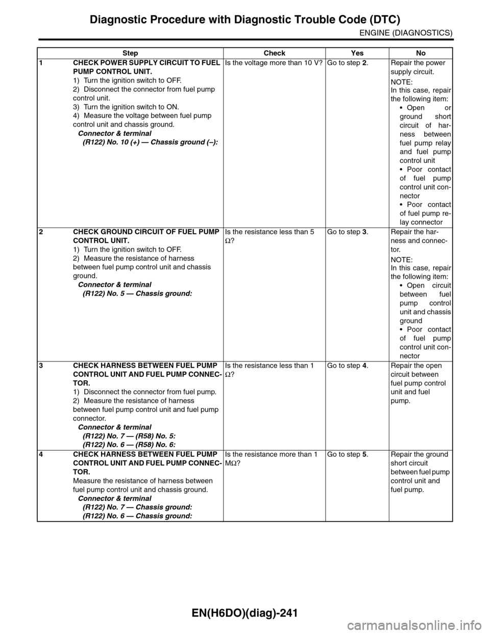
Step Check Yes No
1CHECK POWER SUPPLY CIRCUIT TO FUEL
PUMP CONTROL UNIT.
1) Turn the ignition switch to OFF.
2) Disconnect the connector from fuel pump
control unit.
3) Turn the ignition switch to ON.
4) Measure the voltage between fuel pump
control unit and chassis ground.
Connector & terminal
(R122) No. 10 (+) — Chassis ground (–):
Is the voltage more than 10 V? Go to step 2.Repair the power
supply circuit.
NOTE:
In this case, repair
the following item:
•Open or
ground short
circuit of har-
ness between
fuel pump relay
and fuel pump
control unit
•Poor contact
of fuel pump
control unit con-
nector
•Poor contact
of fuel pump re-
lay connector
2CHECK GROUND CIRCUIT OF FUEL PUMP
CONTROL UNIT.
1) Turn the ignition switch to OFF.
2) Measure the resistance of harness
between fuel pump control unit and chassis
ground.
Connector & terminal
(R122) No. 5 — Chassis ground:
Is the resistance less than 5
Ω?
Go to step 3.Repair the har-
ness and connec-
tor.
NOTE:
In this case, repair
the following item:
•Open circuit
between fuel
pump control
unit and chassis
ground
•Poor contact
of fuel pump
control unit con-
nector
3CHECK HARNESS BETWEEN FUEL PUMP
CONTROL UNIT AND FUEL PUMP CONNEC-
TOR.
1) Disconnect the connector from fuel pump.
2) Measure the resistance of harness
between fuel pump control unit and fuel pump
connector.
Connector & terminal
(R122) No. 7 — (R58) No. 5:
(R122) No. 6 — (R58) No. 6:
Is the resistance less than 1
Ω?
Go to step 4.Repair the open
circuit between
fuel pump control
unit and fuel
pump.
4CHECK HARNESS BETWEEN FUEL PUMP
CONTROL UNIT AND FUEL PUMP CONNEC-
TOR.
Measure the resistance of harness between
fuel pump control unit and chassis ground.
Connector & terminal
(R122) No. 7 — Chassis ground:
(R122) No. 6 — Chassis ground:
Is the resistance more than 1
MΩ?
Go to step 5.Repair the ground
short circuit
between fuel pump
control unit and
fuel pump.
Page 1403 of 2453

EN(H6DO)(diag)-242
Diagnostic Procedure with Diagnostic Trouble Code (DTC)
ENGINE (DIAGNOSTICS)
BN:DTC P0301 CYLINDER 1 MISFIRE DETECTED
NOTE:
For the diagnostic procedure, refer to DTC P0306.
MISFIRE DETECTED, Diagnostic Procedure with Diagnostic Trouble Code (DTC).>
BO:DTC P0302 CYLINDER 2 MISFIRE DETECTED
NOTE:
For the diagnostic procedure, refer to DTC P0306.
MISFIRE DETECTED, Diagnostic Procedure with Diagnostic Trouble Code (DTC).>
BP:DTC P0303 CYLINDER 3 MISFIRE DETECTED
NOTE:
For the diagnostic procedure, refer to DTC P0306.
MISFIRE DETECTED, Diagnostic Procedure with Diagnostic Trouble Code (DTC).>
BQ:DTC P0304 CYLINDER 4 MISFIRE DETECTED
NOTE:
For the diagnostic procedure, refer to DTC P0306.
MISFIRE DETECTED, Diagnostic Procedure with Diagnostic Trouble Code (DTC).>
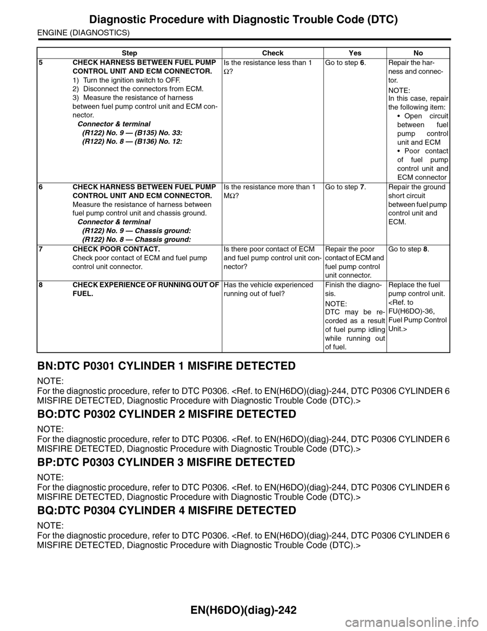
5CHECK HARNESS BETWEEN FUEL PUMP
CONTROL UNIT AND ECM CONNECTOR.
1) Turn the ignition switch to OFF.
2) Disconnect the connectors from ECM.
3) Measure the resistance of harness
between fuel pump control unit and ECM con-
nector.
Connector & terminal
(R122) No. 9 — (B135) No. 33:
(R122) No. 8 — (B136) No. 12:
Is the resistance less than 1
Ω?
Go to step 6.Repair the har-
ness and connec-
tor.
NOTE:In this case, repair
the following item:
•Open circuit
between fuel
pump control
unit and ECM
•Poor contact
of fuel pump
control unit and
ECM connector
6CHECK HARNESS BETWEEN FUEL PUMP
CONTROL UNIT AND ECM CONNECTOR.
Measure the resistance of harness between
fuel pump control unit and chassis ground.
Connector & terminal
(R122) No. 9 — Chassis ground:
(R122) No. 8 — Chassis ground:
Is the resistance more than 1
MΩ?
Go to step 7.Repair the ground
short circuit
between fuel pump
control unit and
ECM.
7CHECK POOR CONTACT.
Check poor contact of ECM and fuel pump
control unit connector.
Is there poor contact of ECM
and fuel pump control unit con-
nector?
Repair the poor
contact of ECM and
fuel pump control
unit connector.
Go to step 8.
8CHECK EXPERIENCE OF RUNNING OUT OF
FUEL.
Has the vehicle experienced
running out of fuel?
Finish the diagno-
sis.
NOTE:
DTC may be re-
corded as a result
of fuel pump idling
while running out
of fuel.
Replace the fuel
pump control unit.
FU(H6DO)-36,
Fuel Pump Control
Unit.>
Step Check Yes No