2009 SUBARU TRIBECA automatic transmission
[x] Cancel search: automatic transmissionPage 2078 of 2453
5AT-62
Torque Converter Assembly
AUTOMATIC TRANSMISSION
23.Torque Converter Assembly
A: REMOVAL
1) Remove the transmission assembly from vehicle
body.
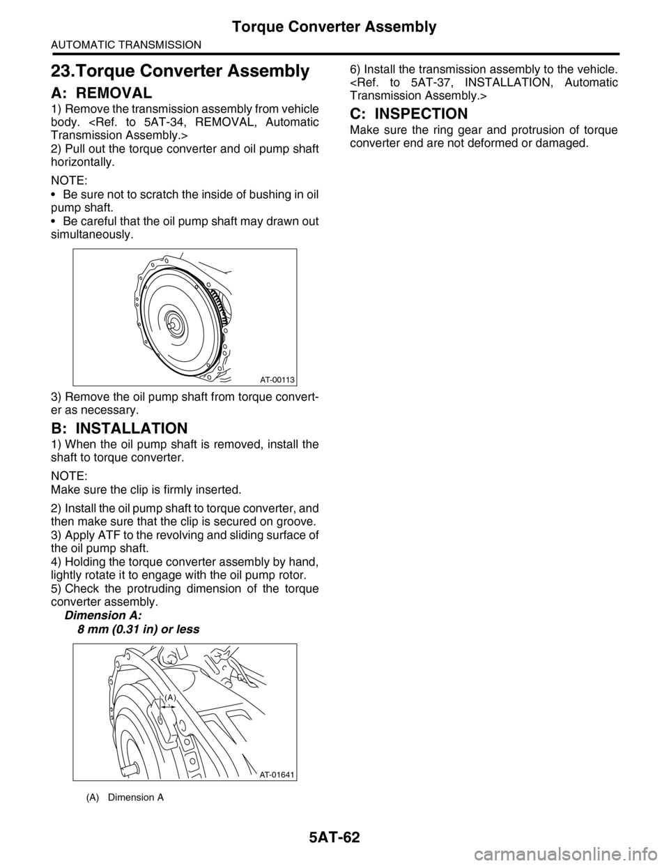
2) Pull out the torque converter and oil pump shaft
horizontally.
NOTE:
•Be sure not to scratch the inside of bushing in oil
pump shaft.
•Be careful that the oil pump shaft may drawn out
simultaneously.
3) Remove the oil pump shaft from torque convert-
er as necessary.
B: INSTALLATION
1) When the oil pump shaft is removed, install the
shaft to torque converter.
NOTE:
Make sure the clip is firmly inserted.
2) Install the oil pump shaft to torque converter, and
then make sure that the clip is secured on groove.
3) Apply ATF to the revolving and sliding surface of
the oil pump shaft.
4) Holding the torque converter assembly by hand,
lightly rotate it to engage with the oil pump rotor.
5) Check the protruding dimension of the torque
converter assembly.
Dimension A:
8 mm (0.31 in) or less
6) Install the transmission assembly to the vehicle.
C: INSPECTION
Make sure the ring gear and protrusion of torque
converter end are not deformed or damaged.
(A) Dimension A
AT-00113
AT-01641
(A)
Page 2079 of 2453
5AT-63
Extension Case
AUTOMATIC TRANSMISSION
24.Extension Case
A: REMOVAL
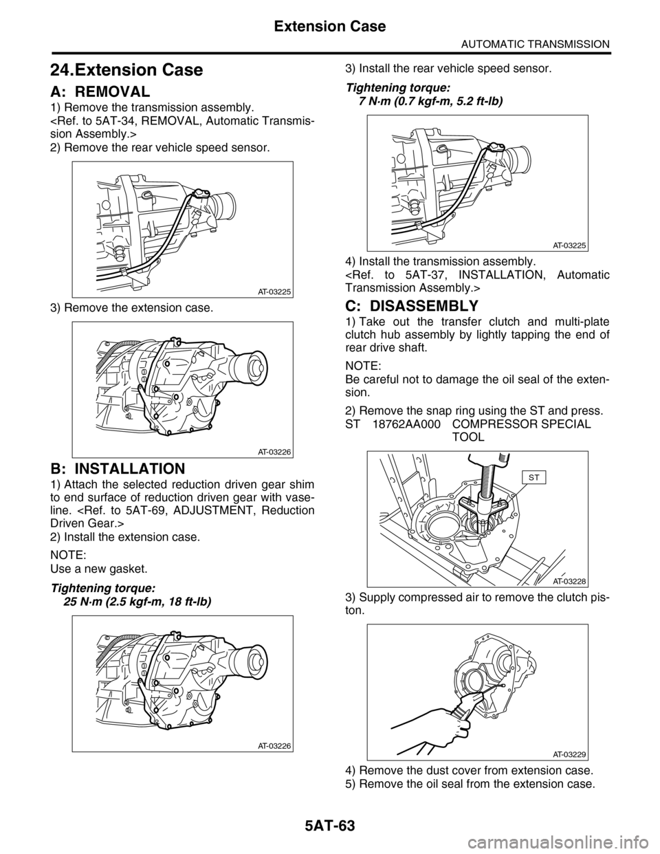
1) Remove the transmission assembly.
2) Remove the rear vehicle speed sensor.
3) Remove the extension case.
B: INSTALLATION
1) Attach the selected reduction driven gear shim
to end surface of reduction driven gear with vase-
line.
2) Install the extension case.
NOTE:
Use a new gasket.
Tightening torque:
25 N·m (2.5 kgf-m, 18 ft-lb)
3) Install the rear vehicle speed sensor.
Tightening torque:
7 N·m (0.7 kgf-m, 5.2 ft-lb)
4) Install the transmission assembly.
C: DISASSEMBLY
1) Take out the transfer clutch and multi-plate
clutch hub assembly by lightly tapping the end of
rear drive shaft.
NOTE:
Be careful not to damage the oil seal of the exten-
sion.
2) Remove the snap ring using the ST and press.
ST 18762AA000 COMPRESSOR SPECIAL
TOOL
3) Supply compressed air to remove the clutch pis-
ton.
4) Remove the dust cover from extension case.
5) Remove the oil seal from the extension case.
AT-03225
AT-03226
AT-03226
AT-03225
AT-03228
ST
AT-03229
Page 2080 of 2453
5AT-64
Extension Case
AUTOMATIC TRANSMISSION
D: ASSEMBLY
1) Press-fit the new oil seal using ST and the press.
ST 498057300 INSTALLER
2) Press-fit the dust cover.
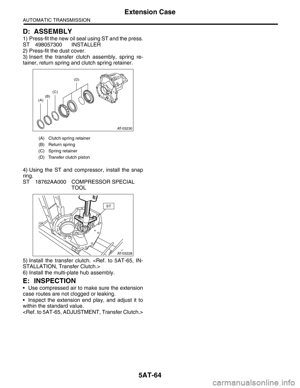
3) Insert the transfer clutch assembly, spring re-
tainer, return spring and clutch spring retainer.
4) Using the ST and compressor, install the snap
ring.
ST 18762AA000 COMPRESSOR SPECIAL
TOOL
5) Install the transfer clutch.
6) Install the multi-plate hub assembly.
E: INSPECTION
•Use compressed air to make sure the extension
case routes are not clogged or leaking.
•Inspect the extension end play, and adjust it to
within the standard value.
(A) Clutch spring retainer
(B) Return spring
(C) Spring retainer
(D) Transfer clutch piston
AT-03230
(A)(B)(C)
(D)
AT-03228
ST
Page 2081 of 2453
5AT-65
Transfer Clutch
AUTOMATIC TRANSMISSION
25.Transfer Clutch
A: REMOVAL
1) Remove the transmission assembly from vehicle
body.
2) Remove the extension case, and then remove
the transfer clutch.
B: INSTALLATION
1) Select the rear drive shaft shim.
2) Select driven plate No. 3.
3) Install the extension case.
4) Install the transmission assembly to the vehicle.
C: INSPECTION
•Inspect the drive plate facing for wear and dam-
age.
•Make sure the snap ring is not worn and the re-
turn spring has no permanent distortion, damage,
or deformation.
•Check that the D-ring is not damaged.
•Inspect the extension end play, and adjust it to
within the standard value.
D: ADJUSTMENT
1. REAR DRIVE SHAFT SHIM SELECTION
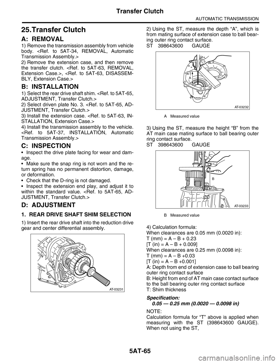
1) Insert the rear drive shaft into the reduction drive
gear and center differential assembly.
2) Using the ST, measure the depth “A”, which is
from mating surface of extension case to ball bear-
ing outer ring contact surface.
ST 398643600 GAUGE
3) Using the ST, measure the height “B” from the
AT main case mating surface to ball bearing outer
ring contact surface.
ST 398643600 GAUGE
4) Calculation formula:
When clearances are 0.05 mm (0.0020 in):
T (mm) = A – B + 0.23
[T (in) = A – B + 0.009]
When clearances are 0.25 mm (0.0098 in):
T (mm) = A – B +0.03
[T (in) = A – B +0.001]
A: Depth from end of extension case to ball bearing
outer ring contact surface
B: Height from end of AT main case contact surface
to the ball bearing outer ring contact surface
T: Shim thickness
Specification:
0.05 — 0.25 mm (0.0020 — 0.0098 in)
NOTE:
Calculation formula for “T” above is applied when
measuring with the ST (398643600 GAUGE).
When not using the ST,
AT-03231
AMeasured value
BMeasured value
AT-03232
A
AT-03233
B
Page 2082 of 2453
5AT-66
Transfer Clutch
AUTOMATIC TRANSMISSION
When clearances are 0.05 mm (0.0020 in):
T (mm) = (A – α) – ((B – β) – 0.28) – 0.05
[T (in) = (A – α) – ((B – β) – 0.011) – 0.0020]
When clearances are 0.25 mm (0.0098 in):
T (mm) = (A – α) – ((B – β) – 0.28) – 0.25
[T (in) = (A – α) – ((B – β) – 0.011) – 0.0098]
is applied.
T: Shim thickness
A: Depth from end of extension case to ball bearing
outer ring contact surface
B: Height from end of AT main case contact surface
to the ball bearing outer ring contact surface
α: Thickness of collar used when measuring “A”
β: Thickness of collar used when measuring “B”
0.28 (0.011): Gasket thickness (Unit mm (in))
2. SELECTION OF DRIVEN PLATE NO. 3
1) Install the drive plate and driven plate to the cen-
ter differential carrier.
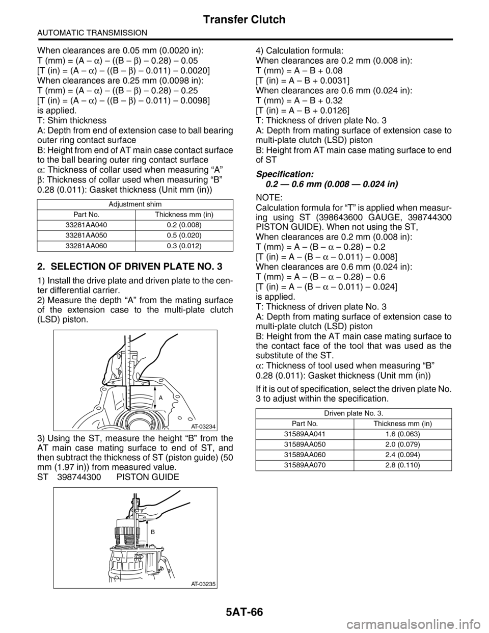
2) Measure the depth “A” from the mating surface
of the extension case to the multi-plate clutch
(LSD) piston.
3) Using the ST, measure the height “B” from the
AT main case mating surface to end of ST, and
then subtract the thickness of ST (piston guide) (50
mm (1.97 in)) from measured value.
ST 398744300 PISTON GUIDE
4) Calculation formula:
When clearances are 0.2 mm (0.008 in):
T (mm) = A – B + 0.08
[T (in) = A – B + 0.0031]
When clearances are 0.6 mm (0.024 in):
T (mm) = A – B + 0.32
[T (in) = A – B + 0.0126]
T: Thickness of driven plate No. 3
A: Depth from mating surface of extension case to
multi-plate clutch (LSD) piston
B: Height from AT main case mating surface to end
of ST
Specification:
0.2 — 0.6 mm (0.008 — 0.024 in)
NOTE:
Calculation formula for “T” is applied when measur-
ing using ST (398643600 GAUGE, 398744300
PISTON GUIDE). When not using the ST,
When clearances are 0.2 mm (0.008 in):
T (mm) = A – (B – α – 0.28) – 0.2
[T (in) = A – (B – α – 0.011) – 0.008]
When clearances are 0.6 mm (0.024 in):
T (mm) = A – (B – α – 0.28) – 0.6
[T (in) = A – (B – α – 0.011) – 0.024]
is applied.
T: Thickness of driven plate No. 3
A: Depth from mating surface of extension case to
multi-plate clutch (LSD) piston
B: Height from the AT main case mating surface to
the contact face of the tool that was used as the
substitute of the ST.
α: Thickness of tool used when measuring “B”
0.28 (0.011): Gasket thickness (Unit mm (in))
If it is out of specification, select the driven plate No.
3 to adjust within the specification.
Adjustment shim
Par t No. Thickness mm (in)
33281AA040 0.2 (0.008)
33281AA050 0.5 (0.020)
33281AA060 0.3 (0.012)
AT-03234
A
AT-03235
B
Driven plate No. 3.
Par t N o. Thickness mm (in)
31589AA041 1.6 (0.063)
31589AA050 2.0 (0.079)
31589AA060 2.4 (0.094)
31589AA070 2.8 (0.110)
Page 2083 of 2453
5AT-67
Rear Drive Shaft
AUTOMATIC TRANSMISSION
26.Rear Drive Shaft
A: REMOVAL
1) Remove the transmission assembly from vehicle
body.
2) Remove the rear vehicle speed sensor, and then
remove the extension case.
3) Pull out the rear driveshaft from center differen-
tial assembly.
4) Remove the drive plate and driven plate.
B: INSTALLATION
1) Select the shim.
2) Install drive plate and driven plate.
3) Insert the rear driveshaft into the center differen-
tial assembly.
4) Combine the extension case, and then install the
rear vehicle speed sensor.
5) Install the transmission assembly to the vehicle.
C: DISASSEMBLY
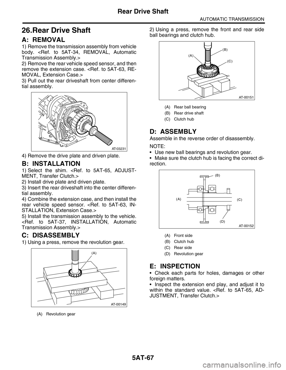
1) Using a press, remove the revolution gear.
2) Using a press, remove the front and rear side
ball bearings and clutch hub.
D: ASSEMBLY
Assemble in the reverse order of disassembly.
NOTE:
•Use new ball bearings and revolution gear.
•Make sure the clutch hub is facing the correct di-
rection.
E: INSPECTION
•Check each parts for holes, damages or other
foreign matters.
•Inspect the extension end play, and adjust it to
within the standard value.
(A) Revolution gear
AT-03231
AT-00149
(A)
(A) Rear ball bearing
(B) Rear drive shaft
(C) Clutch hub
(A) Front side
(B) Clutch hub
(C) Rear side
(D) Revolution gear
AT-00151
(A)
(B)
(C)
AT-00152
(A)
(B)
(C)
(D)
Page 2084 of 2453
5AT-68
Reduction Driven Gear
AUTOMATIC TRANSMISSION
27.Reduction Driven Gear
A: REMOVAL
1) Remove the transmission assembly from vehicle
body.
2) Remove the rear wheel speed sensor, and sep-
arate the extension case from transmission case.
3) Remove the center differential carrier.
4) Set the range select lever to the “P” range.
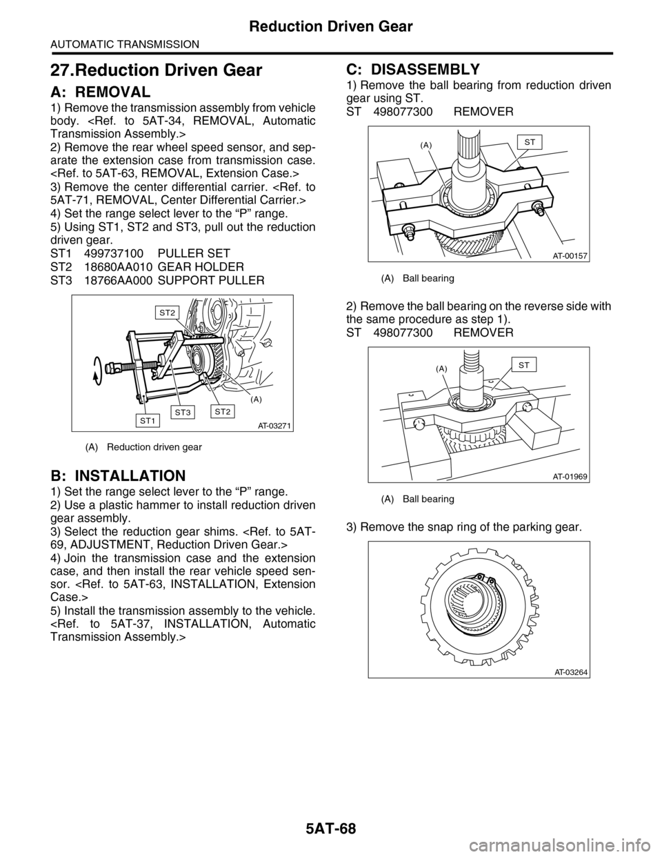
5) Using ST1, ST2 and ST3, pull out the reduction
driven gear.
ST1 499737100 PULLER SET
ST2 18680AA010 GEAR HOLDER
ST3 18766AA000 SUPPORT PULLER
B: INSTALLATION
1) Set the range select lever to the “P” range.
2) Use a plastic hammer to install reduction driven
gear assembly.
3) Select the reduction gear shims.
4) Join the transmission case and the extension
case, and then install the rear vehicle speed sen-
sor.
5) Install the transmission assembly to the vehicle.
C: DISASSEMBLY
1) Remove the ball bearing from reduction driven
gear using ST.
ST 498077300 REMOVER
2) Remove the ball bearing on the reverse side with
the same procedure as step 1).
ST 498077300 REMOVER
3) Remove the snap ring of the parking gear.
(A) Reduction driven gear
AT-03271
ST2ST1
ST2
ST3
(A)
(A) Ball bearing
(A) Ball bearing
AT-00157
(A)ST
AT-01969
(A)ST
AT-03264
Page 2085 of 2453
5AT-69
Reduction Driven Gear
AUTOMATIC TRANSMISSION
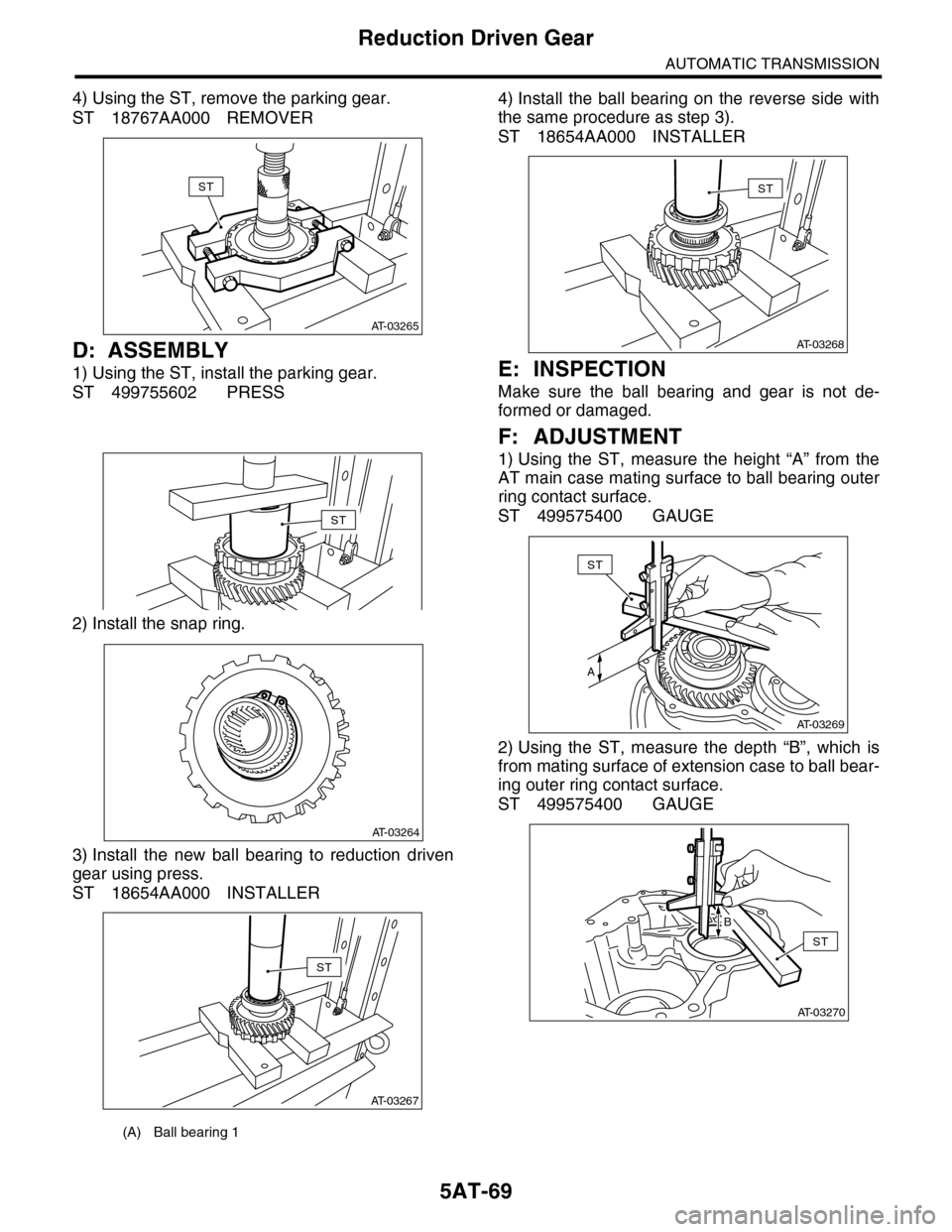
4) Using the ST, remove the parking gear.
ST 18767AA000 REMOVER
D: ASSEMBLY
1) Using the ST, install the parking gear.
ST 499755602 PRESS
2) Install the snap ring.
3) Install the new ball bearing to reduction driven
gear using press.
ST 18654AA000 INSTALLER
4) Install the ball bearing on the reverse side with
the same procedure as step 3).
ST 18654AA000 INSTALLER
E: INSPECTION
Make sure the ball bearing and gear is not de-
formed or damaged.
F: ADJUSTMENT
1) Using the ST, measure the height “A” from the
AT main case mating surface to ball bearing outer
ring contact surface.
ST 499575400 GAUGE
2) Using the ST, measure the depth “B”, which is
from mating surface of extension case to ball bear-
ing outer ring contact surface.
ST 499575400 GAUGE
(A) Ball bearing 1
AT-03265
ST
ST
AT-03264
AT-03267
ST
AT-03268
ST
AT-03269
ST
A
AT-03270
ST
B