2009 SUBARU TRIBECA engine
[x] Cancel search: enginePage 1833 of 2453
GD(H6DO)-221
Diagnostic Trouble Code (DTC) Detecting Criteria
GENERAL DESCRIPTION
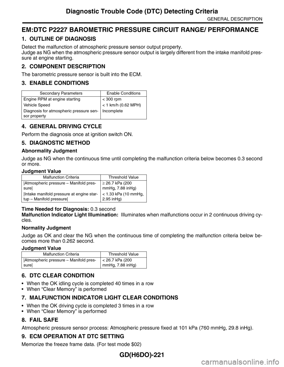
EM:DTC P2227 BAROMETRIC PRESSURE CIRCUIT RANGE/ PERFORMANCE
1. OUTLINE OF DIAGNOSIS
Detect the malfunction of atmospheric pressure sensor output property.
Judge as NG when the atmospheric pressure sensor output is largely different from the intake manifold pres-
sure at engine starting.
2. COMPONENT DESCRIPTION
The barometric pressure sensor is built into the ECM.
3. ENABLE CONDITIONS
4. GENERAL DRIVING CYCLE
Perform the diagnosis once at ignition switch ON.
5. DIAGNOSTIC METHOD
Abnormality Judgment
Judge as NG when the continuous time until completing the malfunction criteria below becomes 0.3 second
or more.
Time Needed for Diagnosis: 0.3 second
Malfunction Indicator Light Illumination: Illuminates when malfunctions occur in 2 continuous driving cy-
cles.
Normality Judgment
Judge as OK and clear the NG when the continuous time of completing the malfunction criteria below be-
comes more than 0.262 second.
6. DTC CLEAR CONDITION
•When the OK idling cycle is completed 40 times in a row
•When “Clear Memory” is performed
7. MALFUNCTION INDICATOR LIGHT CLEAR CONDITIONS
•When the OK driving cycle is completed 3 times in a row
•When “Clear Memory” is performed
8. FAIL SAFE
Atmospheric pressure sensor process: Atmospheric pressure fixed at 101 kPa (760 mmHg, 29.8 inHg).
9. ECM OPERATION AT DTC SETTING
Memorize the freeze frame data. (For test mode $02)
Secondary Parameters Enable Conditions
Engine RPM at engine starting < 300 rpm
Ve h i c l e S p e e d < 1 k m / h ( 0 . 6 2 M P H )
Diagnosis for atmospheric pressure sen-
sor property
Incomplete
Judgment Value
Malfunction Criteria Threshold Value
|Atmospheric pressure – Manifold pres-
sure|
≥ 26.7 kPa (200
mmHg, 7.88 inHg)
|Intake manifold pressure at engine star-
tup – Manifold pressure|
< 1.33 kPa (10 mmHg,
2.95 inHg)
Judgment Value
Malfunction Criteria Threshold Value
|Atmospheric pressure – Manifold pres-
sure|
< 26.7 kPa (200
mmHg, 7.88 inHg)
Page 1839 of 2453
IG(H6DO)-4
Spark Plug
IGNITION
2. Spark Plug
A: REMOVAL
CAUTION:
All spark plugs installed on an engine must be
of the same heat range.
Spark plug:
1. RH SIDE
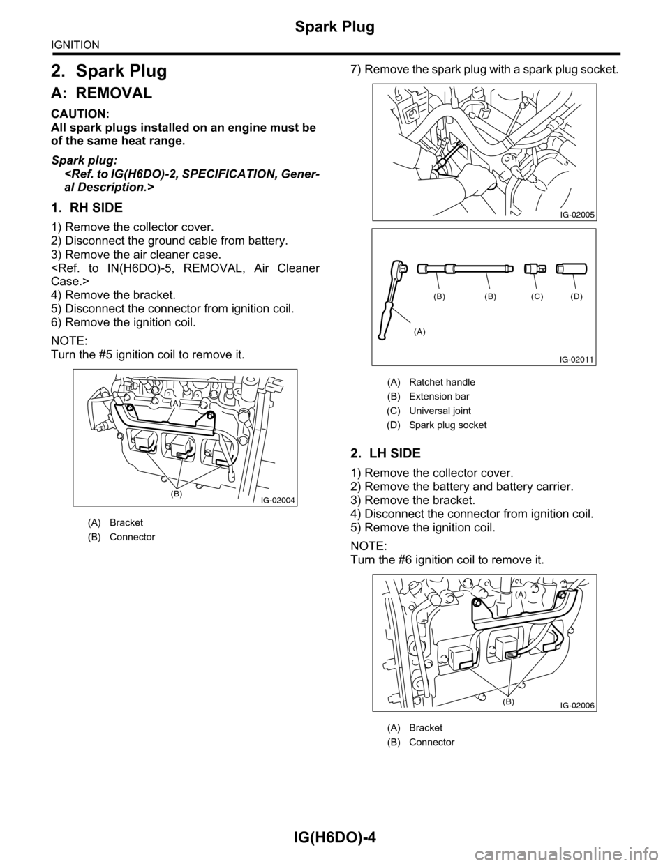
1) Remove the collector cover.
2) Disconnect the ground cable from battery.
3) Remove the air cleaner case.
4) Remove the bracket.
5) Disconnect the connector from ignition coil.
6) Remove the ignition coil.
NOTE:
Turn the #5 ignition coil to remove it.
7) Remove the spark plug with a spark plug socket.
2. LH SIDE
1) Remove the collector cover.
2) Remove the battery and battery carrier.
3) Remove the bracket.
4) Disconnect the connector from ignition coil.
5) Remove the ignition coil.
NOTE:
Turn the #6 ignition coil to remove it.
(A) Bracket
(B) Connector
IG-02004(B)
(A)
(A) Ratchet handle
(B) Extension bar
(C) Universal joint
(D) Spark plug socket
(A) Bracket
(B) Connector
IG-02005
(D)(C)(B)(B)
(A)
IG-02011
IG-02006
(A)
(B)
Page 1841 of 2453
IG(H6DO)-6
Spark Plug
IGNITION
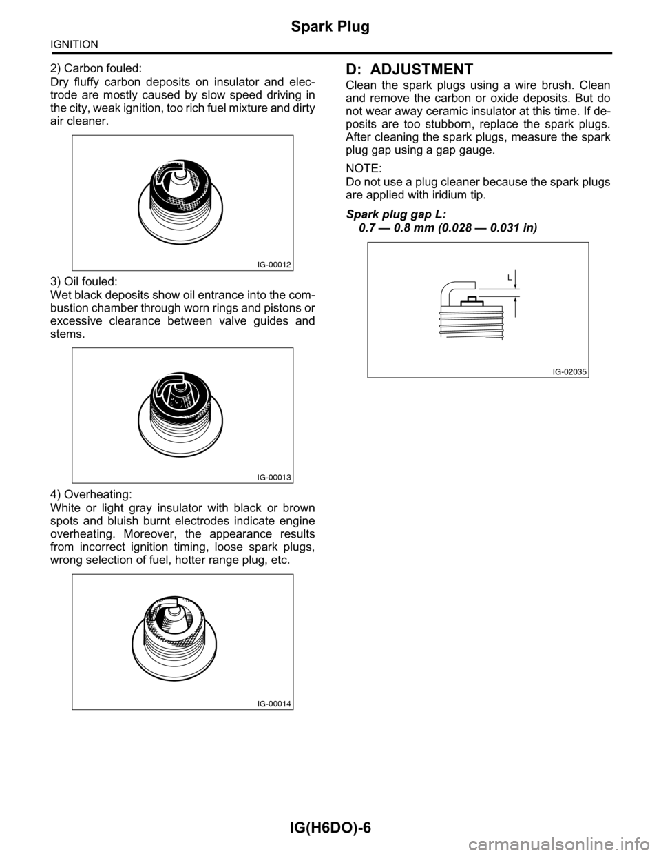
2) Carbon fouled:
Dry fluffy carbon deposits on insulator and elec-
trode are mostly caused by slow speed driving in
the city, weak ignition, too rich fuel mixture and dirty
air cleaner.
3) Oil fouled:
Wet black deposits show oil entrance into the com-
bustion chamber through worn rings and pistons or
excessive clearance between valve guides and
stems.
4) Overheating:
White or light gray insulator with black or brown
spots and bluish burnt electrodes indicate engine
overheating. Moreover, the appearance results
from incorrect ignition timing, loose spark plugs,
wrong selection of fuel, hotter range plug, etc.
D: ADJUSTMENT
Clean the spark plugs using a wire brush. Clean
and remove the carbon or oxide deposits. But do
not wear away ceramic insulator at this time. If de-
posits are too stubborn, replace the spark plugs.
After cleaning the spark plugs, measure the spark
plug gap using a gap gauge.
NOTE:
Do not use a plug cleaner because the spark plugs
are applied with iridium tip.
Spark plug gap L:
0.7 — 0.8 mm (0.028 — 0.031 in)
IG-00012
IG-00013
IG-00014
IG-02035
L
Page 1842 of 2453
IG(H6DO)-7
Ignition Coil & Ignitor Assembly
IGNITION
3. Ignition Coil & Ignitor Assem-
bly
A: REMOVAL
Direct ignition type has been adopted. Refer to
“Spark Plug” for removal procedure.
B: INSTALLATION
Install in the reverse order of removal.
Tightening torque:
16 N·m (1.6 kgf-m, 11.7 ft-lb)
C: INSPECTION
For inspection procedure, refer to “Diagnostics for
Engine Starting Failure.”
for Engine Starting Failure.>
Page 1851 of 2453
LU(H6DO)-2
General Description
LUBRICATION
1. General Description
A: SPECIFICATION
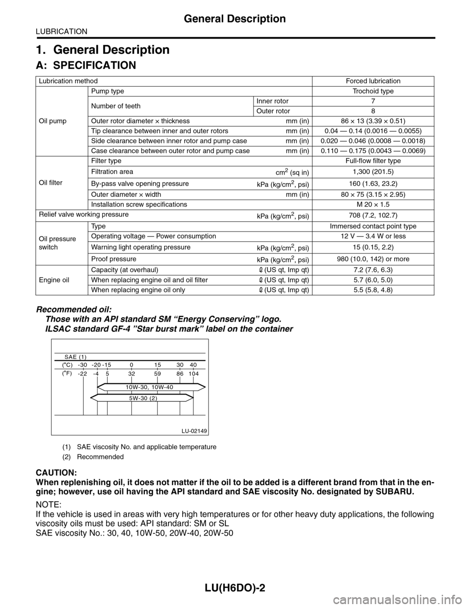
Recommended oil:
Those with an API standard SM “Energy Conserving” logo.
ILSAC standard GF-4 ”Star burst mark” label on the container
CAUTION:
When replenishing oil, it does not matter if the oil to be added is a different brand from that in the en-
gine; however, use oil having the API standard and SAE viscosity No. designated by SUBARU.
NOTE:
If the vehicle is used in areas with very high temperatures or for other heavy duty applications, the following
viscosity oils must be used: API standard: SM or SL
SAE viscosity No.: 30, 40, 10W-50, 20W-40, 20W-50
Lubrication methodForced lubr ication
Oil pump
Pump typeTr o c h o i d t y p e
Number of teethInner rotor 7
Outer rotor 8
Outer rotor diameter × thickness mm (in) 86 × 13 (3.39 × 0.51)
Tip clearance between inner and outer rotors mm (in) 0.04 — 0.14 (0.0016 — 0.0055)
Side clearance between inner rotor and pump case mm (in) 0.020 — 0.046 (0.0008 — 0.0018)
Case clearance between outer rotor and pump case mm (in) 0.110 — 0.175 (0.0043 — 0.0069)
Oil filter
Filter typeFull-flow filter type
Filtration areacm2 (sq in)1,300 (201.5)
By-pass valve opening pressurekPa (kg/cm2, psi)160 (1.63, 23.2)
Outer diameter × width mm (in) 80 × 75 (3.15 × 2.95)
Installation screw specifications M 20 × 1.5
Relief valve working pressurekPa (kg/cm2, psi)708 (7.2, 102.7)
Oil pressure
switch
Ty p eImmersed contact point type
Operating voltage — Power consumption 12 V — 3.4 W or less
Wa r ni n g l ig h t o p era t i ng pr e ss ur ekPa (kg/cm2, psi)15 (0.15, 2.2)
Proof pressurekPa (kg/cm2, psi)980 (10.0, 142) or more
Engine oil
Capacity (at overhaul)2(US qt, Imp qt) 7.2 (7.6, 6.3)
When replacing engine oil and oil filter2(US qt, Imp qt) 5.7 (6.0, 5.0)
When replacing engine oil only2(US qt, Imp qt) 5.5 (5.8, 4.8)
(1) SAE viscosity No. and applicable temperature
(2) Recommended
LU-02149
( C) -30 -20 -15 0 15 30 40
-22 -4 5 32 59 86 104
SAE (1)
( F)
5W-30 (2)
10W-30, 10W-40
Page 1855 of 2453
LU(H6DO)-6
Oil Pressure System
LUBRICATION
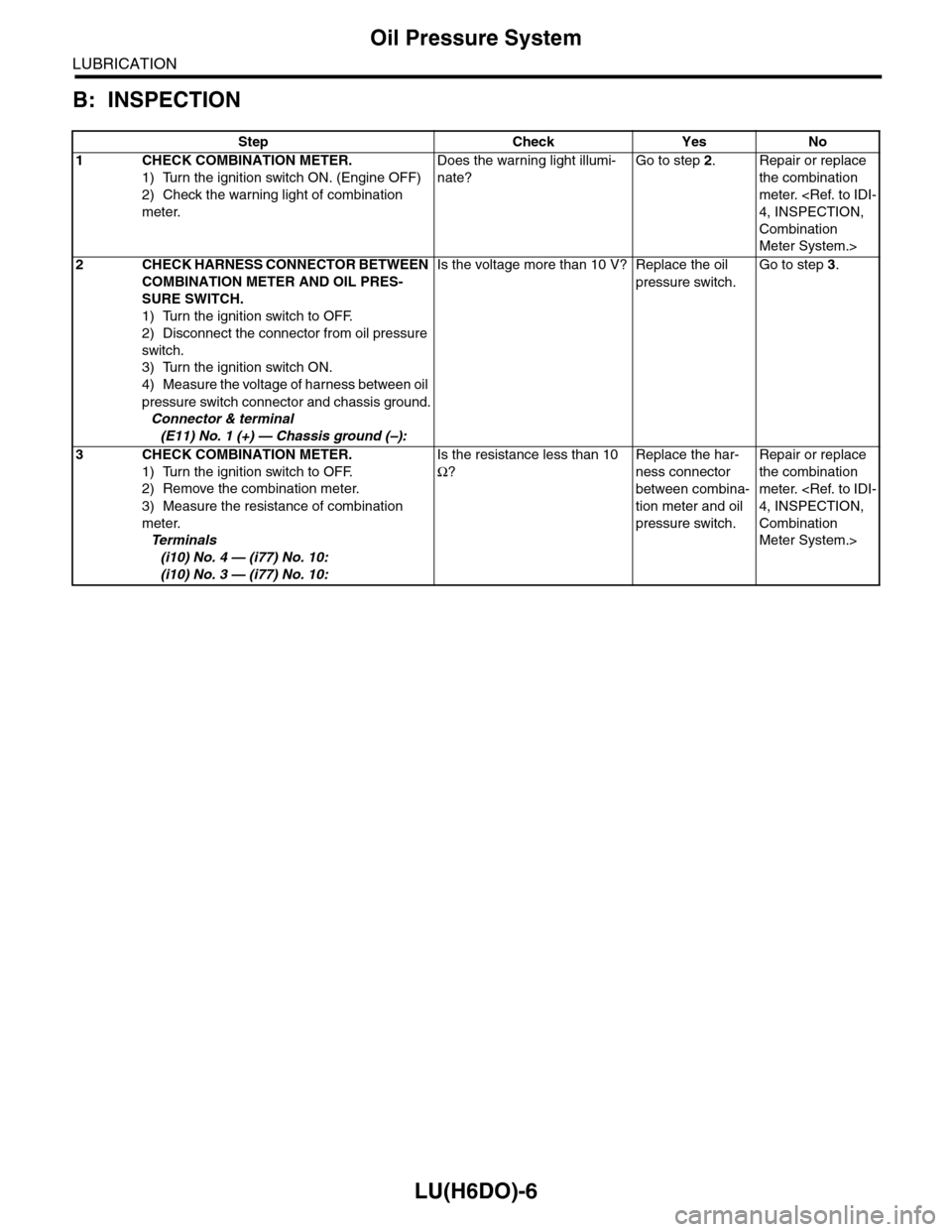
B: INSPECTION
Step Check Yes No
1CHECK COMBINATION METER.
1) Turn the ignition switch ON. (Engine OFF)
2) Check the warning light of combination
meter.
Does the warning light illumi-
nate?
Go to step 2.Repair or replace
the combination
meter.
Combination
Meter System.>
2CHECK HARNESS CONNECTOR BETWEEN
COMBINATION METER AND OIL PRES-
SURE SWITCH.
1) Turn the ignition switch to OFF.
2) Disconnect the connector from oil pressure
switch.
3) Turn the ignition switch ON.
4) Measure the voltage of harness between oil
pressure switch connector and chassis ground.
Connector & terminal
(E11) No. 1 (+) — Chassis ground (–):
Is the voltage more than 10 V? Replace the oil
pressure switch.
Go to step 3.
3CHECK COMBINATION METER.
1) Turn the ignition switch to OFF.
2) Remove the combination meter.
3) Measure the resistance of combination
meter.
Te r m i n a l s
(i10) No. 4 — (i77) No. 10:
(i10) No. 3 — (i77) No. 10:
Is the resistance less than 10
Ω?
Replace the har-
ness connector
between combina-
tion meter and oil
pressure switch.
Repair or replace
the combination
meter.
Combination
Meter System.>
Page 1856 of 2453
LU(H6DO)-7
Engine Oil
LUBRICATION
3. Engine Oil
A: INSPECTION
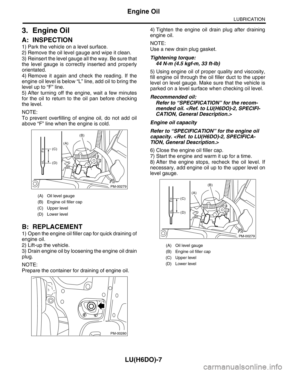
1) Park the vehicle on a level surface.
2) Remove the oil level gauge and wipe it clean.
3) Reinsert the level gauge all the way. Be sure that
the level gauge is correctly inserted and properly
orientated.
4) Remove it again and check the reading. If the
engine oil level is below “L” line, add oil to bring the
level up to “F” line.
5) After turning off the engine, wait a few minutes
for the oil to return to the oil pan before checking
the level.
NOTE:
To prevent overfilling of engine oil, do not add oil
above “F” line when the engine is cold.
B: REPLACEMENT
1) Open the engine oil filler cap for quick draining of
engine oil.
2) Lift-up the vehicle.
3) Drain engine oil by loosening the engine oil drain
plug.
NOTE:
Prepare the container for draining of engine oil.
4) Tighten the engine oil drain plug after draining
engine oil.
NOTE:
Use a new drain plug gasket.
Tightening torque:
44 N·m (4.5 kgf-m, 33 ft-lb)
5) Using engine oil of proper quality and viscosity,
fill engine oil through the oil filler duct to the upper
level on level gauge. Make sure that the vehicle is
parked on a level surface when checking oil level.
Recommended oil:
Refer to “SPECIFICATION” for the recom-
mended oil.
Engine oil capacity
Refer to “SPECIFICATION” for the engine oil
capacity.
6) Close the engine oil filler cap.
7) Start the engine and warm it up for a time.
8) After the engine stops, recheck the oil level. If
necessary, add engine oil up to the upper level on
level gauge.
(A) Oil level gauge
(B) Engine oil filler cap
(C) Upper level
(D) Lower level
PM-00279
(A)
(B)
(C)
(D)
PM-00280
(A) Oil level gauge
(B) Engine oil filler cap
(C) Upper level
(D) Lower level
PM-00279
(A)
(B)
(C)
(D)
Page 1857 of 2453
LU(H6DO)-8
Oil Pump
LUBRICATION
4. Oil Pump
A: REMOVAL
1) Remove the collector cover.
2) Disconnect the ground cable from battery.
3) Lift-up the vehicle.
4) Remove the under cover.
5) Drain engine coolant.
MENT, Engine Coolant.>
6) Lower the vehicle.
7) Remove the radiator.
8) Remove the V-belts.
9) Remove the front chain cover.
10) Remove the timing chain.
11) Remove the crank sprocket.
12) Remove the oil pump cover.
13) Remove the inner rotor and outer rotor.
B: INSTALLATION
1) Apply a coat of engine oil to the whole area of in-
ner rotor and outer rotor.
2) Set the inner rotor onto opening edge of crank
shaft, and install the inner rotor, and then assemble
the outer rotor.
3) Install the oil pump cover.
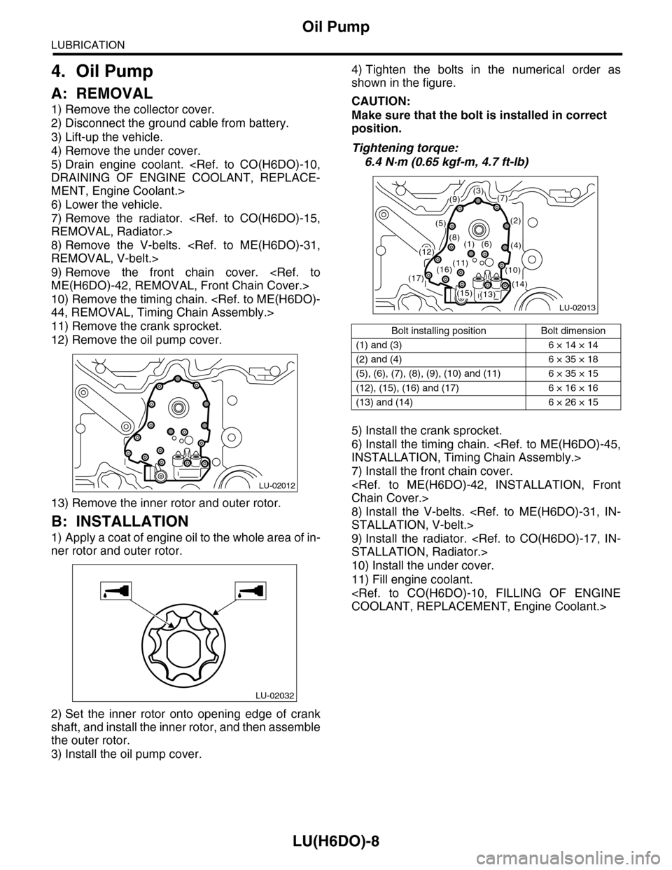
4) Tighten the bolts in the numerical order as
shown in the figure.
CAUTION:
Make sure that the bolt is installed in correct
position.
Tightening torque:
6.4 N·m (0.65 kgf-m, 4.7 ft-lb)
5) Install the crank sprocket.
6) Install the timing chain.
7) Install the front chain cover.
8) Install the V-belts.
9) Install the radiator.
10) Install the under cover.
11) Fill engine coolant.
LU-02012
LU-02032
Bolt installing position Bolt dimension
(1) and (3) 6 × 14 × 14
(2) and (4) 6 × 35 × 18
(5), (6), (7), (8), (9), (10) and (11) 6 × 35 × 15
(12), (15), (16) and (17) 6 × 16 × 16
(13) and (14) 6 × 26 × 15
LU-02013
(3)(7)
(2)
(4)
(9)
(5)
(8)(1)(6)(12)
(13)(14)(15)
(16)(17)
(11)(10)