2009 SUBARU TRIBECA ERROR
[x] Cancel search: ERRORPage 976 of 2453

TPM(diag)-26
List of Diagnostic Trouble Code (DTC)
TIRE PRESSURE MONITORING SYSTEM (DIAGNOSTICS)
10.List of Diagnostic Trouble Code (DTC)
A: LIST
DTC Item Contents of diagnosis Remarks
11 FL air pressure decrease FL tire pressure is reduced.
with Diagnostic Trouble Code (DTC).>
12 FR air pressure decrease FR tire pressure is reduced.
dure with Diagnostic Trouble Code (DTC).>
13 RR air pressure decrease RR tire pressure is reduced.
dure with Diagnostic Trouble Code (DTC).>
14 RL air pressure decrease RL tire pressure is reduced.
with Diagnostic Trouble Code (DTC).>
21 No FL transmitter dataData cannot be received from FL
sensor.
with Diagnostic Trouble Code (DTC).>
22 No FR transmitter dataData cannot be received from FR
sensor.
with Diagnostic Trouble Code (DTC).>
23 No RR transmitter dataData cannot be received from RR
sensor.
with Diagnostic Trouble Code (DTC).>
24 No RL transmitter dataData cannot be received from RL
sensor.
with Diagnostic Trouble Code (DTC).>
31 FL transmit pres data abnormal.FL sensor data contents are
abnormal.
cedure with Diagnostic Trouble Code (DTC).>
32FR transmitter pres data abnor-
mal.
FR sensor data contents are
abnormal.
cedure with Diagnostic Trouble Code (DTC).>
33 RR transmit pres data abnormal.RR sensor data contents are
abnormal.
cedure with Diagnostic Trouble Code (DTC).>
34 RL transmit pres data abnormal.RL sensor data contents are
abnormal.
cedure with Diagnostic Trouble Code (DTC).>
41 FL trans function code abnormal. Function code has error.
Procedure with Diagnostic Trouble Code
(DTC).>
42 FR trans function code abnormal. Function code has error.
Procedure with Diagnostic Trouble Code
(DTC).>
43 RR trans function code abnormal. Function code has error.
Procedure with Diagnostic Trouble Code
(DTC).>
44 RL trans function code abnormal. Function code has error.
Procedure with Diagnostic Trouble Code
(DTC).>
Page 1197 of 2453
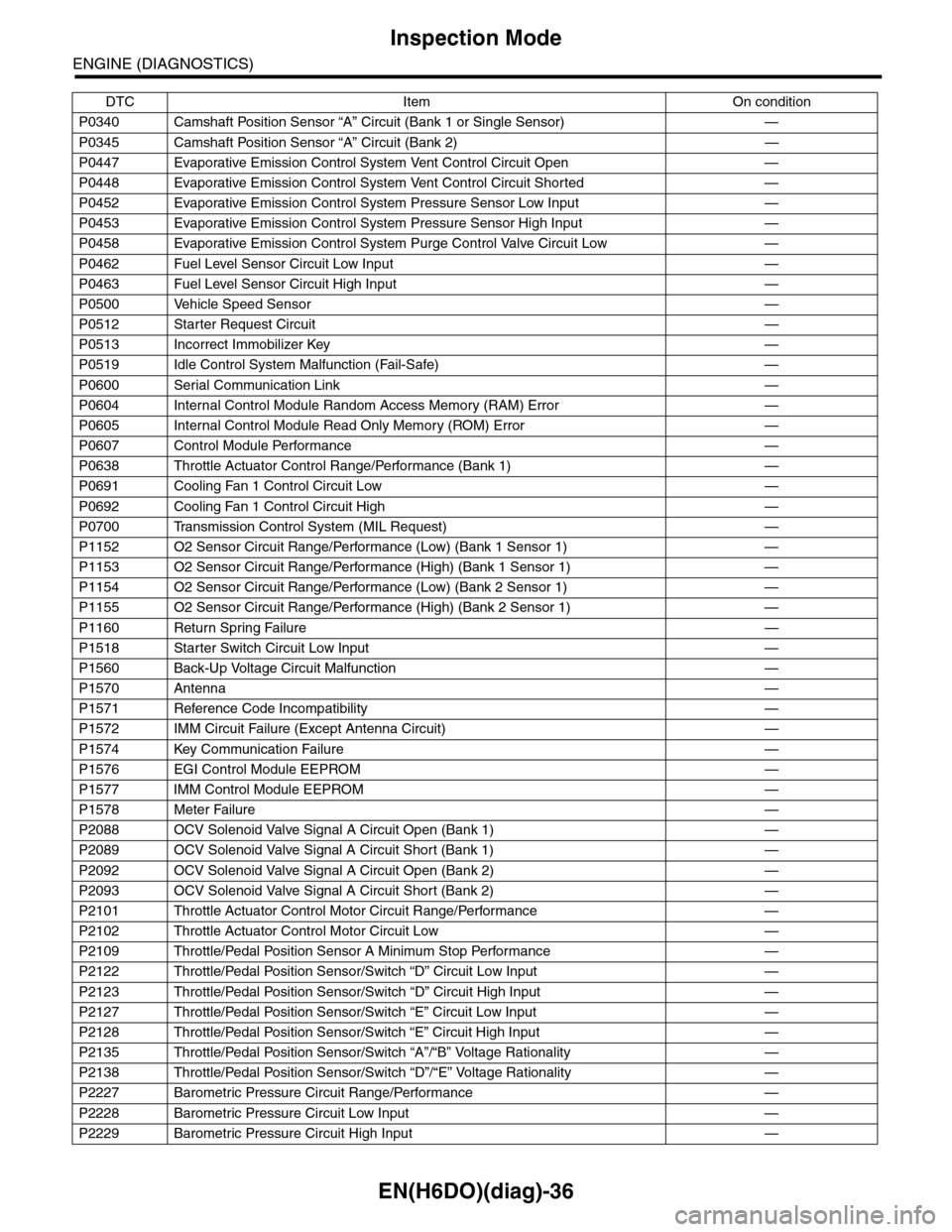
EN(H6DO)(diag)-36
Inspection Mode
ENGINE (DIAGNOSTICS)
P0340 Camshaft Position Sensor “A” Circuit (Bank 1 or Single Sensor) —
P0345 Camshaft Position Sensor “A” Circuit (Bank 2) —
P0447 Evaporative Emission Control System Vent Control Circuit Open —
P0448 Evaporative Emission Control System Vent Control Circuit Shorted —
P0452 Evaporative Emission Control System Pressure Sensor Low Input —
P0453 Evaporative Emission Control System Pressure Sensor High Input —
P0458 Evaporative Emission Control System Purge Control Valve Circuit Low —
P0462 Fuel Level Sensor Circuit Low Input —
P0463 Fuel Level Sensor Circuit High Input —
P0500 Vehicle Speed Sensor—
P0512 Starter Request Circuit—
P0513 Incorrect Immobilizer Key —
P0519 Idle Control System Malfunction (Fail-Safe) —
P0600 Serial Communication Link —
P0604 Internal Control Module Random Access Memory (RAM) Error —
P0605 Internal Control Module Read Only Memory (ROM) Error —
P0607 Control Module Performance —
P0638 Throttle Actuator Control Range/Performance (Bank 1) —
P0691 Cooling Fan 1 Control Circuit Low —
P0692 Cooling Fan 1 Control Circuit High —
P0700 Transmission Control System (MIL Request) —
P1152 O2 Sensor Circuit Range/Performance (Low) (Bank 1 Sensor 1) —
P1153 O2 Sensor Circuit Range/Performance (High) (Bank 1 Sensor 1) —
P1154 O2 Sensor Circuit Range/Performance (Low) (Bank 2 Sensor 1) —
P1155 O2 Sensor Circuit Range/Performance (High) (Bank 2 Sensor 1) —
P1160 Return Spring Failure—
P1518 Starter Switch Circuit Low Input —
P1560 Back-Up Voltage Circuit Malfunction —
P1570 Antenna—
P1571 Reference Code Incompatibility —
P1572 IMM Circuit Failure (Except Antenna Circuit) —
P1574 Key Communication Failure —
P1576 EGI Control Module EEPROM —
P1577 IMM Control Module EEPROM —
P1578 Meter Failure—
P2088 OCV Solenoid Valve Signal A Circuit Open (Bank 1) —
P2089 OCV Solenoid Valve Signal A Circuit Short (Bank 1) —
P2092 OCV Solenoid Valve Signal A Circuit Open (Bank 2) —
P2093 OCV Solenoid Valve Signal A Circuit Short (Bank 2) —
P2101 Throttle Actuator Control Motor Circuit Range/Performance —
P2102 Throttle Actuator Control Motor Circuit Low —
P2109 Throttle/Pedal Position Sensor A Minimum Stop Performance —
P2122 Throttle/Pedal Position Sensor/Switch “D” Circuit Low Input —
P2123 Throttle/Pedal Position Sensor/Switch “D” Circuit High Input —
P2127 Throttle/Pedal Position Sensor/Switch “E” Circuit Low Input —
P2128 Throttle/Pedal Position Sensor/Switch “E” Circuit High Input —
P2135 Throttle/Pedal Position Sensor/Switch “A”/“B” Voltage Rationality —
P2138 Throttle/Pedal Position Sensor/Switch “D”/“E” Voltage Rationality —
P2227 Barometric Pressure Circuit Range/Performance —
P2228 Barometric Pressure Circuit Low Input —
P2229 Barometric Pressure Circuit High Input —
DTC Item On condition
Page 1235 of 2453
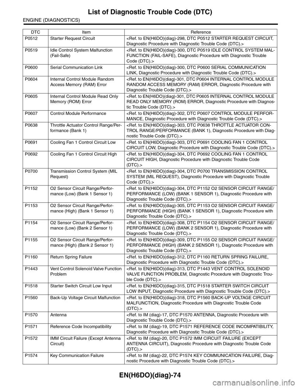
EN(H6DO)(diag)-74
List of Diagnostic Trouble Code (DTC)
ENGINE (DIAGNOSTICS)
P0512 Starter Request Circuit
P0519 Idle Control System Malfunction
(Fail-Safe)
Code (DTC).>
P0600 Serial Communication Link
P0604 Internal Control Module Random
Access Memory (RAM) Error
Diagnostic Trouble Code (DTC).>
P0605 Internal Control Module Read Only
Memory (ROM) Error
tic Trouble Code (DTC).>
P0607 Control Module Performance
P0638 Throttle Actuator Control Range/Per-
for mance (Bank 1)
nostic Trouble Code (DTC).>
P0691 Cooling Fan 1 Control Circuit Low
P0692 Cooling Fan 1 Control Circuit High
(DTC).>
P0700 Transmission Control System (MIL
Request)
Code (DTC).>
P1152 O2 Sensor Circuit Range/Perfor-
mance (Low) (Bank 1 Sensor 1)
Diagnostic Trouble Code (DTC).>
P1153 O2 Sensor Circuit Range/Perfor-
mance (High) (Bank 1 Sensor 1)
Diagnostic Trouble Code (DTC).>
P1154 O2 Sensor Circuit Range/Perfor-
mance (Low) (Bank 2 Sensor 1)
Diagnostic Trouble Code (DTC).>
P1155 O2 Sensor Circuit Range/Perfor-
mance (High) (Bank 2 Sensor 1)
Diagnostic Trouble Code (DTC).>
P1160 Return Spring Failure
P1443 Vent Control Solenoid Valve Function
Problem
ble Code (DTC).>
P1518 Starter Switch Circuit Low Input
P1560 Back-Up Voltage Circuit Malfunction
(DTC).>
P1570 Antenna
P1571 Reference Code Incompatibility
P1572 IMM Circuit Failure (Except Antenna
Circuit)
(DTC).>
P1574 Key Communication Failure
DTC Item Reference
Page 1462 of 2453
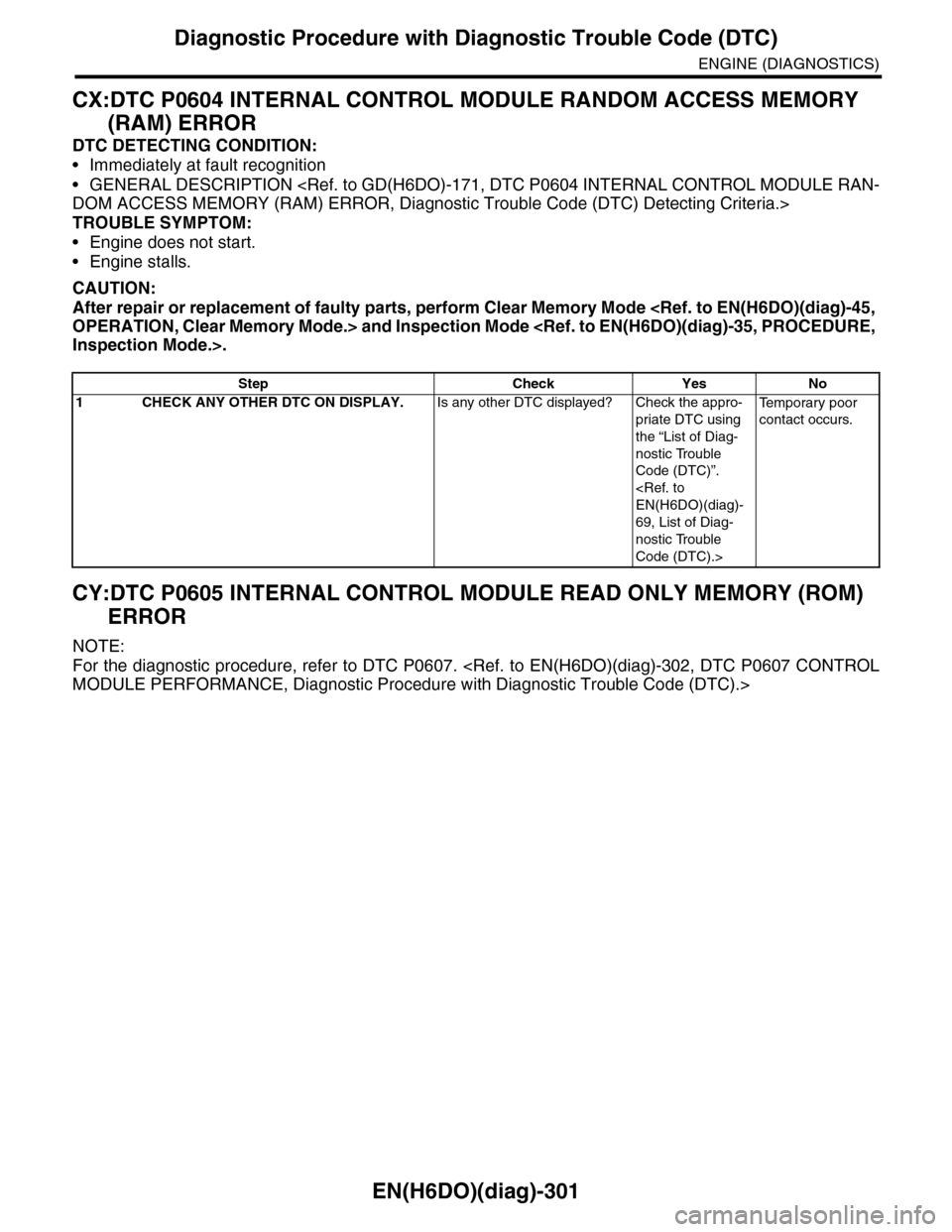
EN(H6DO)(diag)-301
Diagnostic Procedure with Diagnostic Trouble Code (DTC)
ENGINE (DIAGNOSTICS)
CX:DTC P0604 INTERNAL CONTROL MODULE RANDOM ACCESS MEMORY
(RAM) ERROR
DTC DETECTING CONDITION:
•Immediately at fault recognition
•GENERAL DESCRIPTION
TROUBLE SYMPTOM:
•Engine does not start.
•Engine stalls.
CAUTION:
After repair or replacement of faulty parts, perform Clear Memory Mode
CY:DTC P0605 INTERNAL CONTROL MODULE READ ONLY MEMORY (ROM)
ERROR
NOTE:
For the diagnostic procedure, refer to DTC P0607.
Step Check Yes No
1CHECK ANY OTHER DTC ON DISPLAY.Is any other DTC displayed? Check the appro-
priate DTC using
the “List of Diag-
nostic Trouble
Code (DTC)”.
69, List of Diag-
nostic Trouble
Code (DTC).>
Te m p o r a r y p o o r
contact occurs.
Page 1618 of 2453
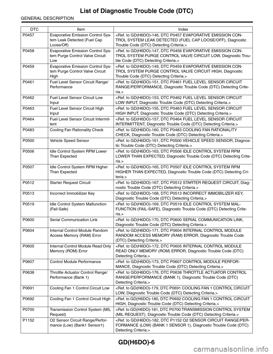
GD(H6DO)-6
List of Diagnostic Trouble Code (DTC)
GENERAL DESCRIPTION
P0457 Evaporative Emission Control Sys-
tem Leak Detected (Fuel Cap
Loose/Off)
Tr o u b l e C o d e ( D T C ) D e t e c t i n g C r i t e r i a . >
P0458 Evaporative Emission Control Sys-
tem Purge Control Valve Circuit
Low
ble Code (DTC) Detecting Criteria.>
P0459 Evaporative Emission Control Sys-
tem Purge Control Valve Circuit
High
Tr o u b l e C o d e ( D T C ) D e t e c t i n g C r i t e r i a . >
P0461 Fuel Level Sensor Circuit Range/
Per fo r m an ce
ria.>
P0462 Fuel Level Sensor Circuit Low
Input
P0463 Fuel Level Sensor Circuit High
Input
P0464 Fuel Level Sensor Circuit Intermit-
tent
P0483 Cooling Fan Rationality Check
P0500 Vehicle Speed Sensor
P0506 Idle Control System RPM Lower
Than Expected
ria.>
P0507 Idle Control System RPM Higher
Than Expected
teria.>
P0512 Starter Request Circuit
P0513 Incorrect Immobilizer Key
P0519 Idle Control System Malfunction
(Fail-Safe)
ria.>
P0600 Serial Communication Link
P0604 Internal Control Module Random
Access Memory (RAM) Error
(DTC) Detecting Criteria.>
P0605 Internal Control Module Read Only
Memory (ROM) Error
Detecting Criteria.>
P0607 Control Module Performance
P0638 Throttle Actuator Control Range/
Per fo r m an ce ( B an k 1 )
Detecting Criteria.>
P0691 Cooling Fan 1 Control Circuit Low
P0692 Cooling Fan 1 Control Circuit High
P0700 Transmission Control System (MIL
Request)
P1152 O2 Sensor Circuit Range/Perfor-
mance (Low) (Bank1 Sensor1)
Detecting Criteria.>
DTC Item Index
Page 1627 of 2453
GD(H6DO)-15
Diagnostic Trouble Code (DTC) Detecting Criteria
GENERAL DESCRIPTION
F: DTC P0028 INTAKE VALVE CONTROL SOLENOID CIRCUIT RANGE/PER-
FORMANCE (BANK 2)
NOTE:
For diagnostic procedures, refer to DTC P0026.
Criteria.>
G: DTC P0030 HO2S HEATER CONTROL CIRCUIT (BANK 1 SENSOR 1)
1. OUTLINE OF DIAGNOSIS
Detect functional errors of the front oxygen (A/F) sensor heater.
Judge as NG when it is determined that the front oxygen (A/F) sensor impedance is large when looking at en-
gine status such as deceleration fuel cut.
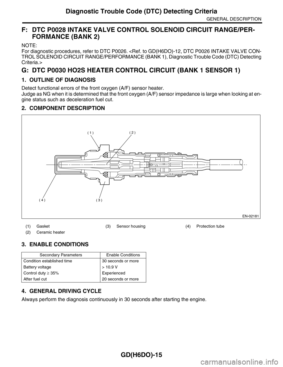
2. COMPONENT DESCRIPTION
3. ENABLE CONDITIONS
4. GENERAL DRIVING CYCLE
Always perform the diagnosis continuously in 30 seconds after starting the engine.
(1) Gasket (3) Sensor housing (4) Protection tube
(2) Ceramic heater
Secondary Parameters Enable Conditions
Condition established time 30 seconds or more
Battery voltage > 10.9 V
Control duty ≥ 35% Experienced
After fuel cut 20 seconds or more
EN-02181
( 1 )( 2 )
( 3 )( 4 )
Page 1629 of 2453
GD(H6DO)-17
Diagnostic Trouble Code (DTC) Detecting Criteria
GENERAL DESCRIPTION
H: DTC P0031 HO2S HEATER CONTROL CIRCUIT LOW (BANK 1 SENSOR 1)
1. OUTLINE OF DIAGNOSIS
Detect the open or short circuit of heater.
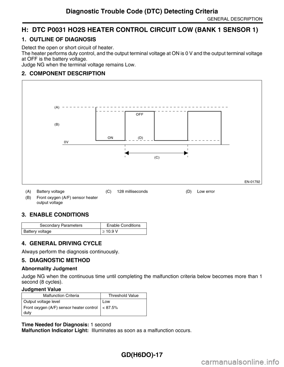
The heater performs duty control, and the output terminal voltage at ON is 0 V and the output terminal voltage
at OFF is the battery voltage.
Judge NG when the terminal voltage remains Low.
2. COMPONENT DESCRIPTION
3. ENABLE CONDITIONS
4. GENERAL DRIVING CYCLE
Always perform the diagnosis continuously.
5. DIAGNOSTIC METHOD
Abnormality Judgment
Judge NG when the continuous time until completing the malfunction criteria below becomes more than 1
second (8 cycles).
Time Needed for Diagnosis: 1 second
Malfunction Indicator Light: Illuminates as soon as a malfunction occurs.
(A) Battery voltage (C) 128 milliseconds (D) Low error
(B) Front oxygen (A/F) sensor heater
output voltage
Secondary Parameters Enable Conditions
Battery voltage≥ 10.9 V
Judgment Value
Malfunction Criteria Threshold Value
Output voltage level Low
Fr o nt ox yg en (A / F ) se ns or h ea t er co n tr o l
duty
< 87.5%
EN-01792
(C)
(A)
(B)
ON
OFF
0V(D)
Page 1633 of 2453
GD(H6DO)-21
Diagnostic Trouble Code (DTC) Detecting Criteria
GENERAL DESCRIPTION
J: DTC P0037 HO2S HEATER CONTROL CIRCUIT LOW (BANK 1 SENSOR 2)
1. OUTLINE OF DIAGNOSIS
Detect the rear oxygen sensor heater open or short circuit.
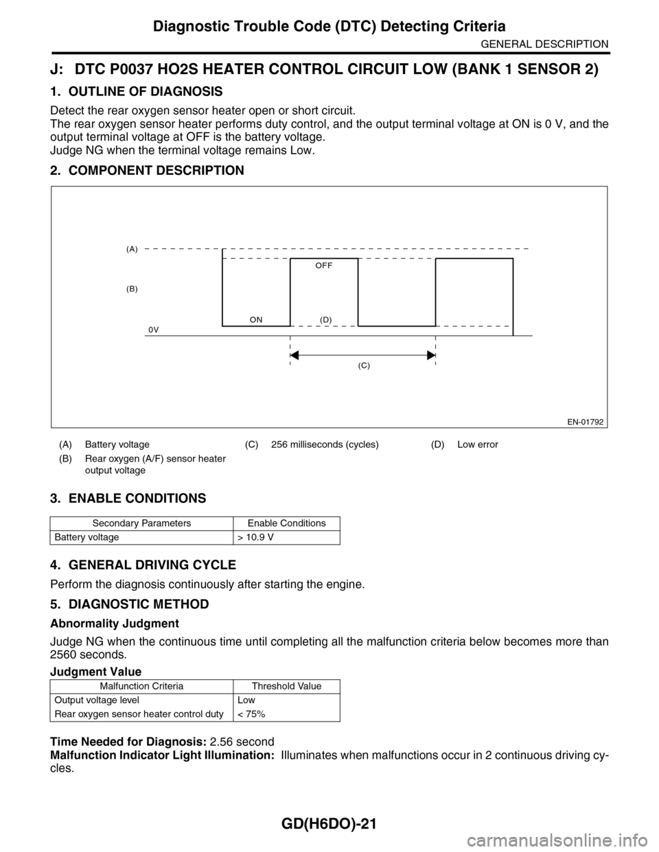
The rear oxygen sensor heater performs duty control, and the output terminal voltage at ON is 0 V, and the
output terminal voltage at OFF is the battery voltage.
Judge NG when the terminal voltage remains Low.
2. COMPONENT DESCRIPTION
3. ENABLE CONDITIONS
4. GENERAL DRIVING CYCLE
Perform the diagnosis continuously after starting the engine.
5. DIAGNOSTIC METHOD
Abnormality Judgment
Judge NG when the continuous time until completing all the malfunction criteria below becomes more than
2560 seconds.
Time Needed for Diagnosis: 2.56 second
Malfunction Indicator Light Illumination: Illuminates when malfunctions occur in 2 continuous driving cy-
cles.
(A) Battery voltage (C) 256 milliseconds (cycles) (D) Low error
(B) Rear oxygen (A/F) sensor heater
output voltage
Secondary Parameters Enable Conditions
Battery voltage > 10.9 V
Judgment Value
Malfunction Criteria Threshold Value
Output voltage level Low
Rear oxygen sensor heater control duty < 75%
EN-01792
(C)
(A)
(B)
ON
OFF
0V(D)