2009 SUBARU TRIBECA ignition
[x] Cancel search: ignitionPage 1306 of 2453
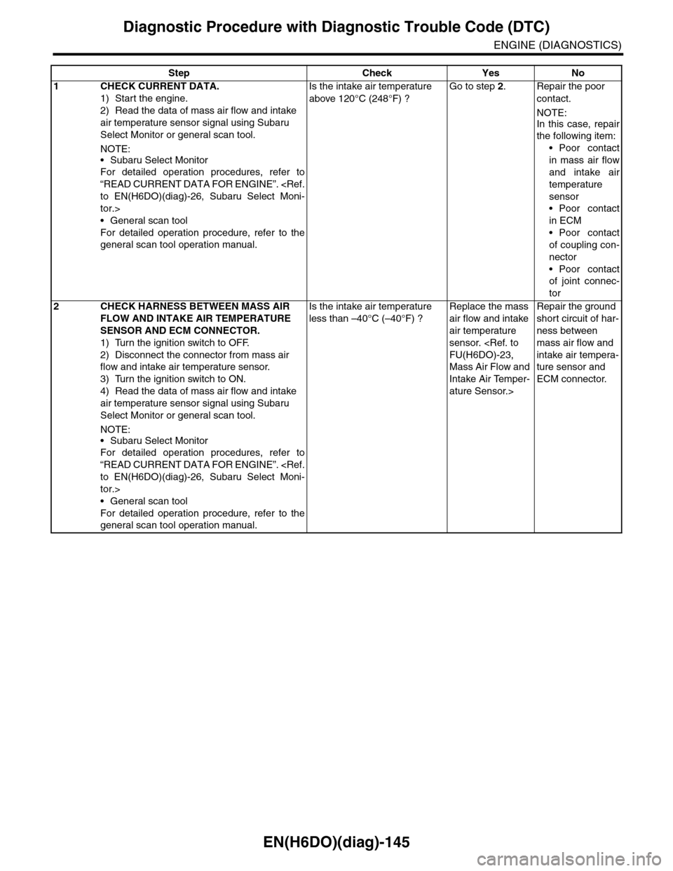
EN(H6DO)(diag)-145
Diagnostic Procedure with Diagnostic Trouble Code (DTC)
ENGINE (DIAGNOSTICS)
Step Check Yes No
1CHECK CURRENT DATA.
1) Start the engine.
2) Read the data of mass air flow and intake
air temperature sensor signal using Subaru
Select Monitor or general scan tool.
NOTE:
•Subaru Select Monitor
For detailed operation procedures, refer to
“READ CURRENT DATA FOR ENGINE”.
tor.>
•General scan tool
For detailed operation procedure, refer to the
general scan tool operation manual.
Is the intake air temperature
above 120°C (248°F) ?
Go to step 2.Repair the poor
contact.
NOTE:
In this case, repair
the following item:
•Poor contact
in mass air flow
and intake air
temperature
sensor
•Poor contact
in ECM
•Poor contact
of coupling con-
nector
•Poor contact
of joint connec-
tor
2CHECK HARNESS BETWEEN MASS AIR
FLOW AND INTAKE AIR TEMPERATURE
SENSOR AND ECM CONNECTOR.
1) Turn the ignition switch to OFF.
2) Disconnect the connector from mass air
flow and intake air temperature sensor.
3) Turn the ignition switch to ON.
4) Read the data of mass air flow and intake
air temperature sensor signal using Subaru
Select Monitor or general scan tool.
NOTE:
•Subaru Select Monitor
For detailed operation procedures, refer to
“READ CURRENT DATA FOR ENGINE”.
tor.>
•General scan tool
For detailed operation procedure, refer to the
general scan tool operation manual.
Is the intake air temperature
less than –40°C (–40°F) ?
Replace the mass
air flow and intake
air temperature
sensor.
Mass Air Flow and
Intake Air Temper-
ature Sensor.>
Repair the ground
short circuit of har-
ness between
mass air flow and
intake air tempera-
ture sensor and
ECM connector.
Page 1308 of 2453
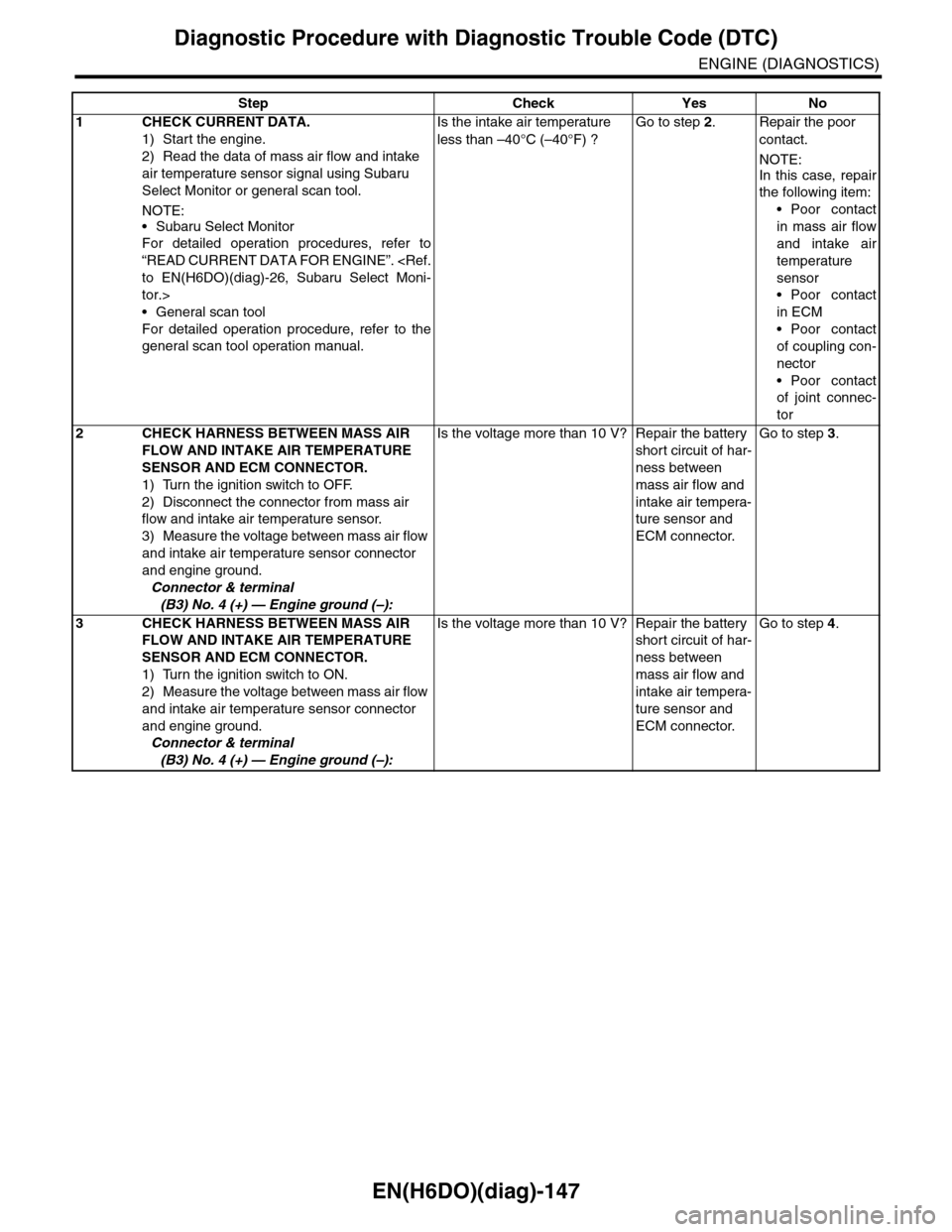
EN(H6DO)(diag)-147
Diagnostic Procedure with Diagnostic Trouble Code (DTC)
ENGINE (DIAGNOSTICS)
Step Check Yes No
1CHECK CURRENT DATA.
1) Start the engine.
2) Read the data of mass air flow and intake
air temperature sensor signal using Subaru
Select Monitor or general scan tool.
NOTE:
•Subaru Select Monitor
For detailed operation procedures, refer to
“READ CURRENT DATA FOR ENGINE”.
tor.>
•General scan tool
For detailed operation procedure, refer to the
general scan tool operation manual.
Is the intake air temperature
less than –40°C (–40°F) ?
Go to step 2.Repair the poor
contact.
NOTE:
In this case, repair
the following item:
•Poor contact
in mass air flow
and intake air
temperature
sensor
•Poor contact
in ECM
•Poor contact
of coupling con-
nector
•Poor contact
of joint connec-
tor
2CHECK HARNESS BETWEEN MASS AIR
FLOW AND INTAKE AIR TEMPERATURE
SENSOR AND ECM CONNECTOR.
1) Turn the ignition switch to OFF.
2) Disconnect the connector from mass air
flow and intake air temperature sensor.
3) Measure the voltage between mass air flow
and intake air temperature sensor connector
and engine ground.
Connector & terminal
(B3) No. 4 (+) — Engine ground (–):
Is the voltage more than 10 V? Repair the battery
short circuit of har-
ness between
mass air flow and
intake air tempera-
ture sensor and
ECM connector.
Go to step 3.
3CHECK HARNESS BETWEEN MASS AIR
FLOW AND INTAKE AIR TEMPERATURE
SENSOR AND ECM CONNECTOR.
1) Turn the ignition switch to ON.
2) Measure the voltage between mass air flow
and intake air temperature sensor connector
and engine ground.
Connector & terminal
(B3) No. 4 (+) — Engine ground (–):
Is the voltage more than 10 V? Repair the battery
short circuit of har-
ness between
mass air flow and
intake air tempera-
ture sensor and
ECM connector.
Go to step 4.
Page 1309 of 2453
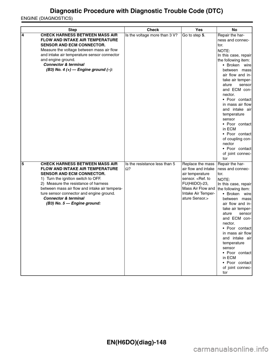
EN(H6DO)(diag)-148
Diagnostic Procedure with Diagnostic Trouble Code (DTC)
ENGINE (DIAGNOSTICS)
4CHECK HARNESS BETWEEN MASS AIR
FLOW AND INTAKE AIR TEMPERATURE
SENSOR AND ECM CONNECTOR.
Measure the voltage between mass air flow
and intake air temperature sensor connector
and engine ground.
Connector & terminal
(B3) No. 4 (+) — Engine ground (–):
Is the voltage more than 3 V? Go to step 5.Repair the har-
ness and connec-
tor.
NOTE:In this case, repair
the following item:
•Broken wire
between mass
air flow and in-
take air temper-
ature sensor
and ECM con-
nector.
•Poor contact
in mass air flow
and intake air
temperature
sensor
•Poor contact
in ECM
•Poor contact
of coupling con-
nector
•Poor contact
of joint connec-
tor
5CHECK HARNESS BETWEEN MASS AIR
FLOW AND INTAKE AIR TEMPERATURE
SENSOR AND ECM CONNECTOR.
1) Turn the ignition switch to OFF.
2) Measure the resistance of harness
between mass air flow and intake air tempera-
ture sensor connector and engine ground.
Connector & terminal
(B3) No. 5 — Engine ground:
Is the resistance less than 5
Ω?
Replace the mass
air flow and intake
air temperature
sensor.
Mass Air Flow and
Intake Air Temper-
ature Sensor.>
Repair the har-
ness and connec-
tor.
NOTE:In this case, repair
the following item:
•Broken wire
between mass
air flow and in-
take air temper-
ature sensor
and ECM con-
nector.
•Poor contact
in mass air flow
and intake air
temperature
sensor
•Poor contact
in ECM
•Poor contact
of joint connec-
tor
Step Check Yes No
Page 1311 of 2453
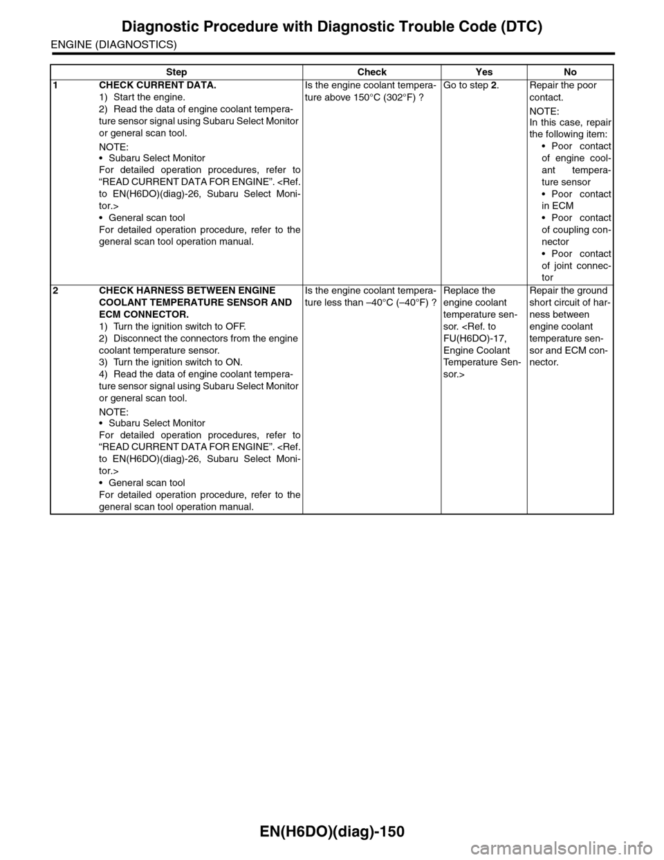
EN(H6DO)(diag)-150
Diagnostic Procedure with Diagnostic Trouble Code (DTC)
ENGINE (DIAGNOSTICS)
Step Check Yes No
1CHECK CURRENT DATA.
1) Start the engine.
2) Read the data of engine coolant tempera-
ture sensor signal using Subaru Select Monitor
or general scan tool.
NOTE:
•Subaru Select Monitor
For detailed operation procedures, refer to
“READ CURRENT DATA FOR ENGINE”.
tor.>
•General scan tool
For detailed operation procedure, refer to the
general scan tool operation manual.
Is the engine coolant tempera-
ture above 150°C (302°F) ?
Go to step 2.Repair the poor
contact.
NOTE:
In this case, repair
the following item:
•Poor contact
of engine cool-
ant tempera-
ture sensor
•Poor contact
in ECM
•Poor contact
of coupling con-
nector
•Poor contact
of joint connec-
tor
2CHECK HARNESS BETWEEN ENGINE
COOLANT TEMPERATURE SENSOR AND
ECM CONNECTOR.
1) Turn the ignition switch to OFF.
2) Disconnect the connectors from the engine
coolant temperature sensor.
3) Turn the ignition switch to ON.
4) Read the data of engine coolant tempera-
ture sensor signal using Subaru Select Monitor
or general scan tool.
NOTE:•Subaru Select Monitor
For detailed operation procedures, refer to
“READ CURRENT DATA FOR ENGINE”.
tor.>
•General scan tool
For detailed operation procedure, refer to the
general scan tool operation manual.
Is the engine coolant tempera-
ture less than –40°C (–40°F) ?
Replace the
engine coolant
temperature sen-
sor.
Engine Coolant
Te m p e r a t u r e S e n -
sor.>
Repair the ground
short circuit of har-
ness between
engine coolant
temperature sen-
sor and ECM con-
nector.
Page 1313 of 2453
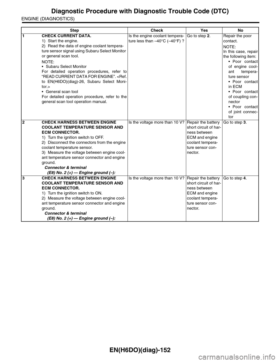
EN(H6DO)(diag)-152
Diagnostic Procedure with Diagnostic Trouble Code (DTC)
ENGINE (DIAGNOSTICS)
Step Check Yes No
1CHECK CURRENT DATA.
1) Start the engine.
2) Read the data of engine coolant tempera-
ture sensor signal using Subaru Select Monitor
or general scan tool.
NOTE:
•Subaru Select Monitor
For detailed operation procedures, refer to
“READ CURRENT DATA FOR ENGINE”.
tor.>
•General scan tool
For detailed operation procedure, refer to the
general scan tool operation manual.
Is the engine coolant tempera-
ture less than –40°C (–40°F) ?
Go to step 2.Repair the poor
contact.
NOTE:
In this case, repair
the following item:
•Poor contact
of engine cool-
ant tempera-
ture sensor
•Poor contact
in ECM
•Poor contact
of coupling con-
nector
•Poor contact
of joint connec-
tor
2CHECK HARNESS BETWEEN ENGINE
COOLANT TEMPERATURE SENSOR AND
ECM CONNECTOR.
1) Turn the ignition switch to OFF.
2) Disconnect the connectors from the engine
coolant temperature sensor.
3) Measure the voltage between engine cool-
ant temperature sensor connector and engine
ground.
Connector & terminal
(E8) No. 2 (+) — Engine ground (–):
Is the voltage more than 10 V? Repair the battery
short circuit of har-
ness between
ECM and engine
coolant tempera-
ture sensor con-
nector.
Go to step 3.
3CHECK HARNESS BETWEEN ENGINE
COOLANT TEMPERATURE SENSOR AND
ECM CONNECTOR.
1) Turn the ignition switch to ON.
2) Measure the voltage between engine cool-
ant temperature sensor connector and engine
ground.
Connector & terminal
(E8) No. 2 (+) — Engine ground (–):
Is the voltage more than 10 V? Repair the battery
short circuit of har-
ness between
ECM and engine
coolant tempera-
ture sensor con-
nector.
Go to step 4.
Page 1314 of 2453
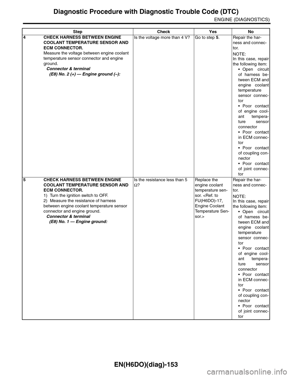
EN(H6DO)(diag)-153
Diagnostic Procedure with Diagnostic Trouble Code (DTC)
ENGINE (DIAGNOSTICS)
4CHECK HARNESS BETWEEN ENGINE
COOLANT TEMPERATURE SENSOR AND
ECM CONNECTOR.
Measure the voltage between engine coolant
temperature sensor connector and engine
ground.
Connector & terminal
(E8) No. 2 (+) — Engine ground (–):
Is the voltage more than 4 V? Go to step 5.Repair the har-
ness and connec-
tor.
NOTE:In this case, repair
the following item:
•Open circuit
of harness be-
tween ECM and
engine coolant
temperature
sensor connec-
tor
•Poor contact
of engine cool-
ant tempera-
ture sensor
connector
•Poor contact
in ECM connec-
tor
•Poor contact
of coupling con-
nector
•Poor contact
of joint connec-
tor
5CHECK HARNESS BETWEEN ENGINE
COOLANT TEMPERATURE SENSOR AND
ECM CONNECTOR.
1) Turn the ignition switch to OFF.
2) Measure the resistance of harness
between engine coolant temperature sensor
connector and engine ground.
Connector & terminal
(E8) No. 1 — Engine ground:
Is the resistance less than 5
Ω?
Replace the
engine coolant
temperature sen-
sor.
Engine Coolant
Te m p e r a t u r e S e n -
sor.>
Repair the har-
ness and connec-
tor.
NOTE:In this case, repair
the following item:
•Open circuit
of harness be-
tween ECM and
engine coolant
temperature
sensor connec-
tor
•Poor contact
of engine cool-
ant tempera-
ture sensor
connector
•Poor contact
in ECM connec-
tor
•Poor contact
of coupling con-
nector
•Poor contact
of joint connec-
tor
Step Check Yes No
Page 1317 of 2453
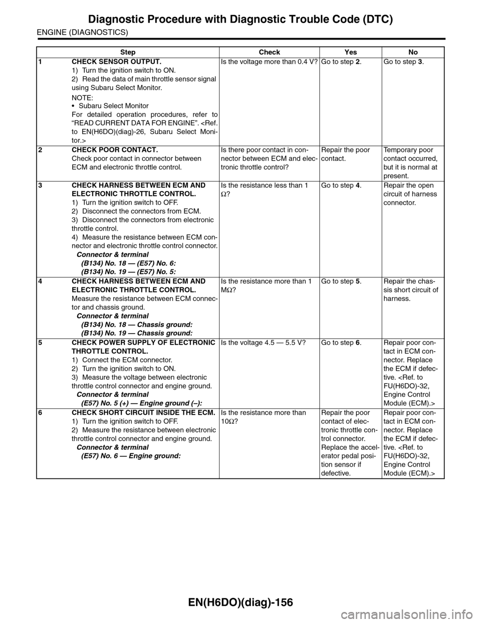
EN(H6DO)(diag)-156
Diagnostic Procedure with Diagnostic Trouble Code (DTC)
ENGINE (DIAGNOSTICS)
Step Check Yes No
1CHECK SENSOR OUTPUT.
1) Turn the ignition switch to ON.
2) Read the data of main throttle sensor signal
using Subaru Select Monitor.
NOTE:•Subaru Select Monitor
For detailed operation procedures, refer to
“READ CURRENT DATA FOR ENGINE”.
tor.>
Is the voltage more than 0.4 V? Go to step 2.Go to step 3.
2CHECK POOR CONTACT.
Check poor contact in connector between
ECM and electronic throttle control.
Is there poor contact in con-
nector between ECM and elec-
tronic throttle control?
Repair the poor
contact.
Te m p o r a r y p o o r
contact occurred,
but it is normal at
present.
3CHECK HARNESS BETWEEN ECM AND
ELECTRONIC THROTTLE CONTROL.
1) Turn the ignition switch to OFF.
2) Disconnect the connectors from ECM.
3) Disconnect the connectors from electronic
throttle control.
4) Measure the resistance between ECM con-
nector and electronic throttle control connector.
Connector & terminal
(B134) No. 18 — (E57) No. 6:
(B134) No. 19 — (E57) No. 5:
Is the resistance less than 1
Ω?
Go to step 4.Repair the open
circuit of harness
connector.
4CHECK HARNESS BETWEEN ECM AND
ELECTRONIC THROTTLE CONTROL.
Measure the resistance between ECM connec-
tor and chassis ground.
Connector & terminal
(B134) No. 18 — Chassis ground:
(B134) No. 19 — Chassis ground:
Is the resistance more than 1
MΩ?
Go to step 5.Repair the chas-
sis short circuit of
harness.
5CHECK POWER SUPPLY OF ELECTRONIC
THROTTLE CONTROL.
1) Connect the ECM connector.
2) Turn the ignition switch to ON.
3) Measure the voltage between electronic
throttle control connector and engine ground.
Connector & terminal
(E57) No. 5 (+) — Engine ground (–):
Is the voltage 4.5 — 5.5 V? Go to step 6.Repair poor con-
tact in ECM con-
nector. Replace
the ECM if defec-
tive.
Engine Control
Module (ECM).>
6CHECK SHORT CIRCUIT INSIDE THE ECM.
1) Turn the ignition switch to OFF.
2) Measure the resistance between electronic
throttle control connector and engine ground.
Connector & terminal
(E57) No. 6 — Engine ground:
Is the resistance more than
10Ω?
Repair the poor
contact of elec-
tronic throttle con-
trol connector.
Replace the accel-
erator pedal posi-
tion sensor if
defective.
Repair poor con-
tact in ECM con-
nector. Replace
the ECM if defec-
tive.
Engine Control
Module (ECM).>
Page 1320 of 2453
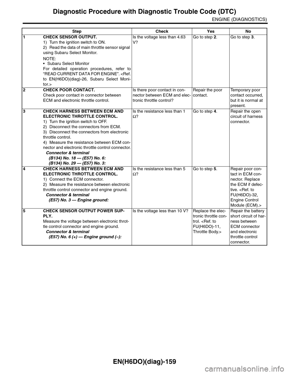
EN(H6DO)(diag)-159
Diagnostic Procedure with Diagnostic Trouble Code (DTC)
ENGINE (DIAGNOSTICS)
Step Check Yes No
1CHECK SENSOR OUTPUT.
1) Turn the ignition switch to ON.
2) Read the data of main throttle sensor signal
using Subaru Select Monitor.
NOTE:•Subaru Select Monitor
For detailed operation procedures, refer to
“READ CURRENT DATA FOR ENGINE”.
tor.>
Is the voltage less than 4.63
V?
Go to step 2.Go to step 3.
2CHECK POOR CONTACT.
Check poor contact in connector between
ECM and electronic throttle control.
Is there poor contact in con-
nector between ECM and elec-
tronic throttle control?
Repair the poor
contact.
Te m p o r a r y p o o r
contact occurred,
but it is normal at
present.
3CHECK HARNESS BETWEEN ECM AND
ELECTRONIC THROTTLE CONTROL.
1) Turn the ignition switch to OFF.
2) Disconnect the connectors from ECM.
3) Disconnect the connectors from electronic
throttle control.
4) Measure the resistance between ECM con-
nector and electronic throttle control connector.
Connector & terminal
(B134) No. 18 — (E57) No. 6:
(B134) No. 29 — (E57) No. 3:
Is the resistance less than 1
Ω?
Go to step 4.Repair the open
circuit of harness
connector.
4CHECK HARNESS BETWEEN ECM AND
ELECTRONIC THROTTLE CONTROL.
1) Connect the ECM connector.
2) Measure the resistance between electronic
throttle control connector and engine ground.
Connector & terminal
(E57) No. 3 — Engine ground:
Is the resistance less than 5
Ω?
Go to step 5.Repair poor con-
tact in ECM con-
nector. Replace
the ECM if defec-
tive.
Engine Control
Module (ECM).>
5CHECK SENSOR OUTPUT POWER SUP-
PLY.
Measure the voltage between electronic throt-
tle control connector and engine ground.
Connector & terminal
(E57) No. 6 (+) — Engine ground (–):
Is the voltage less than 10 V? Replace the elec-
tronic throttle con-
trol.
Throttle Body.>
Repair the battery
short circuit of har-
ness between
ECM connector
and electronic
throttle control
connector.