Page 155 of 2453

AB(diag)-131
Diagnostic Chart with Trouble Code
AIRBAG SYSTEM (DIAGNOSTICS)
AU:DTC 95 CURTAIN AIRBAG MODULE RH FAILURE
DTC DETECTING CONDITION:
•Curtain airbag harness (RH) is shorted to power supply.
•Airbag control module is faulty.
CAUTION:
•Before diagnosing the airbag system, be sure to turn the ignition switch to OFF, disconnect the
ground terminal from battery, and wait more than 20 seconds before starting to work.
•After replacing the airbag module, seat belt pretensioner, roll connector, control module and sen-
sor, reconnect each part and confirm that the warning light operates properly.
•When inspecting the airbag main harness, disconnect the airbag module connectors of driver's
and passenger's seats for safety reasons.
•When inspecting the airbag rear harness, disconnect the side airbag module connector, curtain
airbag module connector and seat belt pretensioner connector for safety reasons.
WIRING DIAGRAM:
AB-00671
AB18
AB33
AB40
12
65
AB34
2019418
3412
AB18AB33
12789101112
13141516171819
56
20
1234
AIRBAG CONTROL MODULE
INFLATOR(CURTAIN RH)
CURTAIN AIRBAGSENSOR RH
AB34
1234
Page 157 of 2453

AB(diag)-133
Diagnostic Chart with Trouble Code
AIRBAG SYSTEM (DIAGNOSTICS)
AV:DTC 96 CURTAIN AIRBAG MODULE LH FAILURE
DTC DETECTING CONDITION:
•Curtain airbag harness (LH) is shorted to power supply.
•Airbag control module is faulty.
CAUTION:
•Before diagnosing the airbag system, be sure to turn the ignition switch to OFF, disconnect the
ground terminal from battery, and wait more than 20 seconds before starting to work.
•After replacing the airbag module, seat belt pretensioner, roll connector, control module and sen-
sor, reconnect each part and confirm that the warning light operates properly.
•When inspecting the airbag main harness, disconnect the airbag module connectors of driver's
and passenger's seats for safety reasons.
•When inspecting the airbag rear harness, disconnect the side airbag module connector, curtain
airbag module connector and seat belt pretensioner connector for safety reasons.
WIRING DIAGRAM:
AB-00672
AB3212
1112
AB31
AB39
1511413
3412
AB31
12
AB17
AB17
789101112
13141516171819
56
20
1234
AIRBAG CONTROL MODULE
INFLATOR(CURTAIN LH)
CURTAIN AIRBAGSENSOR LH
AB32
1234
Page 287 of 2453
EI-45
Rear Quarter Trim
EXTERIOR/INTERIOR TRIM
19.Rear Quarter Trim
A: REMOVAL
1) Remove the third-row seats.
REMOVAL, Third-row Seats.>
2) Remove the rear door scuff plate.
REMOVAL, Side Trim.>
3) Remove the lower anchor cover.
4) Remove the luggage floor mat and utility box.
5) Remove the luggage floor end cover.
6) Remove the cover, and remove the bolts inside.
7) Remove the rear quarter lower trim.
8) Remove the rear quarter top trim.
9) Remove the lower anchor bolts of second-row
seat belts.
10) Remove the upper and lower anchor bolts of
third-row seat belts.
11) Remove the cover, and remove the bolts in-
side.
12) Remove the cap (A) on the upper side of pillar
trim, and remove the bolt inside.
EI-01344
EI-01345
EI-01346
EI-01347
EI-01353
EI-01348
EI-01349
EI-01377
Page 289 of 2453

EI-47
Floor Mat
EXTERIOR/INTERIOR TRIM
20.Floor Mat
A: REMOVAL
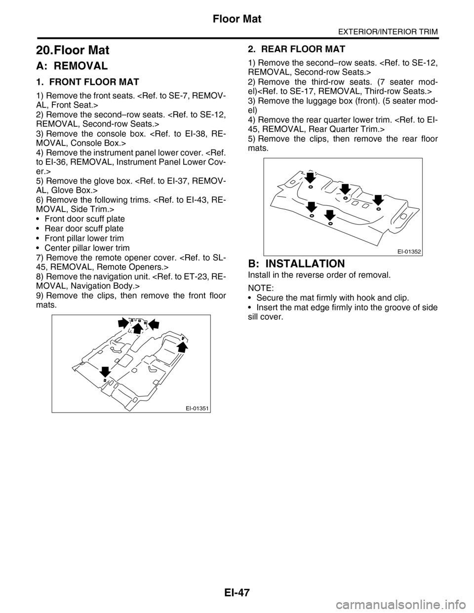
1. FRONT FLOOR MAT
1) Remove the front seats.
AL, Front Seat.>
2) Remove the second–row seats.
REMOVAL, Second-row Seats.>
3) Remove the console box.
MOVAL, Console Box.>
4) Remove the instrument panel lower cover.
to EI-36, REMOVAL, Instrument Panel Lower Cov-
er.>
5) Remove the glove box.
AL, Glove Box.>
6) Remove the following trims.
MOVAL, Side Trim.>
•Front door scuff plate
•Rear door scuff plate
•Front pillar lower trim
•Center pillar lower trim
7) Remove the remote opener cover.
45, REMOVAL, Remote Openers.>
8) Remove the navigation unit.
MOVAL, Navigation Body.>
9) Remove the clips, then remove the front floor
mats.
2. REAR FLOOR MAT
1) Remove the second–row seats.
REMOVAL, Second-row Seats.>
2) Remove the third-row seats. (7 seater mod-
el)
3) Remove the luggage box (front). (5 seater mod-
el)
4) Remove the rear quarter lower trim.
45, REMOVAL, Rear Quarter Trim.>
5) Remove the clips, then remove the rear floor
mats.
B: INSTALLATION
Install in the reverse order of removal.
NOTE:
•Secure the mat firmly with hook and clip.
•Insert the mat edge firmly into the groove of side
sill cover.
EI-01351
EI-01352
Page 373 of 2453
AC-47
Heater Duct
HVAC SYSTEM (HEATER, VENTILATOR AND A/C)
26.Heater Duct
A: REMOVAL
1. FRONT HEATER DUCT
1) Remove the instrument panel lower cover.
to EI-36, REMOVAL, Instrument Panel Lower Cov-
er.>
2) Remove the catch and detach the front heater
duct (A).
2. REAR HEATER DUCT
1) Remove the heater cooling unit.
REMOVAL, Heater and Cooling Unit.>
2) Remove the front seats.
AL, Front Seat.>
3) Remove the front side sill cover.
4) Pull off the floor mat to remove the rear center
heater duct (A) and rear heater duct LH, RH (B).
B: INSTALLATION
Install in the reverse order of removal.
AC-01349
(A)
AC-01350
(A)
(B)
Page 466 of 2453

LAN(diag)-10
Control Module I/O Signal
LAN SYSTEM (DIAGNOSTICS)
Manual switch (UNLOCK) i84 A29 Less than 1 ΩDoor unlock switch ON
Door lock power supply i84 A34 10 — 13 V Always
All door lock output i84 A7 10 — 13 V Manual lock switch, door key switch ON
Driver’s door UNLOCK
outputi84 A23 10 — 13 V Driver’s seat unlock signal ON
All door UNLOCK output i84 A8 10 — 13 V ALL door unlock signals ON
Rear gate UNLOCK out-
puti84 A22 10 — 13 VWhen rear gate release switch ON with
all seats unlocked
Rear gate release switch B281 C22 0 V Rear gate release switch ON
Key/shift lock power sup-
plyB281 C1 10 — 13 V Always
Shift lock output B280 B6 10 — 13 VIgnition switch ON, shift position “P”
range, foot brake ON (Only AT)
Key locking output B280 B5 10 — 13 VOther than “P” range, ignition switch
ON
Wiper deicer switch i84 A14 0 V Wiper deicer switch ON
Wiper deicer relay output B280 B14 0 V Wiper deicer relay ON
Rear defogger switch i84 A28 0 V Rear defogger switch ON
Rear defogger relay out-
putB281 B16 0 V Rear defogger relay ON
Shift switch (ON) B281 C26 0 V At Manual mode
Shift switch (UP) B281 C15 0 V At Manual mode UP
Shift switch (DOWN) B281 C25 0 V At Manual mode DOWN
Shift button switch B281 C24 0 VWhen shift lever release button is oper-
ated
P range switch B281 C13 0 V Shift range P position
Impact sensor B281 C5 8 V or moreImpact sensor ON (Model with impact
sensor)
Fuel level sensor B281 C19 0 — 102.3 Ω
Resistance differs according to the fuel
level (displays resistance combining
level gauge main and sub)
Ambient temperature sen-
sor
B281 C3 0.5 — 4.5 V SIG
B281 C10 0 V GND
Seat belt switch (driver’s
seat)i84 A4 0 V When driver’s seat belt is worn
Seat belt switch (Passen-
ger’s seat)i84 A13 0 V When passenger’s seat belt is worn
Seat belt warning light
(driver’s seat)i84 A20 0 V When driver’s seat belt is worn
Seat belt warning light
(Passenger’s seat)B280 C27 0 V When passenger’s seat belt is worn
Rear wiper switch (ON) B281 C6 0 V Rear wiper switch ON
Rear wiper switch (INT) B281 C18 0 V Rear wiper switch ON
Rear washer switch B281 C27 0 V Rear washer switch ON
Rear wiper power supply B280 B21 10 — 13 V Ignition switch ON
Rear wiper ON output B280 B1 10 — 13 V Rear wiper switch ON
Rear wiper return B280B8 0 VAt wiper reversingB1 — B8 0 V
Room lamp output B280 B3 0 VWhen LOCK, UNLOCK with keyless
entry
Map lamp output B280D2 0 V When using map lamp
D9 0 V When using map lamp
DescriptionConnec-
tor No.
Te r m i n a l
No.
Signal (V)
NoteIgnition switch ON
(Engine OFF)
Page 609 of 2453

SB-12
Second Seat Belt
SEAT BELT SYSTEM
6. Second Seat Belt
A: REMOVAL
1. OUTER SEAT BELT RH ASSEMBLY AND
LH ASSEMBLY
1) Remove the second row seats.
REMOVAL, Second-row Seats.>
2) Remove the third-row seats.
REMOVAL, Third-row Seats.>
3) Remove the rear quarter trim.
REMOVAL, Rear Quarter Trim.>
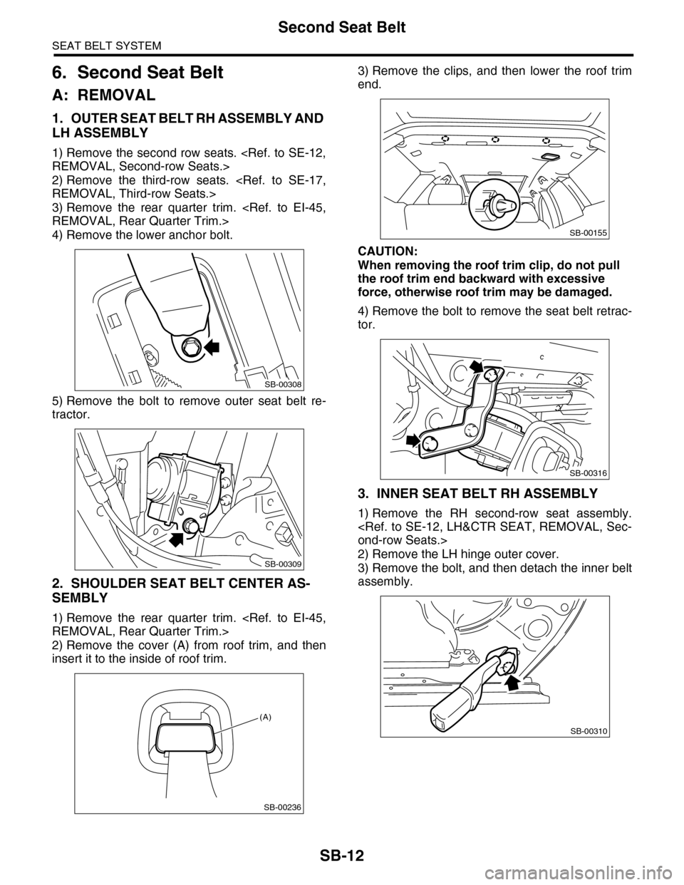
4) Remove the lower anchor bolt.
5) Remove the bolt to remove outer seat belt re-
tractor.
2. SHOULDER SEAT BELT CENTER AS-
SEMBLY
1) Remove the rear quarter trim.
REMOVAL, Rear Quarter Trim.>
2) Remove the cover (A) from roof trim, and then
insert it to the inside of roof trim.
3) Remove the clips, and then lower the roof trim
end.
CAUTION:
When removing the roof trim clip, do not pull
the roof trim end backward with excessive
force, otherwise roof trim may be damaged.
4) Remove the bolt to remove the seat belt retrac-
tor.
3. INNER SEAT BELT RH ASSEMBLY
1) Remove the RH second-row seat assembly.
ond-row Seats.>
2) Remove the LH hinge outer cover.
3) Remove the bolt, and then detach the inner belt
assembly.
SB-00308
SB-00309
SB-00236
(A)
SB-00155
SB-00316
SB-00310
Page 610 of 2453
SB-13
Second Seat Belt
SEAT BELT SYSTEM
4. SHOULDER SEAT BELT CENTER
BUCKLE
1) Remove the LH second-row seat assembly.
ond-row Seats.>
2) Remove the RH hinge outer cover.
3) Remove the bolt, and then remove the shoulder
seat belt center buckle.
5. INNER SEAT BELT LH ASSEMBLY
1) Remove the LH second-row seat assembly.
ond-row Seats.>
2) Remove the bolt from the back of the seat cush-
ion, and then detach the inner belt assembly.
B: INSTALLATION
Install in the reverse order of removal.
CAUTION:
When installing, be careful of the routing of the
seatbelt, and make sure that the belt is not
twisted.
C: INSPECTION
Check for the following, and replace with new parts
if necessary.
•Seat belt is slackened, bent or worn. Seat belt is
abnormally wound or extended.
•Inner belt is deformed or damaged.
•Seat belt buckle cannot be engaged properly.
SB-00311
SB-00312