Page 627 of 2453
SE-17
Third-row Seats
SEATS
4. Third-row Seats
A: REMOVAL
1) Lift up the front side of the 3rd seat cushion and
then remove the hooks.
2) Lift up the 3rd seat cushion and remove the seat
cushion by pushing it backward to detach the hook.
3) Remove the eight bolts securing the 3rd seat
back.
4) Remove the 3rd seat.
B: INSTALLATION
Install in the reverse order of removal.
Tightening torque:
Refer to “COMPONENT” of “General Descrip-
tion”.
Description.>
C: DISASSEMBLY
1) Remove the 3rd seat.
AL, Third-row Seats.>
2) Remove the headrest.
3) Pull out the seat belt tray.
4) Remove the hog rings (A) on the rear side of
seat cushion.
5) Remove the hog rings (A) on the front side of
seat cushion.
6) Remove the two screws securing the hinge lever
assembly.
7) Disconnect the wire connected to the hinge lever
assembly.
8) Remove the seat back cover.
SE-00621
SE-00622
SE-00623: (A)
SE-00624: (A)
SE-00625
SE-00626
Page 628 of 2453

SE-18
Third-row Seats
SEATS
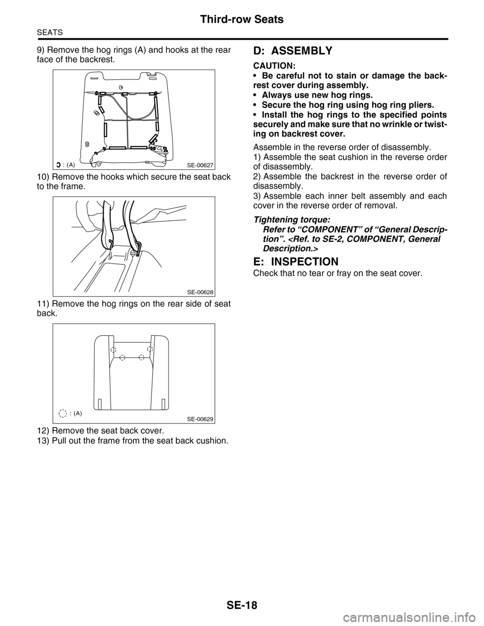
9) Remove the hog rings (A) and hooks at the rear
face of the backrest.
10) Remove the hooks which secure the seat back
to the frame.
11) Remove the hog rings on the rear side of seat
back.
12) Remove the seat back cover.
13) Pull out the frame from the seat back cushion.
D: ASSEMBLY
CAUTION:
•Be careful not to stain or damage the back-
rest cover during assembly.
•Always use new hog rings.
•Secure the hog ring using hog ring pliers.
•Install the hog rings to the specified points
securely and make sure that no wrinkle or twist-
ing on backrest cover.
Assemble in the reverse order of disassembly.
1) Assemble the seat cushion in the reverse order
of disassembly.
2) Assemble the backrest in the reverse order of
disassembly.
3) Assemble each inner belt assembly and each
cover in the reverse order of removal.
Tightening torque:
Refer to “COMPONENT” of “General Descrip-
tion”.
Description.>
E: INSPECTION
Check that no tear or fray on the seat cover.
: (A)SE-00627
SE-00628
SE-00629: (A)
Page 629 of 2453
SE-19
Seat Heater System
SEATS
5. Seat Heater System
A: REMOVAL
1. SEAT HEATER UNIT
1) Remove the front seats.
AL, Front Seat.>
2) Remove the backrest cover of front seat and
seat cushion cover.
BLY, Front Seat.>
3) Remove the hog rings, and then remove the seat
heater unit.
2. SEAT HEATER SWITCH
The seat heater switch is built into the control pan-
el.
B: INSTALLATION
Install in the reverse order of removal.
SE-00082
Page 630 of 2453
SE-20
Seat Heater System
SEATS
Page 674 of 2453

SL-45
Remote Openers
SECURITY AND LOCKS
16.Remote Openers
A: REMOVAL
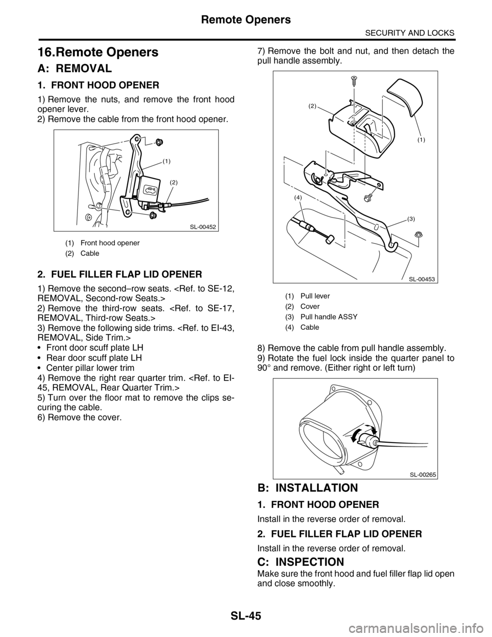
1. FRONT HOOD OPENER
1) Remove the nuts, and remove the front hood
opener lever.
2) Remove the cable from the front hood opener.
2. FUEL FILLER FLAP LID OPENER
1) Remove the second–row seats.
REMOVAL, Second-row Seats.>
2) Remove the third-row seats.
REMOVAL, Third-row Seats.>
3) Remove the following side trims.
REMOVAL, Side Trim.>
•Front door scuff plate LH
•Rear door scuff plate LH
•Center pillar lower trim
4) Remove the right rear quarter trim.
45, REMOVAL, Rear Quarter Trim.>
5) Turn over the floor mat to remove the clips se-
curing the cable.
6) Remove the cover.
7) Remove the bolt and nut, and then detach the
pull handle assembly.
8) Remove the cable from pull handle assembly.
9) Rotate the fuel lock inside the quarter panel to
90° and remove. (Either right or left turn)
B: INSTALLATION
1. FRONT HOOD OPENER
Install in the reverse order of removal.
2. FUEL FILLER FLAP LID OPENER
Install in the reverse order of removal.
C: INSPECTION
Make sure the front hood and fuel filler flap lid open
and close smoothly.
(1) Front hood opener
(2) Cable
SL-00452
(2)
(1)
(1) Pull lever
(2) Cover
(3) Pull handle ASSY
(4) Cable
SL-00453
(3)
(2)
(4)
(1)
SL-00265
Page 795 of 2453
DI-11
General Description
DIFFERENTIALS
2. GENERAL TOOL
498447100 INSTALLER Used for installing the oil seal.
399520105 SEATS • Used for removing the side bearing cone.
•Used with PULLER SET (899524100).
TOOL NAME REMARKS
Tr a n s m i s s i o n j a c k U s e d f o r a s s e m b l y / d i s a s s e m b l y o f t h e r e a r d i f f e r e n t i a l .
Puller Used for removing the side bearing retainer.
Thickness gauge Used for measuring clearance.
Hexagon wrench Used for installing and removing the filler and drain plug.
Tire lever Used for removing the front drive shaft.
ILLUSTRATION TOOL NUMBER DESCRIPTION REMARKS
ST-498447100
ST-399520105
Page 802 of 2453
DI-18
Rear Differential (VA–type)
DIFFERENTIALS
9) Remove the bearing race from holder RH and
LH with ST and press.
ST 18758AA000 PULLER
NOTE:
•Make sure the bolt of puller turn manually.
•Set the puller so that its claws catch the groove of
holder.
10) Remove the oil seal from holder RH and LH us-
ing screwdriver.
NOTE:
Perform this operation only when changing oil seal.
11) Extract the bearing cone with ST1, ST2 and
ST3
NOTE:
•Do not attempt to disassemble the parts unless
necessary.
•Never mix up the RH and LH bearing races and
cones.
ST1 498077000 REMOVER
ST2 399520105 SEATS
ST3 899864100 REMOVER
12) Remove the hypoid driven gear by loosening
hypoid driven gear bolts.
13) Remove the self-locking nut while holding the
companion flange with ST.
ST 498427200 FLANGE WRENCH
(A) Groove
(B) Claw
(A) Holder
ST
DI-00367
ST
(A)
(B)
(A)
ST
DI-00368
DI-00369
DI-00370
ST1
ST2
ST3
DI-00371
DI-00372
ST
Page 868 of 2453

FS-20
Front Strut
FRONT SUSPENSION
C: DISASSEMBLY
1) Using a coil spring compressor, compress the
coil spring.
2) Using the ST, remove the self–locking nut.
ST 20399AG000 STRUT MOUNT SOCKET
3) Remove the strut mount, spacer and upper
spring seat from strut.
4) Gradually decrease the compression force of
compressor, and remove the coil spring.
5) Remove the dust cover and helper spring.
D: ASSEMBLY
1) Before installing the coil spring, strut mount, etc.
on strut, check for the presence of air in the damp-
ening force generating mechanism of the strut
since air prevents proper dampening force produc-
tion.
2) Checking for presence of air
(1) Place the strut vertically with the piston rod
facing up.
(2) Move the piston rod to the center of its entire
stroke.
(3) While holding the piston rod end with fin-
gers, move the rod up and down.
(4) If the piston rod moves more than 10 mm
(0.39 in) in the former step, purge air from the
strut.
3) Air purging procedure
(1) Place the strut vertically with the piston rod
facing up.
(2) Fully extend the piston rod.
(3) With the piston rod fully extended, place the
piston rod side down. The strut must stand ver-
tically.
(4) Fully retract the piston rod.
(5) Repeat 3 or 4 times from the step (1).
NOTE:
After purging air from the strut, be sure to place the
strut with the piston rod facing up. If the strut is laid
down for any reason, check for the entry of air in ac-
cordance with “Checking for presence of air”
4) Using a coil spring compressor, compress the
coil spring.
NOTE:
Make sure that the vertical install direction of the
coil spring is as shown in the figure.
5) Set the coil spring correctly so that its end face
seats well in the spring seat as shown in the figure.
6) Install the helper and dust cover to the piston
rod.
FS-00040
FS-00041
ST
(1) Place the flat end on the top side.
(2) Identification paint
(1) Coil spring end face
FS-00216
(2)
(1)
FS-00043
(1)