2009 SUBARU TRIBECA rear wiper
[x] Cancel search: rear wiperPage 714 of 2453
WW-19
Rear Wiper Motor
WIPER AND WASHER SYSTEMS
11.Rear Wiper Motor
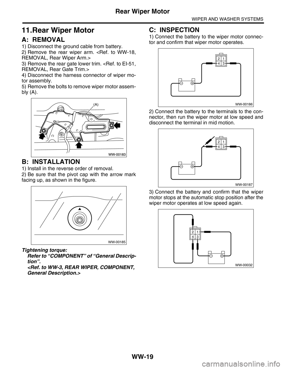
A: REMOVAL
1) Disconnect the ground cable from battery.
2) Remove the rear wiper arm.
3) Remove the rear gate lower trim.
4) Disconnect the harness connector of wiper mo-
tor assembly.
5) Remove the bolts to remove wiper motor assem-
bly (A).
B: INSTALLATION
1) Install in the reverse order of removal.
2) Be sure that the pivot cap with the arrow mark
facing up, as shown in the figure.
Tightening torque:
Refer to “COMPONENT” of “General Descrip-
tion”.
C: INSPECTION
1) Connect the battery to the wiper motor connec-
tor and confirm that wiper motor operates.
2) Connect the battery to the terminals to the con-
nector, then run the wiper motor at low speed and
disconnect the terminal in mid motion.
3) Connect the battery and confirm that the wiper
motor stops at the automatic stop position after the
wiper motor operates at low speed again.
WW-00185
WW-00186
21
43
WW-00187
21
43
WW-00032
21
43
Page 715 of 2453
WW-20
Rear Washer
WIPER AND WASHER SYSTEMS
12.Rear Washer
A: REMOVAL
1) Detach the roof spoiler.
2) Remove the washer hose from washer nozzle.
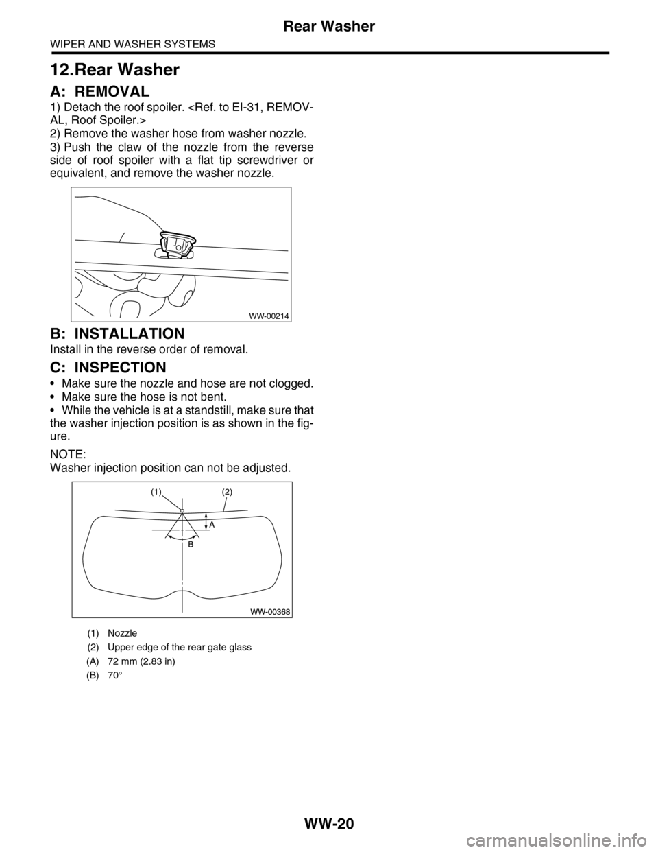
3) Push the claw of the nozzle from the reverse
side of roof spoiler with a flat tip screwdriver or
equivalent, and remove the washer nozzle.
B: INSTALLATION
Install in the reverse order of removal.
C: INSPECTION
•Make sure the nozzle and hose are not clogged.
•Make sure the hose is not bent.
•While the vehicle is at a standstill, make sure that
the washer injection position is as shown in the fig-
ure.
NOTE:
Washer injection position can not be adjusted.
(1) Nozzle
(2) Upper edge of the rear gate glass
(A) 72 mm (2.83 in)
(B) 70°
WW-00214
Page 1164 of 2453
EN(H6DO)(diag)-3
Check List for Interview
ENGINE (DIAGNOSTICS)
2. Check List for Interview
A: CHECK
1. CHECK LIST No. 1
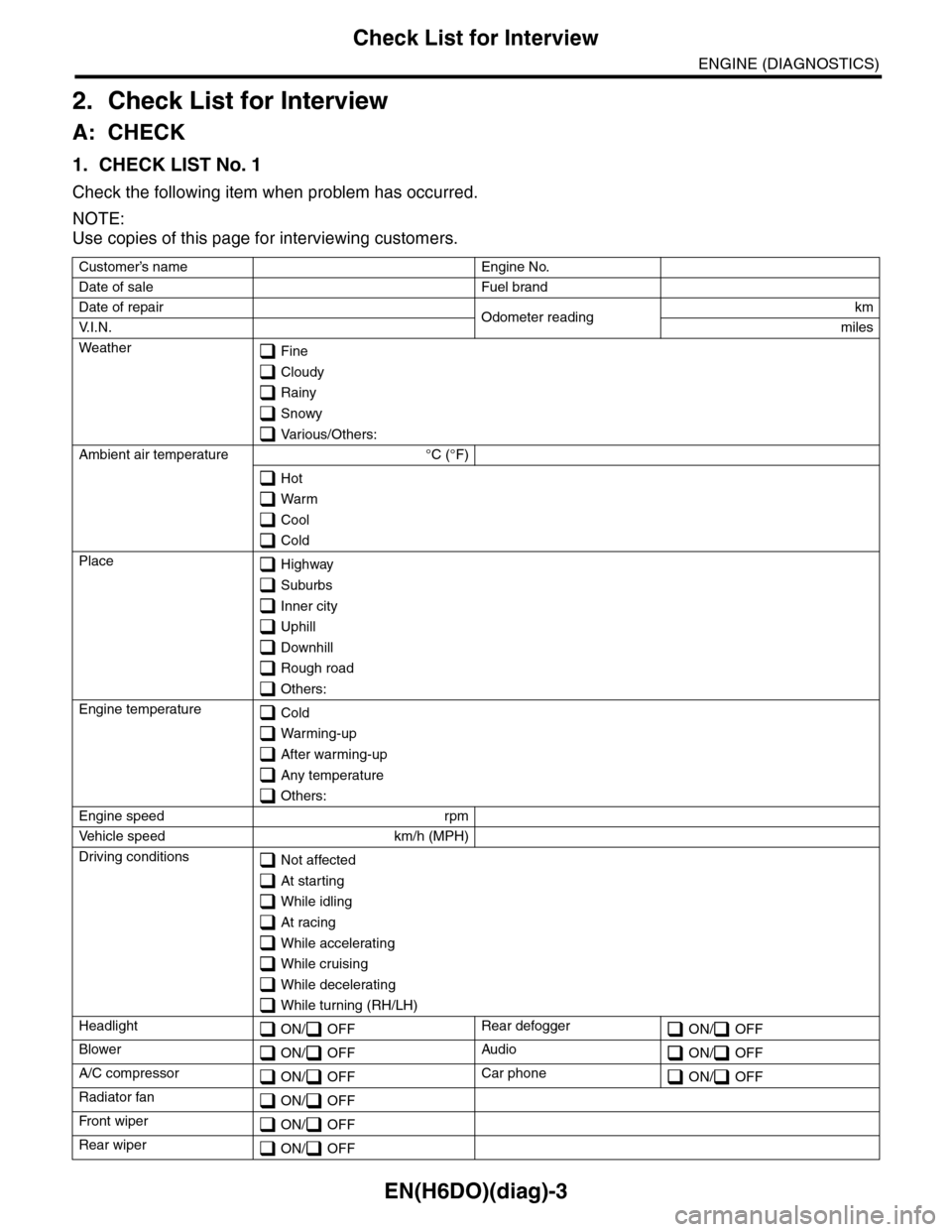
Check the following item when problem has occurred.
NOTE:
Use copies of this page for interviewing customers.
Customer’s name Engine No.
Date of sale Fuel brand
Date of repair Odometer readingkm
V. I . N . miles
Weather Fine
Cloudy
Rainy
Snowy
Various/Others:
Ambient air temperature °C (°F)
Hot
Warm
Cool
Cold
Place Highway
Suburbs
Inner city
Uphill
Downhill
Rough road
Others:
Engine temperature Cold
Warming-up
After warming-up
Any temperature
Others:
Engine speed rpm
Ve h i c l e s p e e d k m / h ( M P H )
Driving conditions Not affected
At starting
While idling
At racing
While accelerating
While cruising
While decelerating
While turning (RH/LH)
Headlight ON/ OFFRear defogger ON/ OFF
Blower ON/ OFFAudio ON/ OFF
A/C compressor ON/ OFFCar phone ON/ OFF
Radiator fan ON/ OFF
Fr o nt wi pe r ON/ OFF
Rear wiper ON/ OFF
Page 1189 of 2453
EN(H6DO)(diag)-28
Subaru Select Monitor
ENGINE (DIAGNOSTICS)
Fr o nt ox yg e n ( A / F) s en so r r es is t an ce val ue 2 A / F s en s or r e si st a nc e val u e 2Ω31 Ω
Fr o nt ox yg e n ( A / F) s en so r ou t p ut la m bd a 1 A / F s en s or o ut p ut l am bd a 1 — 1 . 00
Fr o nt ox yg e n ( A / F) s en so r ou t p ut la m bd a 2 A / F s en s or o ut p ut l am bd a 2 — 1 . 00
Fuel tank pressure signal Fuel Tank PressuremmHg, kPa,
inHg or psig
+8.8 mmHg, +1.2 kPa,
+0.4 inHg or +0.17 psig
Fuel temperature signal Fuel Temp. °C or °F +28°C or +82°F
A/F compensation 3 A/F Compensation 3 % –0.16%
A/F learning 3 A/F learning 3 % 0.0%
Throttle motor duty Throttle motor duty % –27%
Throttle power supply voltage Throttle power supply voltage V (Battery voltage)
Sub throttle sensor voltage Sub throttle sensor voltage V 1.50 V
Main throttle sensor voltage Main throttle sensor voltage V 0.64 V
Sub acceleration sensor voltage Sub acceleration sensor voltage V 0.7 V
Main acceleration sensor voltage Main acceleration sensor voltage V 0.7 V
Memory vehicle speed Memory vehicle speed km/h or MPH 0 km/h or 0 MPH
A/F compensation 4 A/F Compensation 4 % 0.31%
A/F learning 4 A/F learning 4 % 0.0%
Fuel level sensor resistance Fuel level resistanceΩ4 — 96 Ω
Oil temperature Oil Temperature °C≥ 85°C (After engine is
warmed-up.)
Oil switching solenoid valve duty R OSV duty R % 17.3%
Oil switching solenoid valve duty L OSV duty L % 17.3%
Oil switching solenoid valve current R OSV current R mA 192 mA
Oil switching solenoid valve current L OSV current L mA 192 mA
Va r i a b l e va l v e l i f t m o d e V V L L i f t M o d e — 1
#1 cylinder roughness monitor #1 cylinder roughness monitor — 0
#2 cylinder roughness monitor #2 cylinder roughness monitor — 0
#3 cylinder roughness monitor #3 cylinder roughness monitor — 0
#4 cylinder roughness monitor #4 cylinder roughness monitor — 0
#5 cylinder roughness monitor #5 cylinder roughness monitor — 0
#6 cylinder roughness monitor #6 cylinder roughness monitor — 0
Te s t m o d e t e r m i n a l Te s t m o d e t e r m i n a l — U c h e c k
Neutral position switch signal Neutral SW — Neutral
Idle switch signal Soft idle SW — In idle
Ignition switch signal Ignition SW — ON input
Pow er s te e r in g sw it c h s ig n al Powe r st ee r i ng S W i n pu t si gn a l — O FF i np u t ( w h e n OF F )
Air conditioning switch signal A/C SW — OFF input (when OFF)
Starter switch signal Starter SW — OFF input
Fr o nt ox yg e n mo n it o r 1 Fr o n t oxy ge n m on i to r 1 — Ri ch
Fr o nt ox yg e n mo n it o r 2 Fr o n t oxy ge n m on i to r 2 — Ri ch
Knocking signal Knock signal — OFF
Crankshaft position sensor signal Crankshaft angle signal — Yes
Camshaft position sensor signal Camshaft angle signal — Yes
Drain valve signal Vent. Solenoid Valve — OFF output (when OFF)
Rear defogger switch signal Rear defogger SW — OFF input (when OFF)
Blower fan switch signal Blower fan SW — OFF input (when OFF)
Light switch signal Light SW — OFF input (when OFF)
Wiper switch signal Wiper SW — OFF input (when OFF)
A/C middle pressure switch signal A/C middle pressure SW — OFF input
A/C compressor relay signal A/C compressor relay output — OFF output
AT c o o r d i n a t e r e t a r d a n g l e d e m a n d s i g n a lAT c o o r d i n a t e r e t a r d a n g l e
demand—Yes
Description Display Unit of measure Note (at idling)
Page 1193 of 2453
![SUBARU TRIBECA 2009 1.G Service Workshop Manual EN(H6DO)(diag)-32
Subaru Select Monitor
ENGINE (DIAGNOSTICS)
7. LED OPERATION MODE FOR ENGINE
1) On the «Main Menu» display screen, select the {Each System Check} and press the [YES] key.
2) On the SUBARU TRIBECA 2009 1.G Service Workshop Manual EN(H6DO)(diag)-32
Subaru Select Monitor
ENGINE (DIAGNOSTICS)
7. LED OPERATION MODE FOR ENGINE
1) On the «Main Menu» display screen, select the {Each System Check} and press the [YES] key.
2) On the](/manual-img/17/7322/w960_7322-1192.png)
EN(H6DO)(diag)-32
Subaru Select Monitor
ENGINE (DIAGNOSTICS)
7. LED OPERATION MODE FOR ENGINE
1) On the «Main Menu» display screen, select the {Each System Check} and press the [YES] key.
2) On the «System Selection Menu» display screen, select the {Engine} and press the [YES] key.
3) Press the [YES] key after the information of engine type has been displayed.
4) On the «Engine Diagnosis» display screen, select the {Current Data Display/Save}, and then press the
[YES] key.
5) On the «Data Display» screen, select the {Data LED Display} and press the [YES] key.
6) Using the scroll key, scroll the display screen up or down until the desired data is shown.
•A list of the support data is shown in the following table.
NOTE:
For detailed operation procedure, refer to the “SUBARU SELECT MONITOR OPERATION MANUAL”.
Description Display Message When LED “ON” required
Te s t m o d e s i g n a l Te s t m o d e t e r m i n a l D c h e c k / U c h e c k D c h e c k
Neutral position switch signal Neutral SW Neutral/Other than neutral Neutral
Idle switch signal Soft idle SW Idle/Other than idle In idle
Ignition switch signal Ignition SW ON Input/OFF Input ON input
Pow er s te e r in g sw it c h s ig n al Pow er s te e r in g S W ON I np u t/ O FF I np u t ON i np ut
Air conditioning switch signal A/C SW ON Input/OFF Input ON input
Starter switch signal Starter SW ON Input/OFF Input ON input
Fr o nt ox yg e n mo n it o r 1 Ft O 2 mo n it o r 1 Le a n/ Ri ch Ric h
Fr o nt ox yg e n mo n it o r 2 Ft O 2 mo n it o r 2 Le a n/ Ri ch Ric h
Knocking signal Knock signal Yes/No Yes
Crankshaft position sensor signal Crankshaft angle signal Yes/No Yes
Camshaft position sensor signal Camshaft angle signal Yes/No Yes
Rear defogger switch signal Rear defogger SW ON Input/OFF Input ON input
Blower fan switch signal Blower fan SW ON Input/OFF Input ON input
Light switch signal Light SW ON Input/OFF Input ON input
Wiper switch signal Wiper SW ON Input/OFF Input ON input
A/C middle pressure switch signal A/C middle pressure SW ON Input/OFF Input ON input
Air conditioner compressor relay sig-
nalCompressor relay ON output/OFF output ON output
Drain valve signal Vent. Solenoid Valve ON or OFF When drain valve is ON.
AT r e t a r d a n g l e d e m a n d s i g n a l AT r e t a r d a n g l e d e m a n d Ye s / N o Ye s
AT f u e l c u t s i g n a l AT f u e l c u t Ye s / N o Ye s
VDC torque down prohibition output Torque down output ON/OFF Prohibition
VDC torque down demand Torque down demand Yes/No Yes
AT c o o r d i n a t e p e r m i s s i o n s i g n a lAT c o o r d i n a t e p e r m i s s i o n
signalON/OFF Permission
Electronic throttle control motor relay
signalETC motor relay ON/OFF ON
Stop light switch signal Stop SW ON Input/OFF Input ON input
SET/COAST switch signal SET/CST SW ON Input/OFF Input ON input
RESUME/ACCEL switch signal RES/ACC SW ON Input/OFF Input ON input
Brake switch signal Brake SW ON Input/OFF Input ON input
Main switch signal Main SW ON Input/OFF Input ON input
Body integrated unit data reception Body Int. Unit Data Yes/No Yes
Body integrated unit counter update Body Int. Unit Count Yes/No Yes
Cruise control cancel switch signal CC Cancel SW ON Input/OFF Input ON input
Va r i a b l e va l v e l i f t d i a g n o s i s o i l p r e s -
sure switch signal 1Oil Temperature SW1 ON/OFF ON
Va r i a b l e va l v e l i f t d i a g n o s i s o i l p r e s -
sure switch signal 2Oil Temperature SW2 ON/OFF ON
Page 2304 of 2453
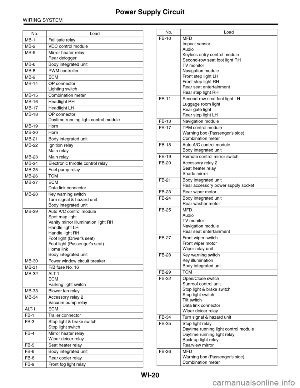
WI-20
Power Supply Circuit
WIRING SYSTEM
No. Load
MB-1 Fail safe relay
MB-2 VDC control module
MB-5 Mirror heater relay
Rear defogger
MB-6 Body integrated unit
MB-8 PWM controller
MB-9 ECM
MB-14 OP connector
Lighting switch
MB-15 Combination meter
MB-16 Headlight RH
MB-17 Headlight LH
MB-18 OP connector
Daytime running light control module
MB-19 Horn
MB-20 Horn
MB-21 Body integrated unit
MB-22 Ignition relay
Main relay
MB-23 Main relay
MB-24 Electronic throttle control relay
MB-25 Fuel pump relay
MB-26 TCM
MB-27 ECM
Data link connector
MB-28 Key warning switch
Tu r n s i g n a l & h a z a r d u n i t
Body integrated unit
MB-29 Auto A/C control module
Spot map light
Va n i t y m i r r o r i l l u m i n a t i o n l i g h t R H
Handle light LH
Handle light RH
Foot light (Driver’s seat)
Foot light (Passenger’s seat)
Home link
Body integrated unit
MB-30 Power window circuit breaker
MB-31 F/B fuse No. 16
MB-32 ALT-1
ECM
Par king light switch
MB-33 Blower fan relay
MB-34 Accessory relay 2
Va c u u m p u m p r e l ay
ALT-1 ECM
FB-1 Trailer connector
FB-3 Stop light & brake switch
Stop light switch
FB-4 Mirror heater relay
Wiper deicer relay
FB-5 Seat heater relay
FB-6 Body integrated unit
FB-8 Rear cooler relay
FB-9 Front fog light relay
FB-10 MFD
Impact sensor
Audio
Keyless entr y control module
Second-row seat foot light RH
TV monitor
Navigation module
Fr o n t s te p li gh t LH
Fr o n t s te p li gh t RH
Rear seat entertainment
Rear step light RH
FB-11 Second-row seat foot light LH
Luggage room light
Rear gate light
Rear step light LH
FB-13 Navigation module
FB-17 TPM control module
War ning box (Passenger’s side)
Combination meter
FB-18 Auto A/C control module
Body integrated unit
FB-19 Remote control mirror switch
FB-20 Accessory relay 2
Seat heater relay
Shade mirror
FB-21 Body integrated unit
Rear accessory power supply socket
FB-23 Rear wiper motor
FB-24 Body integrated unit
Rear washer motor
FB-25 MFD
Audio
TV monitor
Navigation module
Rear seat entertainment
FB-27 Front wiper switch
Fr o n t wi p er mo t or
Wiper relay unit
FB-28 Key warning switch
Key illumination
Body integrated unit
FB-29 TCM
FB-32 Open/Close switch
Sunroof control unit
Stop light & brake switch
Stop light switch
Tilt switch
Data link connector
Wiper deicer relay
FB-34 Turn signal & hazard unit
FB-35 Stop light relay
Daytime running light control module
Daytime running light relay
Back-up light relay
Rearview mirror
FB-36 MFD
War ning box (Passenger’s side)
Combination meter
No. Load
Page 2309 of 2453
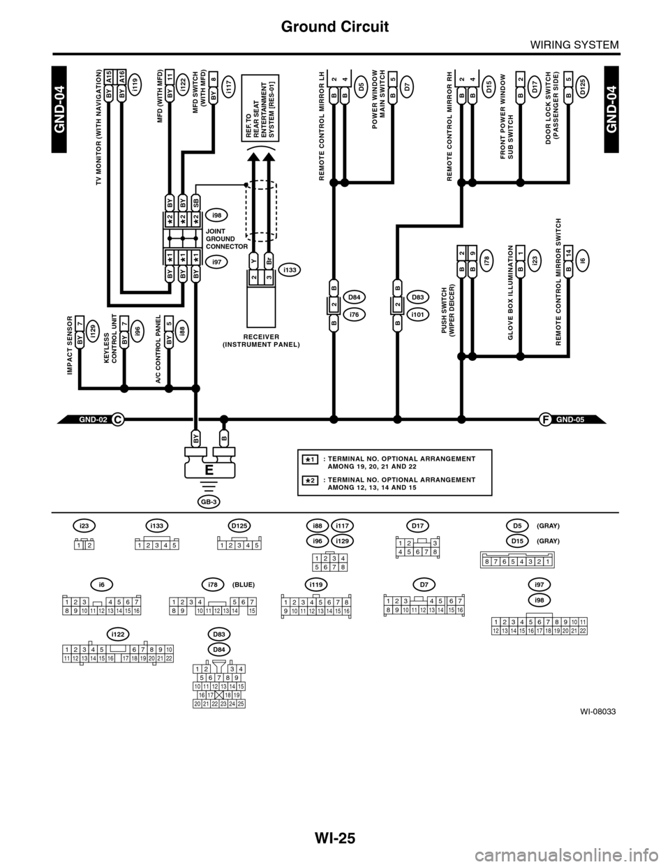
WI-25
Ground Circuit
WIRING SYSTEM
WI-08033
GND-04GND-04
i117BYi122BY 11
8
A/C CONTROL PANEL
i88BY 5
23
GND-05F
KEYLESS CONTROL UNIT
i96BY 7
IMPACT SENSOR
i129BY 7
TV MONITOR (WITH NAVIGATION)
i119BY A15BY A16
GND-02C
GB-3
BBY
D83
MFD (WITH MFD)MFD SWITCH (WITH MFD)
i96
12345678
i6
42
14
REMOTE CONTROL MIRROR SWITCH
i97i133
i98
JOINTGROUNDCONNECTOR
RECEIVER(INSTRUMENT PANEL)
2*2*
1*1*
2*
1*
BYBi231
GLOVE BOX ILLUMINATION
Bi789
PUSH SWITCH(WIPER DEICER)
B
2
BBYBY
SBBYBY
YBr
REF. TOREAR SEATENTERTAINMENT SYSTEM [RES-01]
: TERMINAL NO. OPTIONAL ARRANGEMENT AMONG 19, 20, 21 AND 22
: TERMINAL NO. OPTIONAL ARRANGEMENT AMONG 12, 13, 14 AND 15
1*
2*
D125
5
DOOR LOCK SWITCH(PASSENGER SIDE)
BD17
2
FRONT POWER WINDOW SUB SWITCH
POWER WINDOW
MAIN SWITCH
BD75
BD15
REMOTE CONTROL MIRROR RH
BB
42D5
REMOTE CONTROL MIRROR LH
BB
i1012D83
B
B
i762D84
B
B
D84
i88
i129
i117
567821943
10
2422 23 25
1112131415161718192021
i98
i97
12345678910111213141516171819202122
D7
12345689101112131514716
D17
12345678
D5
D15
87654321
(GRAY)
(GRAY)
i6
12345678910111213141516
i119
123 8910412 13 14 15 1656711
i133
12345
12345678910111213141516171819202122
i122
i78
123456789101112131415
(BLUE)
i23
12
D125
12345
Page 2311 of 2453
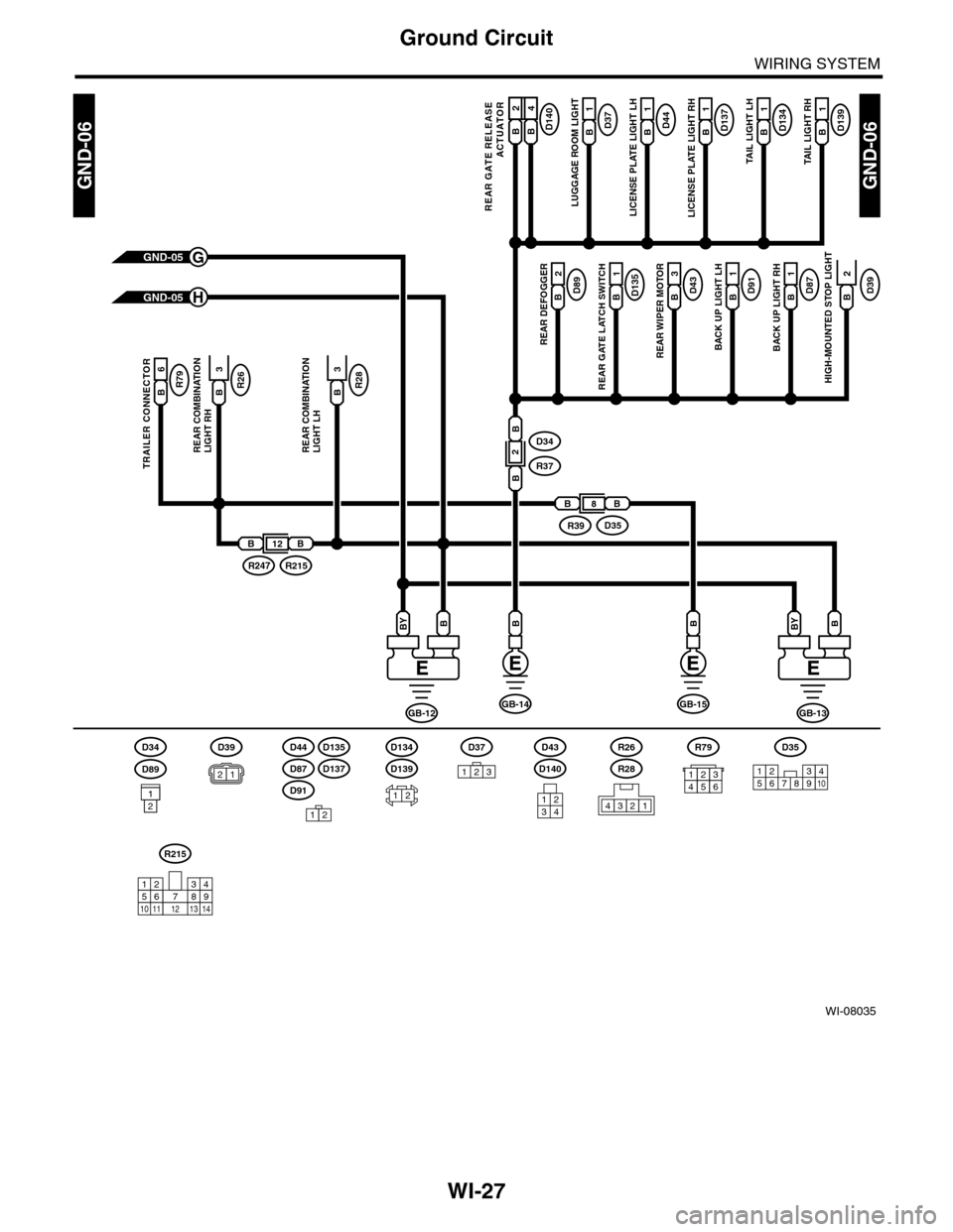
WI-27
Ground Circuit
WIRING SYSTEM
WI-08035
GND-06GND-06
D140B A16
REAR GATE RELEASE
ACTUATOR
GND-05G
GND-05H
BB
GB-12
BBY
GB-13
BBY
GB-15GB-14
D35
12345678910
D139B2
1
B2B4
TAIL LIGHT RH
D134B2
1
TAIL LIGHT LH
D137B2
1
LICENSE PLATE LIGHT RH
D44B2
1
LICENSE PLATE LIGHT LH
D37B2
1
LUGGAGE ROOM LIGHT
D39B
HIGH-MOUNTED STOP LIGHT
D87B2
1
BACK UP LIGHT RH
D91B2
1
BACK UP LIGHT LH
D43B2
3
REAR WIPER MOTOR
D135B2
1
REAR GATE LATCH SWITCH
D89B2
2
REAR DEFOGGER
R79B
TRAILER CONNECTOR
D34
R37
B
2
B
26
R26B3
REAR COMBINATION LIGHT RH
R28B3
REAR COMBINATIONLIGHT LH
2
BB8
D35R39
BB12
R215R247
D39
12D139
D134D44
D91
D135
D87D137D140
D43
121234
D34
D89
121
R215
12
10115634897131412
12
D37
123
R26
R28
4321
R79
123456