Page 699 of 2453
WW-4
General Description
WIPER AND WASHER SYSTEMS
3. WASHER TANK
C: CAUTION
•Connect the connectors and hoses securely during reassembly.
•After reassembly, make sure functional parts operate smoothly.
•Be careful with the airbag system wire harness which passes near electrical parts and switches.
•All airbag system wiring harness and connectors are colored yellow. Do not use a tester equipment on
these circuits.
•Care must be taken when connecting the hoses to pipes so that there are no bends or blockage.
•If even a small amount of silicon oil or grease enters tank and washer fluid passages, an oil film will be
formed on the glass and will cause the wiper to chatter and judder. Make sure that no oil comes into contact
with the system.
(1) Washer nozzle (5) Front washer motorTightening torque: N·m (kgf-m, ft-lb)
(2) Washer hose (6) Rear washer motorT: 6.0 (0.61, 4.4)
(3) Washer tank (7) Grommet
(4) Washer tank cap (8) Washer motor cover
Page 700 of 2453
WW-5
Wiper and Washer System
WIPER AND WASHER SYSTEMS
2. Wiper and Washer System
A: WIRING DIAGRAM
1. WIPER AND WASHER (FRONT)
2. WIPER AND WASHER (REAR)
B: INSPECTION
Symptom Repair order
Wiper and washers do not operate. 1. Wiper fuse (Front: F/B No. 30, Rear : F/B No. 23)
2. Combination switch
3. Wiper motor assembly
4. Wiring harness
5. Wiper relay unit
6. Body integrated unit (rear wiper only)
Wipers do not operate in LO or HI. 1. Combination switch
2. Wiper motor assembly
3. Wiring harness
4. Wiper relay unit
Wipers do not operate in INT. 1. Combination switch
2. Wiper motor assembly
3. Wiring harness
4. Body integrated unit (rear wiper only)
Wa sh e r mo to r do e s n ot o pe ra t e. 1 . Wa sh e r swit c h
2. Washer motor
3. Wiring harness
Wipers do not operate when washer switch is ON. 1. Wiper motor assembly
2. Wiring harness
Wa sh e r fl u id sp ray do e s n ot op e ra te pr o p er l y. 1 . Wa sh e r m ot o r
2. Washer hose and nozzle
Page 701 of 2453

WW-6
Combination Switch (Wiper)
WIPER AND WASHER SYSTEMS
3. Combination Switch (Wiper)
A: REMOVAL
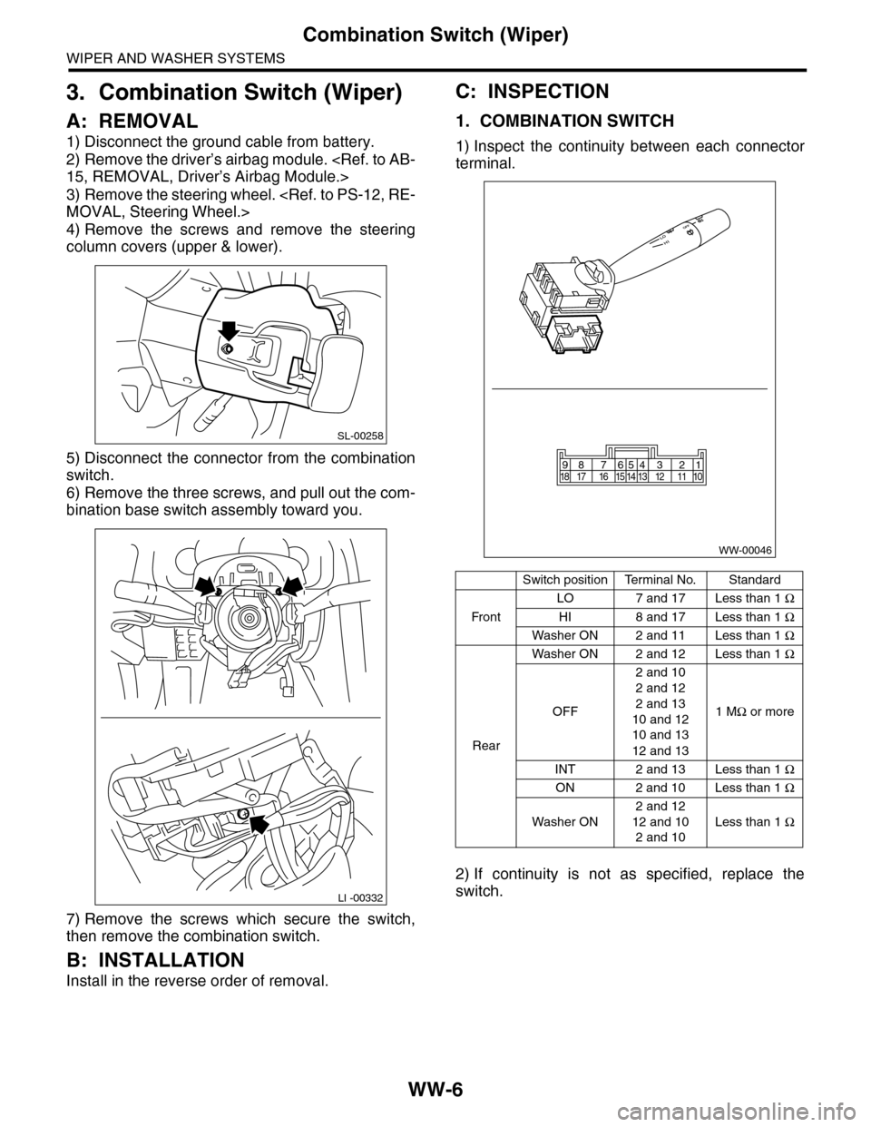
1) Disconnect the ground cable from battery.
2) Remove the driver’s airbag module.
15, REMOVAL, Driver’s Airbag Module.>
3) Remove the steering wheel.
MOVAL, Steering Wheel.>
4) Remove the screws and remove the steering
column covers (upper & lower).
5) Disconnect the connector from the combination
switch.
6) Remove the three screws, and pull out the com-
bination base switch assembly toward you.
7) Remove the screws which secure the switch,
then remove the combination switch.
B: INSTALLATION
Install in the reverse order of removal.
C: INSPECTION
1. COMBINATION SWITCH
1) Inspect the continuity between each connector
terminal.
2) If continuity is not as specified, replace the
switch.
SL-00258
LI -00332
Switch positionTerminal No.Standard
Fr o n t
LO 7 and 17 Less than 1 Ω
HI 8 and 17 Less than 1 Ω
Washer ON 2 and 11 Less than 1 Ω
Rear
Washer ON 2 and 12 Less than 1 Ω
OFF
2 and 10
2 and 12
2 and 13
10 and 12
10 and 13
12 and 13
1 MΩ or more
INT 2 and 13 Less than 1 Ω
ON 2 and 10 Less than 1 Ω
Washer ON
2 and 12
12 and 10
2 and 10
Less than 1 Ω
WW-00046
87654321917 16 15 14 13 12 11 1018
Page 703 of 2453

WW-8
Combination Switch (Wiper)
WIPER AND WASHER SYSTEMS
(3) CHECK THE VEHICLE SPEED SIGNAL
HARNESS.
Measure the resistance between the wiper
switch connector and the VDC control module.
Terminals
Wiper switch connector No. 15 — VDC con-
trol module No. 33:
3. REAR WIPER
1) Check with Subaru Select Monitor
Check Yes No
Is the resistance 0 Ω?Replace the
wiper switch.
Repair the har-
ness.
Step Check Yes No
1 CHECK INPUT OF REAR WIPER SWITCH.
Check the input from body integrated unit
using the Subaru Select Monitor.
1) Connect the Subaru Select Monitor to data
link connector.
2) Turn the ignition switch to ON.
3) Select {Integ. unit} from main menu.
4) Select the {Current Data Display & Save}.
5) Check the input of the rear wiper switch.
Is the input normal? Go to step 2.Check the rear
wiper switch.
to WW-6,
INSPECTION,
Combination
Switch (Wiper).>
2CHECK OUTPUT OF BODY INTEGRATED
UNIT.
When the rear wiper switch is operated, check
the output using the Subaru Select Monitor.
1) Turn the ignition switch to ON.
2) Operate the rear wiper switch and set to
each position of ON and INT.
3) At this time, check the body integrated unit
output.
When set to ON, is ON output
continuous? When set to INT,
is ON/OFF output repeated?
(INT OFF time (when vehicle
parked): 12 seconds)
Check the rear
wiper motor.
to WW-19,
INSPECTION,
Rear Wiper
Motor.>
Replace the body
integrated unit.
Body Integrated
Unit.>
Page 704 of 2453

WW-9
Combination Switch (Wiper)
WIPER AND WASHER SYSTEMS
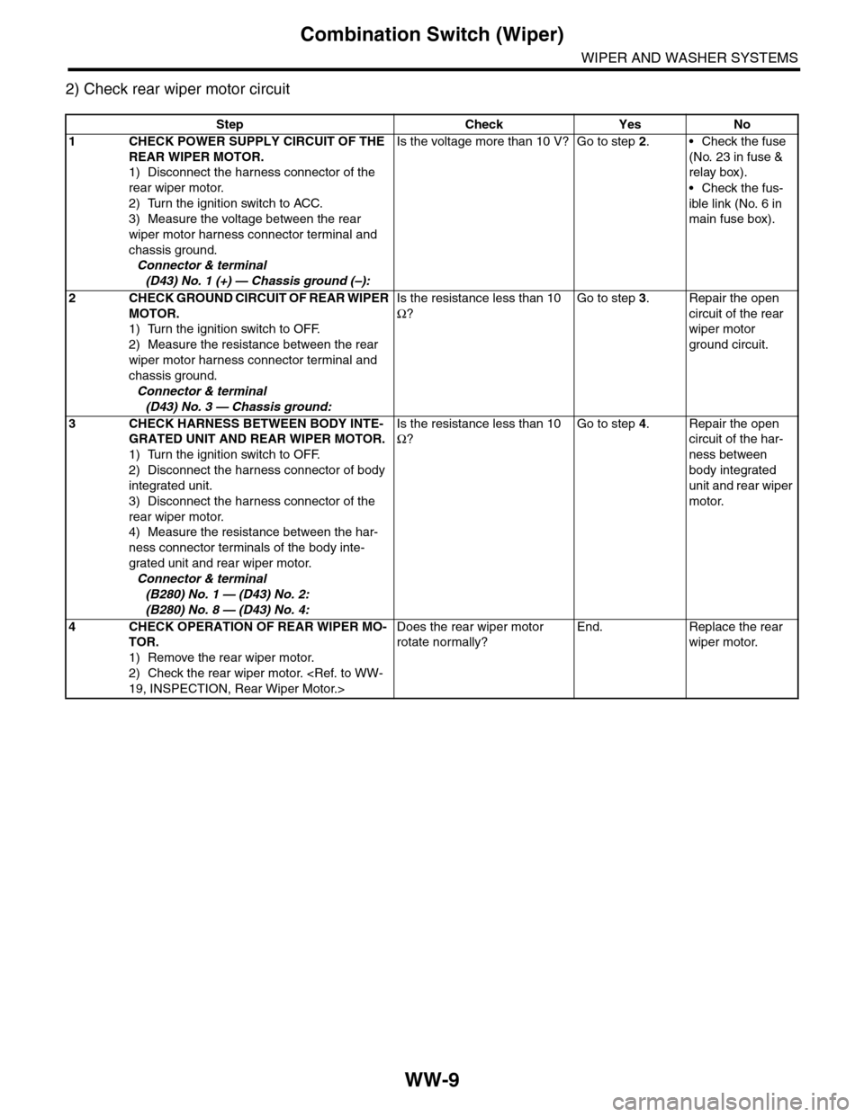
2) Check rear wiper motor circuit
Step Check Yes No
1CHECK POWER SUPPLY CIRCUIT OF THE
REAR WIPER MOTOR.
1) Disconnect the harness connector of the
rear wiper motor.
2) Turn the ignition switch to ACC.
3) Measure the voltage between the rear
wiper motor harness connector terminal and
chassis ground.
Connector & terminal
(D43) No. 1 (+) — Chassis ground (–):
Is the voltage more than 10 V? Go to step 2.•Check the fuse
(No. 23 in fuse &
relay box).
•Check the fus-
ible link (No. 6 in
main fuse box).
2CHECK GROUND CIRCUIT OF REAR WIPER
MOTOR.
1) Turn the ignition switch to OFF.
2) Measure the resistance between the rear
wiper motor harness connector terminal and
chassis ground.
Connector & terminal
(D43) No. 3 — Chassis ground:
Is the resistance less than 10
Ω?
Go to step 3.Repair the open
circuit of the rear
wiper motor
ground circuit.
3CHECK HARNESS BETWEEN BODY INTE-
GRATED UNIT AND REAR WIPER MOTOR.
1) Turn the ignition switch to OFF.
2) Disconnect the harness connector of body
integrated unit.
3) Disconnect the harness connector of the
rear wiper motor.
4) Measure the resistance between the har-
ness connector terminals of the body inte-
grated unit and rear wiper motor.
Connector & terminal
(B280) No. 1 — (D43) No. 2:
(B280) No. 8 — (D43) No. 4:
Is the resistance less than 10
Ω?
Go to step 4.Repair the open
circuit of the har-
ness between
body integrated
unit and rear wiper
motor.
4CHECK OPERATION OF REAR WIPER MO-
TOR.
1) Remove the rear wiper motor.
2) Check the rear wiper motor.
19, INSPECTION, Rear Wiper Motor.>
Does the rear wiper motor
rotate normally?
End. Replace the rear
wiper motor.
Page 705 of 2453

WW-10
Wiper Blade
WIPER AND WASHER SYSTEMS
4. Wiper Blade
A: REMOVAL
CAUTION:
When replacing the wiper blade, if standing up
the wiper arm, be sure to stand up the driver’s
side wiper arm first, and then passenger’s side
wiper arm next. Also, when putting the wiper
arms back, be sure to start with passenger’s
side first, then driver’s side next. Doing this in
the reverse order may result in the driver’s side
wiper blade hitting the passenger’s side wiper
arm and causing damage.
1. FRONT
While pushing the locking clip to the direction of the
arrow, pull out and remove the blade from the arm.
2. REAR
Turn the blade in the direction of arrow (A) and re-
move it from arm.
B: INSTALLATION
1) Install in the reverse order of removal.
2) Confirm that the clip is locked securely.
C: DISASSEMBLY
1. FRONT
Pull side (A) of the wiper rubber stopper and re-
move the rubber from the blade assembly.
2. REAR
Pull the wiper rubber top slightly from stopper (A)
and pull out completely.
WW-00354
(A) Turn the wiper blade.
(1) Wiper arm
(2) Wiper blade
(3) Wiper blade attachment section
(1)
(2)
(3)(A)WW-00207
WW-00009
WW-00143
(A)
Page 706 of 2453
WW-11
Wiper Blade
WIPER AND WASHER SYSTEMS
D: ASSEMBLY
1. FRONT
1) Insert the wiper rubber onto the blade so that the
stopper is in the position shown in the figure.
2) Make sure the wiper rubber is securely fastened
to pull stopper (A).
2. REAR
WW-00230
WW-00037
WW-00193
ABCD
Page 713 of 2453
WW-18
Rear Wiper Arm
WIPER AND WASHER SYSTEMS
10.Rear Wiper Arm
A: REMOVAL
1) Detach the wiper arm cover (A).
2) Remove the nut (B) to remove the wiper arm.
B: INSTALLATION
1) Install in the reverse order of removal.
2) Operate the rear wiper once.
3) Align the blade with the marking (A) of the glass.
Tightening torque:
Refer to “COMPONENT” of “General Descrip-
tion”.
General Description.>
C: ADJUSTMENT
1) Operate the rear wiper once.
2) Align the blade with the marking (A) of the glass.
WW-00179
(A)
(B)
WW-00361
(A)
WW-00361
(A)