2009 SUBARU TRIBECA display
[x] Cancel search: displayPage 2048 of 2453
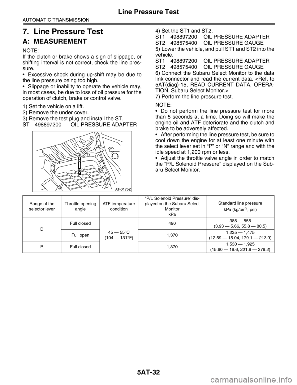
5AT-32
Line Pressure Test
AUTOMATIC TRANSMISSION
7. Line Pressure Test
A: MEASUREMENT
NOTE:
If the clutch or brake shows a sign of slippage, or
shifting interval is not correct, check the line pres-
sure.
•Excessive shock during up-shift may be due to
the line pressure being too high.
•Slippage or inability to operate the vehicle may,
in most cases, be due to loss of oil pressure for the
operation of clutch, brake or control valve.
1) Set the vehicle on a lift.
2) Remove the under cover.
3) Remove the test plug and install the ST.
ST 498897200 OIL PRESSURE ADAPTER
4) Set the ST1 and ST2.
ST1 498897200 OIL PRESSURE ADAPTER
ST2 498575400 OIL PRESSURE GAUGE
5) Lower the vehicle, and pull ST1 and ST2 into the
vehicle.
ST1 498897200 OIL PRESSURE ADAPTER
ST2 498575400 OIL PRESSURE GAUGE
6) Connect the Subaru Select Monitor to the data
link connector and read the current data.
TION, Subaru Select Monitor.>
7) Perform the line pressure test.
NOTE:
•Do not perform the line pressure test for more
than 5 seconds at a time. Doing so will make the
engine oil and ATF deteriorate and the clutch and
brake to be adversely affected.
•After performing the line pressure test, be sure to
cool down the engine for at least one minute with
the select lever set in “P” or “N” range and with the
idle speed at 1,200 rpm or less.
•Adjust the throttle valve angle in order to match
the “P/L Solenoid Pressure” displayed on the Sub-
aru Select Monitor.
AT-01752
Range of the
selector lever
Throttle opening
angle
AT F t e m p e r a t u r e
condition
“P/L Solenoid Pressure” dis-
played on the Subaru Select
Monitor
kPa
Standard line pressure
kPa (kg/cm2, psi)
D
Full closed
45 — 55°C
(104 — 131°F)
490385 — 555
(3.93 — 5.66, 55.8 — 80.5)
Full open 1,3701,235 — 1,475
(12.59 — 15.04, 179.1 — 213.9)
RFull closed 1,3701,530 — 1,925
(15.60 — 19.6, 221.9 — 279.2)
Page 2049 of 2453
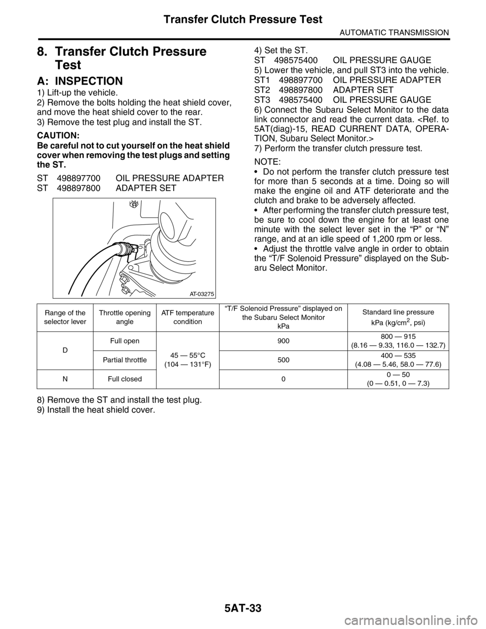
5AT-33
Transfer Clutch Pressure Test
AUTOMATIC TRANSMISSION
8. Transfer Clutch Pressure
Test
A: INSPECTION
1) Lift-up the vehicle.
2) Remove the bolts holding the heat shield cover,
and move the heat shield cover to the rear.
3) Remove the test plug and install the ST.
CAUTION:
Be careful not to cut yourself on the heat shield
cover when removing the test plugs and setting
the ST.
ST 498897700 OIL PRESSURE ADAPTER
ST 498897800 ADAPTER SET
4) Set the ST.
ST 498575400 OIL PRESSURE GAUGE
5) Lower the vehicle, and pull ST3 into the vehicle.
ST1 498897700 OIL PRESSURE ADAPTER
ST2 498897800 ADAPTER SET
ST3 498575400 OIL PRESSURE GAUGE
6) Connect the Subaru Select Monitor to the data
link connector and read the current data.
TION, Subaru Select Monitor.>
7) Perform the transfer clutch pressure test.
NOTE:
•Do not perform the transfer clutch pressure test
for more than 5 seconds at a time. Doing so will
make the engine oil and ATF deteriorate and the
clutch and brake to be adversely affected.
•After performing the transfer clutch pressure test,
be sure to cool down the engine for at least one
minute with the select lever set in the “P” or “N”
range, and at an idle speed of 1,200 rpm or less.
•Adjust the throttle valve angle in order to obtain
the “T/F Solenoid Pressure” displayed on the Sub-
aru Select Monitor.
8) Remove the ST and install the test plug.
9) Install the heat shield cover.
AT-03275
Range of the
selector lever
Throttle opening
angle
AT F t e m p e r a t u r e
condition
“T/F Solenoid Pressure” displayed on
the Subaru Select Monitor
kPa
Standard line pressure
kPa (kg/cm2, psi)
D
Full open
45 — 55°C
(104 — 131°F)
900800 — 915
(8.16 — 9.33, 116.0 — 132.7)
Par tial throttle 500400 — 535
(4.08 — 5.46, 58.0 — 77.6)
NFull closed 00 — 50
(0 — 0.51, 0 — 7.3)
Page 2119 of 2453
5AT(diag)-2
Basic Diagnostic Procedure
AUTOMATIC TRANSMISSION (DIAGNOSTICS)
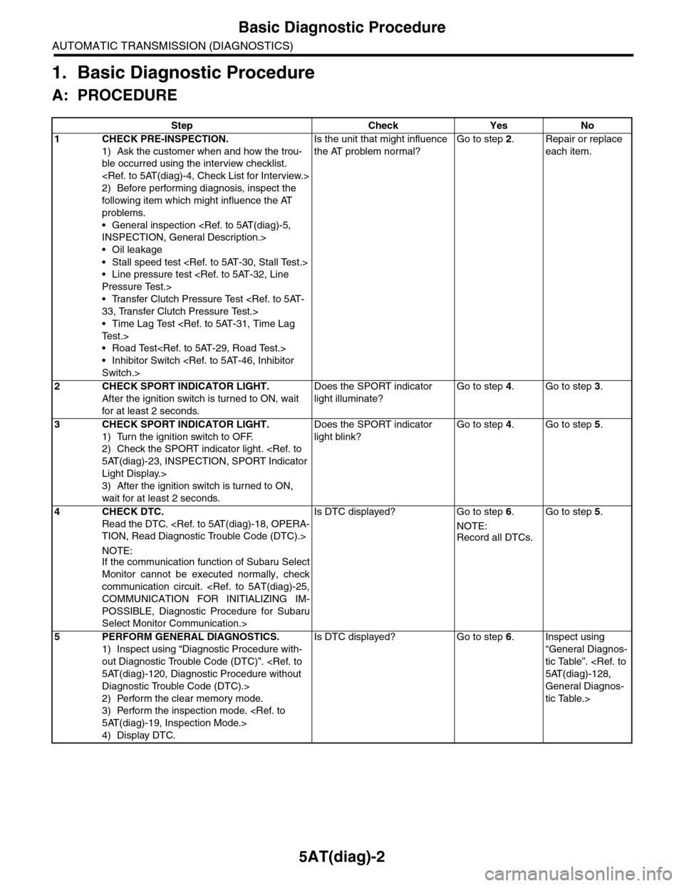
1. Basic Diagnostic Procedure
A: PROCEDURE
Step Check Yes No
1CHECK PRE-INSPECTION.
1) Ask the customer when and how the trou-
ble occurred using the interview checklist.
2) Before performing diagnosis, inspect the
following item which might influence the AT
problems.
•General inspection
•Oil leakage
•Stall speed test
•Line pressure test
•Transfer Clutch Pressure Test
•Time Lag Test
•Road Test
•Inhibitor Switch
Is the unit that might influence
the AT problem normal?
Go to step 2.Repair or replace
each item.
2CHECK SPORT INDICATOR LIGHT.
After the ignition switch is turned to ON, wait
for at least 2 seconds.
Does the SPORT indicator
light illuminate?
Go to step 4.Go to step 3.
3CHECK SPORT INDICATOR LIGHT.
1) Turn the ignition switch to OFF.
2) Check the SPORT indicator light.
Light Display.>
3) After the ignition switch is turned to ON,
wait for at least 2 seconds.
Does the SPORT indicator
light blink?
Go to step 4.Go to step 5.
4CHECK DTC.
Read the DTC.
NOTE:If the communication function of Subaru Select
Monitor cannot be executed normally, check
communication circuit.
POSSIBLE, Diagnostic Procedure for Subaru
Select Monitor Communication.>
Is DTC displayed? Go to step 6.
NOTE:
Record all DTCs.
Go to step 5.
5PERFORM GENERAL DIAGNOSTICS.
1) Inspect using “Diagnostic Procedure with-
out Diagnostic Trouble Code (DTC)”.
Diagnostic Trouble Code (DTC).>
2) Perform the clear memory mode.
3) Perform the inspection mode.
4) Display DTC.
Is DTC displayed? Go to step 6.Inspect using
“General Diagnos-
tic Table”.
General Diagnos-
tic Table.>
Page 2120 of 2453
5AT(diag)-3
Basic Diagnostic Procedure
AUTOMATIC TRANSMISSION (DIAGNOSTICS)
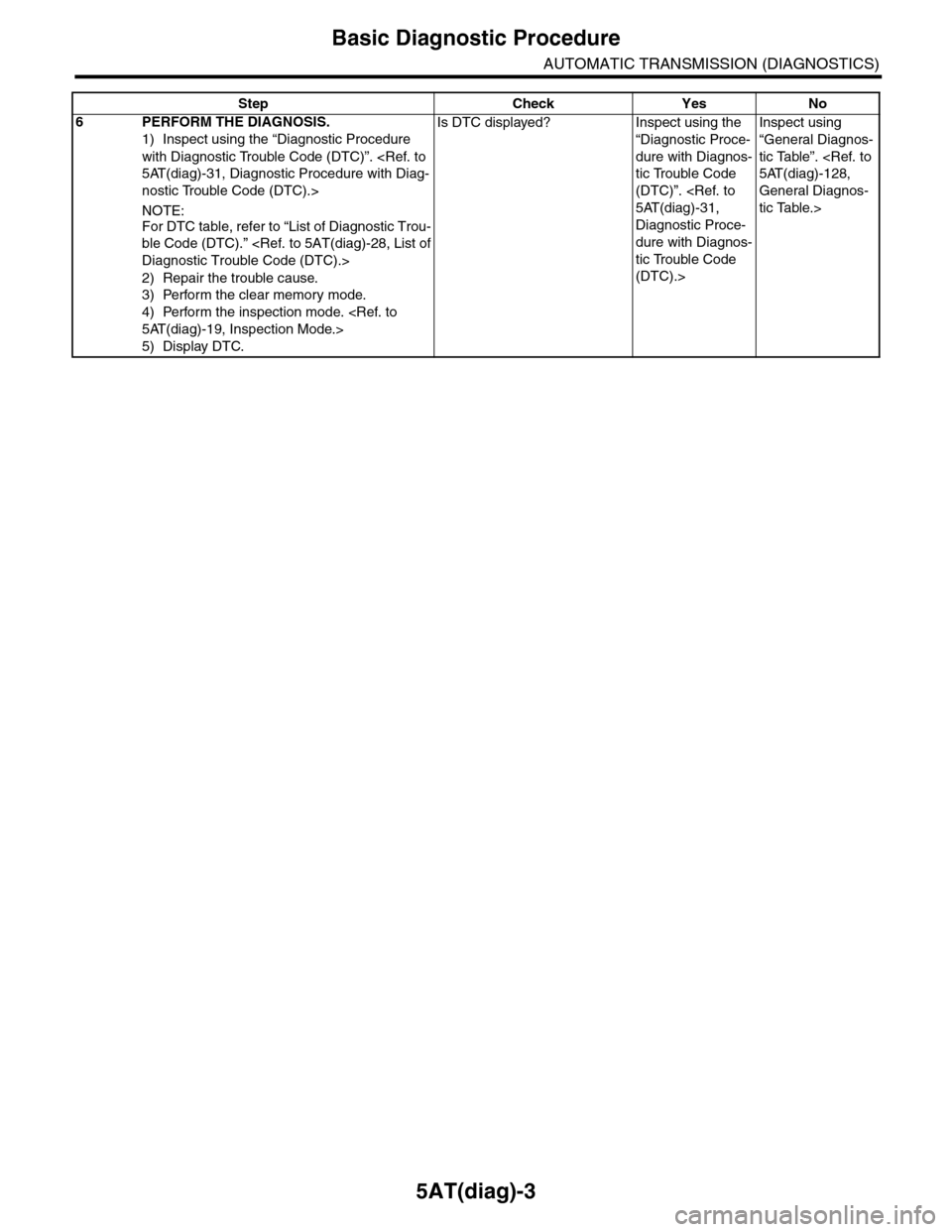
6PERFORM THE DIAGNOSIS.
1) Inspect using the “Diagnostic Procedure
with Diagnostic Trouble Code (DTC)”.
nostic Trouble Code (DTC).>
NOTE:
For DTC table, refer to “List of Diagnostic Trou-
ble Code (DTC).”
2) Repair the trouble cause.
3) Perform the clear memory mode.
4) Perform the inspection mode.
5) Display DTC.
Is DTC displayed? Inspect using the
“Diagnostic Proce-
dure with Diagnos-
tic Trouble Code
(DTC)”.
Diagnostic Proce-
dure with Diagnos-
tic Trouble Code
(DTC).>
Inspect using
“General Diagnos-
tic Table”.
General Diagnos-
tic Table.>
Step Check Yes No
Page 2132 of 2453
5AT(diag)-15
Subaru Select Monitor
AUTOMATIC TRANSMISSION (DIAGNOSTICS)
6. Subaru Select Monitor
A: OPERATION
1. READ DIAGNOSTIC TROUBLE CODE
(DTC)
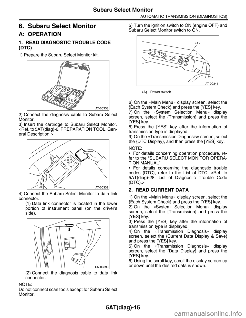
1) Prepare the Subaru Select Monitor kit.
2) Connect the diagnosis cable to Subaru Select
Monitor.
3) Insert the cartridge to Subaru Select Monitor.
4) Connect the Subaru Select Monitor to data link
connector.
(1) Data link connector is located in the lower
portion of instrument panel (on the driver's
side).
(2) Connect the diagnosis cable to data link
connector.
NOTE:
Do not connect scan tools except for Subaru Select
Monitor.
5) Turn the ignition switch to ON (engine OFF) and
Subaru Select Monitor switch to ON.
6) On the «Main Menu» display screen, select the
{Each System Check} and press the [YES] key.
7) On the «System Selection Menu» display
screen, select the {Transmission} and press the
[YES] key.
8) Press the [YES] key after the information of
transmission type is displayed.
9) On the «Transmission Diagnosis» screen, select
the {DTC Display}, and then press the [YES] key.
NOTE:
•For details concerning operation procedure, re-
fer to the “SUBARU SELECT MONITOR OPERA-
TION MANUAL”.
•For details concerning the diagnostic trouble
codes (DTC), refer to the List of DTC.
(DTC).>
2. READ CURRENT DATA
1) On the «Main Menu» display screen, select the
{Each System Check} and press the [YES] key.
2) On the «System Selection Menu» display
screen, select the {Transmission} and press the
[YES] key.
3) Press the [YES] key after the information of
transmission type is displayed.
4) On the «Transmission Diagnosis» display
screen, select the {Current Data Display & Save}
and press the [YES] key.
5) On the «Transmission Diagnosis» display
screen, select the {Data Display} and press the
[YES] key.
6) Using the scroll key, scroll the display screen up
or down until the desired data is shown.
AT-00338
AT-00339
EN-03693
(A) Power switch
(A)
AT-00341
Page 2133 of 2453
5AT(diag)-16
Subaru Select Monitor
AUTOMATIC TRANSMISSION (DIAGNOSTICS)
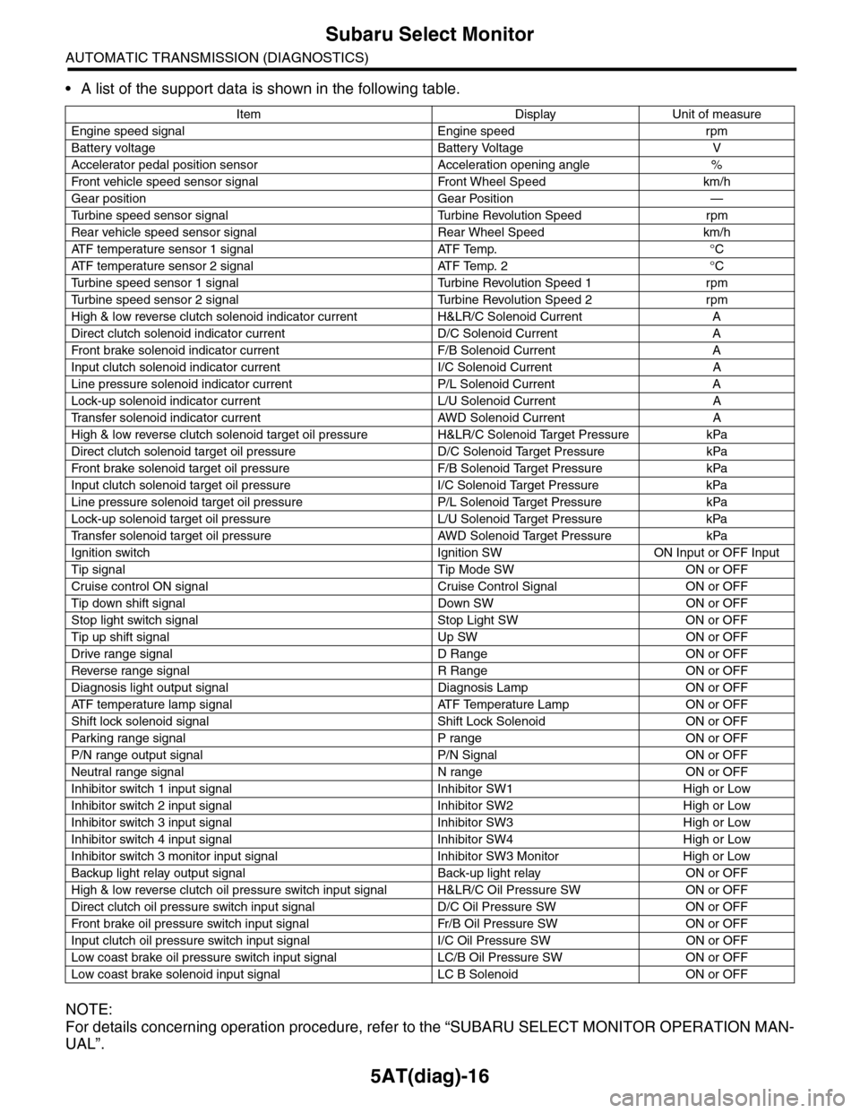
•A list of the support data is shown in the following table.
NOTE:
For details concerning operation procedure, refer to the “SUBARU SELECT MONITOR OPERATION MAN-
UAL”.
Item Display Unit of measure
Engine speed signal Engine speed rpm
Battery voltage Battery Voltage V
Accelerator pedal position sensor Acceleration opening angle %
Fr o nt veh ic l e sp e ed se n so r s ig n al Fr o n t W h ee l S p e ed km/ h
Gear position Gear Position —
Tu r b i n e s p e e d s e n s o r s i g n a l Tu r b i n e R e v o l u t i o n S p e e d r p m
Rear vehicle speed sensor signal Rear Wheel Speed km/h
ATF temperature sensor 1 signal ATF Temp. °C
ATF temperature sensor 2 signal ATF Temp. 2 °C
Tu r b i n e s p e e d s e n s o r 1 s i g n a l Tu r b i n e R e v o l u t i o n S p e e d 1 r p m
Tu r b i n e s p e e d s e n s o r 2 s i g n a l Tu r b i n e R e v o l u t i o n S p e e d 2 r p m
High & low reverse clutch solenoid indicator current H&LR/C Solenoid Current A
Direct clutch solenoid indicator current D/C Solenoid Current A
Fr o nt b rake so l en oi d in di c at o r c u rr e n t F / B S o l en o id Cur r e nt A
Input clutch solenoid indicator current I/C Solenoid Current A
Line pressure solenoid indicator current P/L Solenoid Current A
Lock-up solenoid indicator current L/U Solenoid Current A
Tr a n s f e r s o l e n o i d i n d i c a t o r c u r r e n t A W D S o l e n o i d C u r r e n t A
High & low reverse clutch solenoid target oil pressure H&LR/C Solenoid Target Pressure kPa
Direct clutch solenoid target oil pressure D/C Solenoid Target Pressure kPa
Fr o nt b rake so l en oi d ta r g et o il pr e ss ur e F / B S o l en o id Ta r g et P r es su r e kPa
Input clutch solenoid target oil pressure I/C Solenoid Target Pressure kPa
Line pressure solenoid target oil pressure P/L Solenoid Target Pressure kPa
Lock-up solenoid target oil pressure L/U Solenoid Target Pressure kPa
Tr a n s f e r s o l e n o i d t a r g e t o i l p r e s s u r e A W D S o l e n o i d Ta r g e t P r e s s u r e k P a
Ignition switch Ignition SW ON Input or OFF Input
Tip signal Tip Mode SW ON or OFF
Cruise control ON signal Cruise Control Signal ON or OFF
Tip down shift signal Down SW ON or OFF
Stop light switch signal Stop Light SW ON or OFF
Tip up shift signal Up SW ON or OFF
Drive range signal D Range ON or OFF
Reverse range signal R Range ON or OFF
Diagnosis light output signal Diagnosis Lamp ON or OFF
AT F t e m p e r a t u r e l a m p s i g n a l AT F Te m p e r a t u r e L a m p O N o r O F F
Shift lock solenoid signal Shift Lock Solenoid ON or OFF
Par king range signal P range ON or OFF
P/N range output signal P/N Signal ON or OFF
Neutral range signal N range ON or OFF
Inhibitor switch 1 input signal Inhibitor SW1 High or Low
Inhibitor switch 2 input signal Inhibitor SW2 High or Low
Inhibitor switch 3 input signal Inhibitor SW3 High or Low
Inhibitor switch 4 input signal Inhibitor SW4 High or Low
Inhibitor switch 3 monitor input signal Inhibitor SW3 Monitor High or Low
Backup light relay output signal Back-up light relay ON or OFF
High & low reverse clutch oil pressure switch input signal H&LR/C Oil Pressure SW ON or OFF
Direct clutch oil pressure switch input signal D/C Oil Pressure SW ON or OFF
Fr o nt b rake oi l pr e ss ur e swi tc h i n pu t si gn a l Fr / B Oi l P r e ss ur e S W ON or OF F
Input clutch oil pressure switch input signal I/C Oil Pressure SW ON or OFF
Low coast brake oil pressure switch input signal LC/B Oil Pressure SW ON or OFF
Low coast brake solenoid input signal LC B Solenoid ON or OFF
Page 2134 of 2453
5AT(diag)-17
Subaru Select Monitor
AUTOMATIC TRANSMISSION (DIAGNOSTICS)
3. CLEAR MEMORY MODE
NOTE:
To clear the previous DTC, use {Clear Memory},
and to clear the learned value, use {Clear Memory
2}.
1) Check that the select lever is in “P” range.
2) On the «Main Menu» display screen, select the
{Each System Check} and press the [YES] key.
3) On the «System Selection Menu» display
screen, select the {Transmission} and press the
[YES] key.
4) Press the [YES] key after the information of
transmission type is displayed.
5) On the «Transmission Diagnosis» display
screen, select the {Clear Memory} and press the
[YES] key.
NOTE:
If {Clear Memory 2} is selected and performed,
DTC are not cleared.
6) When ‘Done’ is shown on the display screen,
turn off the Subaru Select Monitor and turn the ig-
nition switch to OFF. To turn the ignition switch to
ON again, wait for more than 10 seconds.
NOTE:
For details concerning operation procedure, refer
to the “SUBARU SELECT MONITOR OPERATION
MANUAL”.
Page 2139 of 2453
5AT(diag)-22
SPORT Indicator Light Display
AUTOMATIC TRANSMISSION (DIAGNOSTICS)
11.SPORT Indicator Light Display
A: OPERATION
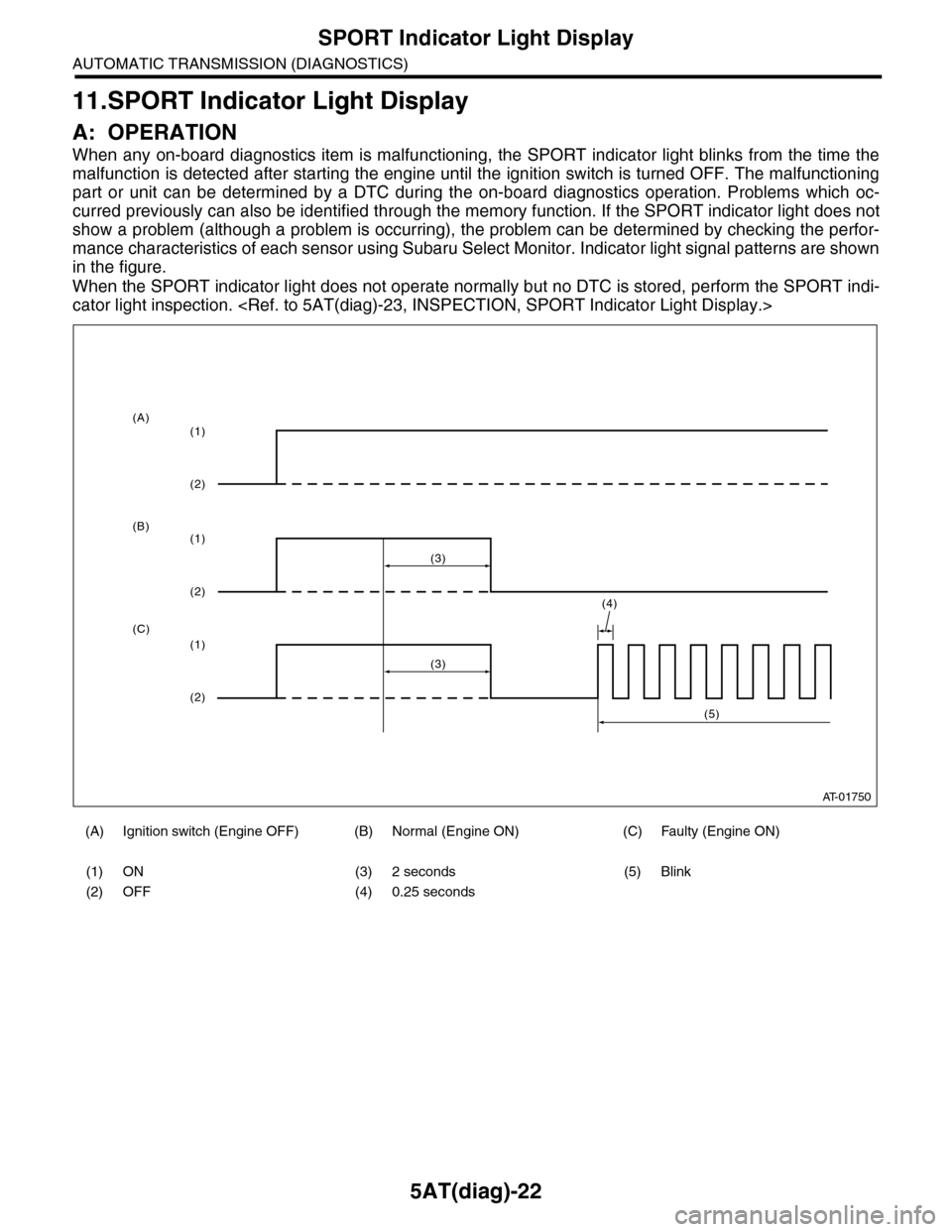
When any on-board diagnostics item is malfunctioning, the SPORT indicator light blinks from the time the
malfunction is detected after starting the engine until the ignition switch is turned OFF. The malfunctioning
part or unit can be determined by a DTC during the on-board diagnostics operation. Problems which oc-
curred previously can also be identified through the memory function. If the SPORT indicator light does not
show a problem (although a problem is occurring), the problem can be determined by checking the perfor-
mance characteristics of each sensor using Subaru Select Monitor. Indicator light signal patterns are shown
in the figure.
When the SPORT indicator light does not operate normally but no DTC is stored, perform the SPORT indi-
cator light inspection.
(A) Ignition switch (Engine OFF) (B) Normal (Engine ON) (C) Faulty (Engine ON)
(1) ON (3) 2 seconds (5) Blink
(2) OFF (4) 0.25 seconds
AT-01750
(4)
(3)
(1)
(2)
(1)
(2)
(1)
(2)
(3)
(5)
(A)
(B)
(C)