2009 SUBARU TRIBECA display
[x] Cancel search: displayPage 1500 of 2453
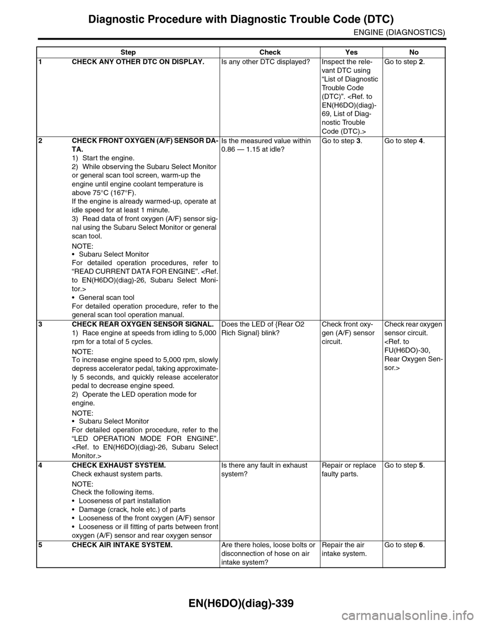
EN(H6DO)(diag)-339
Diagnostic Procedure with Diagnostic Trouble Code (DTC)
ENGINE (DIAGNOSTICS)
Step Check Yes No
1CHECK ANY OTHER DTC ON DISPLAY.Is any other DTC displayed? Inspect the rele-
vant DTC using
“List of Diagnostic
Tr o u b l e C o d e
(DTC)”.
69, List of Diag-
nostic Trouble
Code (DTC).>
Go to step 2.
2CHECK FRONT OXYGEN (A/F) SENSOR DA-
TA.
1) Start the engine.
2) While observing the Subaru Select Monitor
or general scan tool screen, warm-up the
engine until engine coolant temperature is
above 75°C (167°F).
If the engine is already warmed-up, operate at
idle speed for at least 1 minute.
3) Read data of front oxygen (A/F) sensor sig-
nal using the Subaru Select Monitor or general
scan tool.
NOTE:
•Subaru Select Monitor
For detailed operation procedures, refer to
“READ CURRENT DATA FOR ENGINE”.
tor.>
•General scan tool
For detailed operation procedure, refer to the
general scan tool operation manual.
Is the measured value within
0.86 — 1.15 at idle?
Go to step 3.Go to step 4.
3CHECK REAR OXYGEN SENSOR SIGNAL.
1) Race engine at speeds from idling to 5,000
rpm for a total of 5 cycles.
NOTE:To increase engine speed to 5,000 rpm, slowly
depress accelerator pedal, taking approximate-
ly 5 seconds, and quickly release accelerator
pedal to decrease engine speed.
2) Operate the LED operation mode for
engine.
NOTE:•Subaru Select Monitor
For detailed operation procedure, refer to the
“LED OPERATION MODE FOR ENGINE”.
Does the LED of {Rear O2
Rich Signal} blink?
Check front oxy-
gen (A/F) sensor
circuit.
Check rear oxygen
sensor circuit.
Rear Oxygen Sen-
sor.>
4 CHECK EXHAUST SYSTEM.
Check exhaust system parts.
NOTE:Check the following items.
•Looseness of part installation
•Damage (crack, hole etc.) of parts
•Looseness of the front oxygen (A/F) sensor
•Looseness or ill fitting of parts between front
oxygen (A/F) sensor and rear oxygen sensor
Is there any fault in exhaust
system?
Repair or replace
faulty par ts.
Go to step 5.
5CHECK AIR INTAKE SYSTEM.Are there holes, loose bolts or
disconnection of hose on air
intake system?
Repair the air
intake system.
Go to step 6.
Page 1508 of 2453
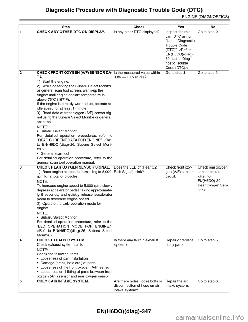
EN(H6DO)(diag)-347
Diagnostic Procedure with Diagnostic Trouble Code (DTC)
ENGINE (DIAGNOSTICS)
Step Check Yes No
1CHECK ANY OTHER DTC ON DISPLAY.Is any other DTC displayed? Inspect the rele-
vant DTC using
“List of Diagnostic
Tr o u b l e C o d e
(DTC)”.
69, List of Diag-
nostic Trouble
Code (DTC).>
Go to step 2.
2CHECK FRONT OXYGEN (A/F) SENSOR DA-
TA.
1) Start the engine.
2) While observing the Subaru Select Monitor
or general scan tool screen, warm-up the
engine until engine coolant temperature is
above 75°C (167°F).
If the engine is already warmed-up, operate at
idle speed for at least 1 minute.
3) Read data of front oxygen (A/F) sensor sig-
nal using the Subaru Select Monitor or general
scan tool.
NOTE:
•Subaru Select Monitor
For detailed operation procedures, refer to
“READ CURRENT DATA FOR ENGINE”.
tor.>
•General scan tool
For detailed operation procedure, refer to the
general scan tool operation manual.
Is the measured value within
0.86 — 1.15 at idle?
Go to step 3.Go to step 4.
3CHECK REAR OXYGEN SENSOR SIGNAL.
1) Race engine at speeds from idling to 5,000
rpm for a total of 5 cycles.
NOTE:To increase engine speed to 5,000 rpm, slowly
depress accelerator pedal, taking approximate-
ly 5 seconds, and quickly release accelerator
pedal to decrease engine speed.
2) Operate the LED operation mode for
engine.
NOTE:•Subaru Select Monitor
For detailed operation procedure, refer to the
“LED OPERATION MODE FOR ENGINE.”.
Does the LED of {Rear O2
Rich Signal} blink?
Check front oxy-
gen (A/F) sensor
circuit.
Check rear oxygen
sensor circuit.
Rear Oxygen Sen-
sor.>
4 CHECK EXHAUST SYSTEM.
Check exhaust system parts.
NOTE:Check the following items.
•Looseness of part installation
•Damage (crack, hole etc.) of parts
•Looseness of the front oxygen (A/F) sensor
•Looseness or ill fitting of parts between front
oxygen (A/F) sensor and rear oxygen sensor
Is there any fault in exhaust
system?
Repair or replace
faulty par ts.
Go to step 5.
5CHECK AIR INTAKE SYSTEM.Are there holes, loose bolts or
disconnection of hose on air
intake system?
Repair the air
intake system.
Go to step 6.
Page 1516 of 2453
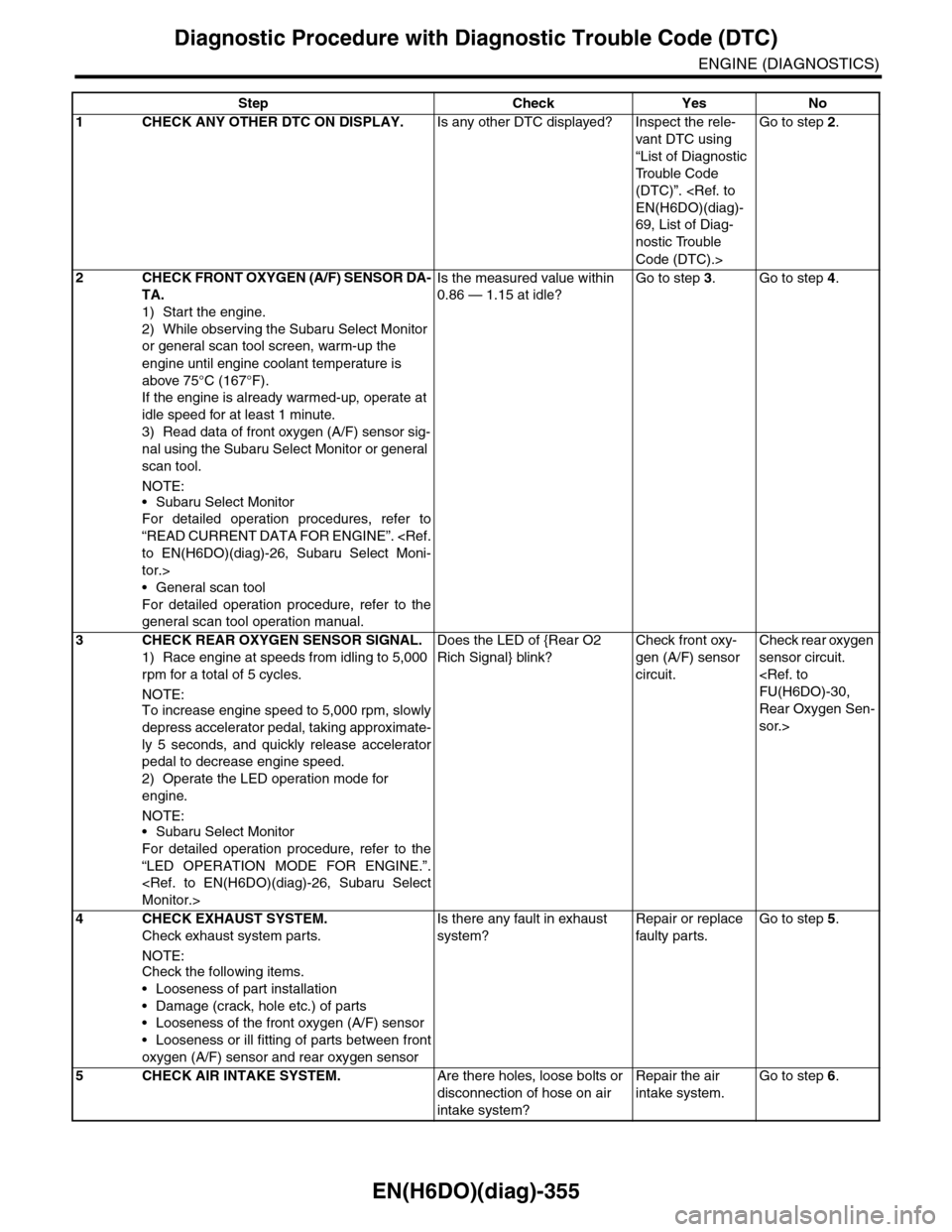
EN(H6DO)(diag)-355
Diagnostic Procedure with Diagnostic Trouble Code (DTC)
ENGINE (DIAGNOSTICS)
Step Check Yes No
1CHECK ANY OTHER DTC ON DISPLAY.Is any other DTC displayed? Inspect the rele-
vant DTC using
“List of Diagnostic
Tr o u b l e C o d e
(DTC)”.
69, List of Diag-
nostic Trouble
Code (DTC).>
Go to step 2.
2CHECK FRONT OXYGEN (A/F) SENSOR DA-
TA.
1) Start the engine.
2) While observing the Subaru Select Monitor
or general scan tool screen, warm-up the
engine until engine coolant temperature is
above 75°C (167°F).
If the engine is already warmed-up, operate at
idle speed for at least 1 minute.
3) Read data of front oxygen (A/F) sensor sig-
nal using the Subaru Select Monitor or general
scan tool.
NOTE:
•Subaru Select Monitor
For detailed operation procedures, refer to
“READ CURRENT DATA FOR ENGINE”.
tor.>
•General scan tool
For detailed operation procedure, refer to the
general scan tool operation manual.
Is the measured value within
0.86 — 1.15 at idle?
Go to step 3.Go to step 4.
3CHECK REAR OXYGEN SENSOR SIGNAL.
1) Race engine at speeds from idling to 5,000
rpm for a total of 5 cycles.
NOTE:To increase engine speed to 5,000 rpm, slowly
depress accelerator pedal, taking approximate-
ly 5 seconds, and quickly release accelerator
pedal to decrease engine speed.
2) Operate the LED operation mode for
engine.
NOTE:•Subaru Select Monitor
For detailed operation procedure, refer to the
“LED OPERATION MODE FOR ENGINE.”.
Does the LED of {Rear O2
Rich Signal} blink?
Check front oxy-
gen (A/F) sensor
circuit.
Check rear oxygen
sensor circuit.
Rear Oxygen Sen-
sor.>
4 CHECK EXHAUST SYSTEM.
Check exhaust system parts.
NOTE:Check the following items.
•Looseness of part installation
•Damage (crack, hole etc.) of parts
•Looseness of the front oxygen (A/F) sensor
•Looseness or ill fitting of parts between front
oxygen (A/F) sensor and rear oxygen sensor
Is there any fault in exhaust
system?
Repair or replace
faulty par ts.
Go to step 5.
5CHECK AIR INTAKE SYSTEM.Are there holes, loose bolts or
disconnection of hose on air
intake system?
Repair the air
intake system.
Go to step 6.
Page 1551 of 2453
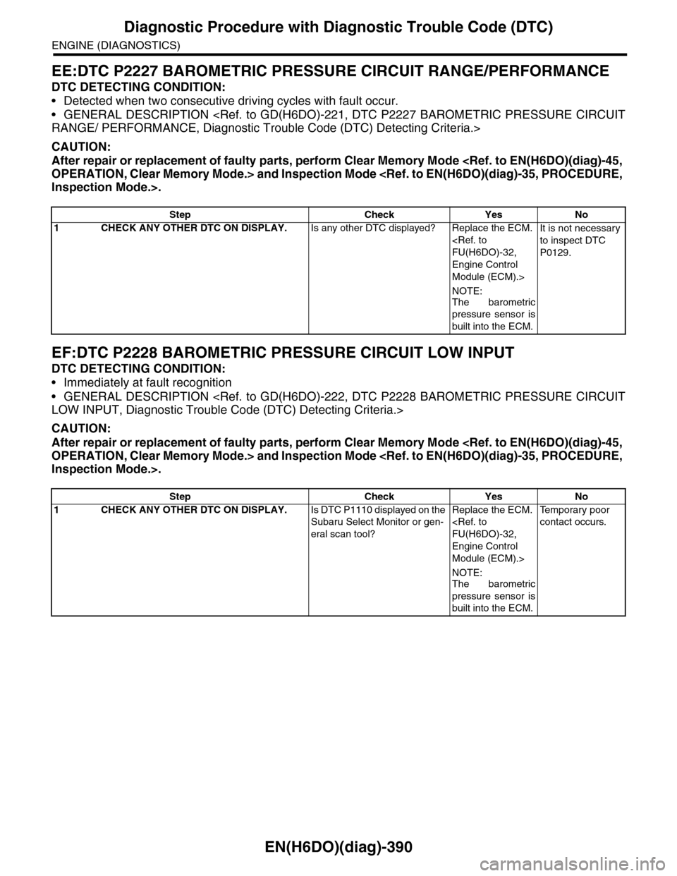
EN(H6DO)(diag)-390
Diagnostic Procedure with Diagnostic Trouble Code (DTC)
ENGINE (DIAGNOSTICS)
EE:DTC P2227 BAROMETRIC PRESSURE CIRCUIT RANGE/PERFORMANCE
DTC DETECTING CONDITION:
•Detected when two consecutive driving cycles with fault occur.
•GENERAL DESCRIPTION
CAUTION:
After repair or replacement of faulty parts, perform Clear Memory Mode
EF:DTC P2228 BAROMETRIC PRESSURE CIRCUIT LOW INPUT
DTC DETECTING CONDITION:
•Immediately at fault recognition
•GENERAL DESCRIPTION
CAUTION:
After repair or replacement of faulty parts, perform Clear Memory Mode
Step Check Yes No
1CHECK ANY OTHER DTC ON DISPLAY.Is any other DTC displayed? Replace the ECM.
Engine Control
Module (ECM).>
NOTE:
The barometric
pressure sensor is
built into the ECM.
It is not necessary
to inspect DTC
P0129.
Step Check Yes No
1CHECK ANY OTHER DTC ON DISPLAY.Is DTC P1110 displayed on the
Subaru Select Monitor or gen-
eral scan tool?
Replace the ECM.
Engine Control
Module (ECM).>
NOTE:The barometric
pressure sensor is
built into the ECM.
Te m p o r a r y p o o r
contact occurs.
Page 1552 of 2453
EN(H6DO)(diag)-391
Diagnostic Procedure with Diagnostic Trouble Code (DTC)
ENGINE (DIAGNOSTICS)
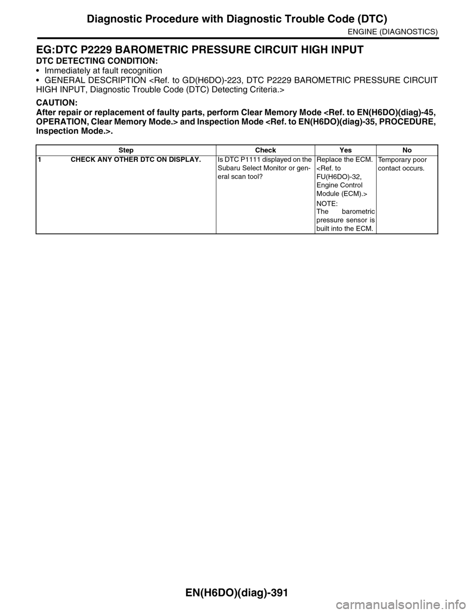
EG:DTC P2229 BAROMETRIC PRESSURE CIRCUIT HIGH INPUT
DTC DETECTING CONDITION:
•Immediately at fault recognition
•GENERAL DESCRIPTION
CAUTION:
After repair or replacement of faulty parts, perform Clear Memory Mode
Step Check Yes No
1CHECK ANY OTHER DTC ON DISPLAY.Is DTC P1111 displayed on the
Subaru Select Monitor or gen-
eral scan tool?
Replace the ECM.
Engine Control
Module (ECM).>
NOTE:
The barometric
pressure sensor is
built into the ECM.
Te m p o r a r y p o o r
contact occurs.
Page 1888 of 2453
ME(H6DO)-22
Idle Speed
MECHANICAL
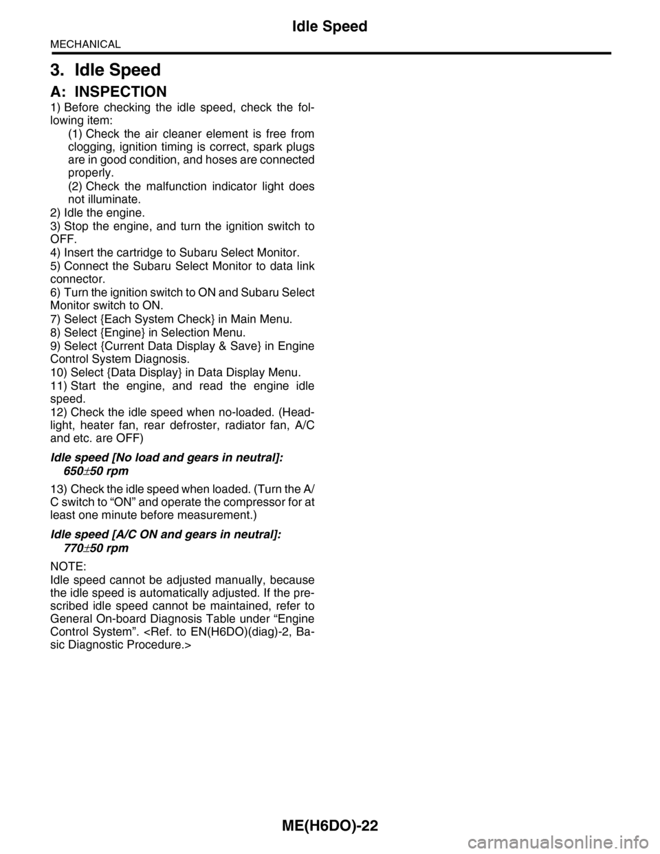
3. Idle Speed
A: INSPECTION
1) Before checking the idle speed, check the fol-
lowing item:
(1) Check the air cleaner element is free from
clogging, ignition timing is correct, spark plugs
are in good condition, and hoses are connected
properly.
(2) Check the malfunction indicator light does
not illuminate.
2) Idle the engine.
3) Stop the engine, and turn the ignition switch to
OFF.
4) Insert the cartridge to Subaru Select Monitor.
5) Connect the Subaru Select Monitor to data link
connector.
6) Turn the ignition switch to ON and Subaru Select
Monitor switch to ON.
7) Select {Each System Check} in Main Menu.
8) Select {Engine} in Selection Menu.
9) Select {Current Data Display & Save} in Engine
Control System Diagnosis.
10) Select {Data Display} in Data Display Menu.
11) Start the engine, and read the engine idle
speed.
12) Check the idle speed when no-loaded. (Head-
light, heater fan, rear defroster, radiator fan, A/C
and etc. are OFF)
Idle speed [No load and gears in neutral]:
650±50 rpm
13) Check the idle speed when loaded. (Turn the A/
C switch to “ON” and operate the compressor for at
least one minute before measurement.)
Idle speed [A/C ON and gears in neutral]:
770±50 rpm
NOTE:
Idle speed cannot be adjusted manually, because
the idle speed is automatically adjusted. If the pre-
scribed idle speed cannot be maintained, refer to
General On-board Diagnosis Table under “Engine
Control System”.
Page 1889 of 2453
ME(H6DO)-23
Ignition Timing
MECHANICAL
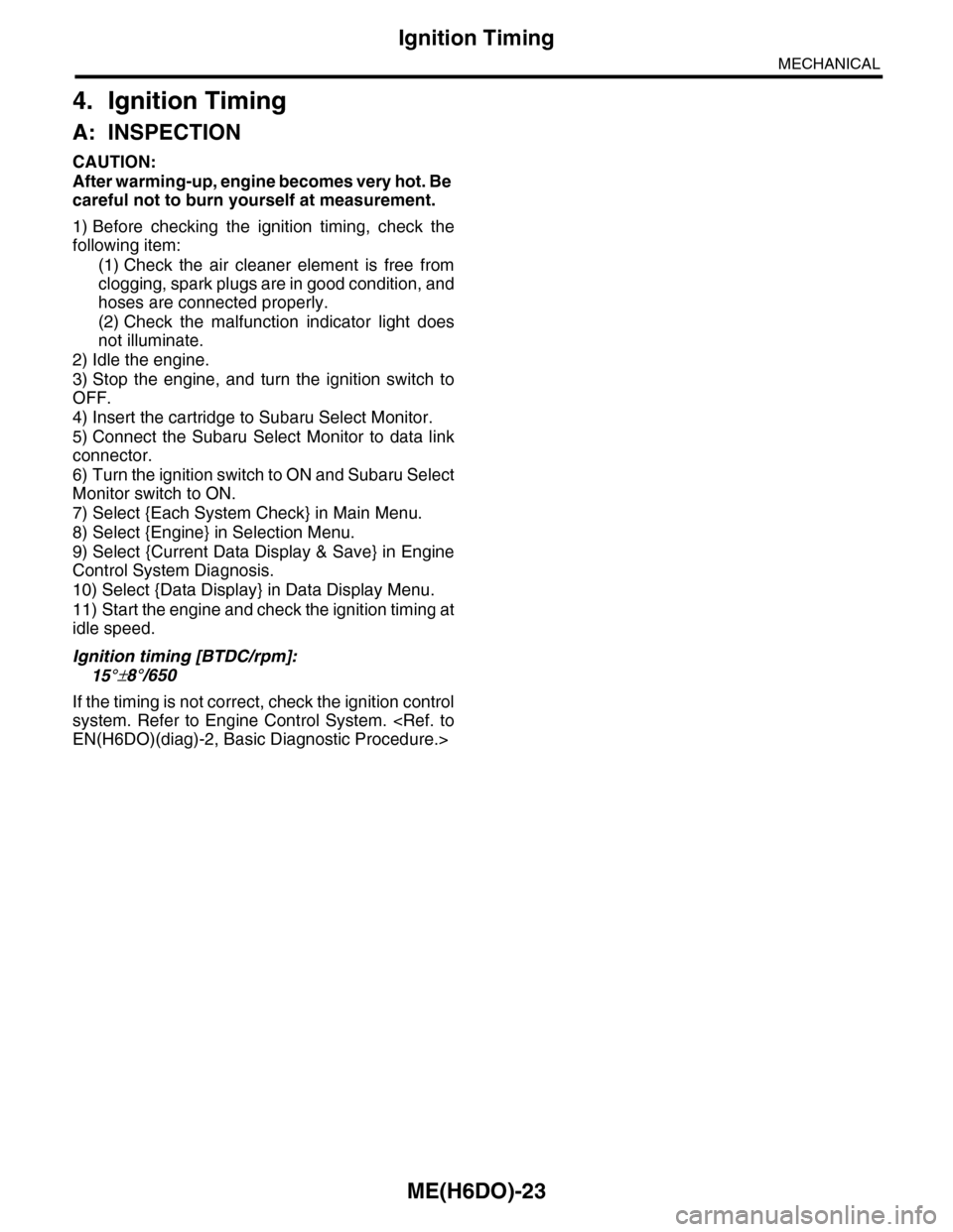
4. Ignition Timing
A: INSPECTION
CAUTION:
After warming-up, engine becomes very hot. Be
careful not to burn yourself at measurement.
1) Before checking the ignition timing, check the
following item:
(1) Check the air cleaner element is free from
clogging, spark plugs are in good condition, and
hoses are connected properly.
(2) Check the malfunction indicator light does
not illuminate.
2) Idle the engine.
3) Stop the engine, and turn the ignition switch to
OFF.
4) Insert the cartridge to Subaru Select Monitor.
5) Connect the Subaru Select Monitor to data link
connector.
6) Turn the ignition switch to ON and Subaru Select
Monitor switch to ON.
7) Select {Each System Check} in Main Menu.
8) Select {Engine} in Selection Menu.
9) Select {Current Data Display & Save} in Engine
Control System Diagnosis.
10) Select {Data Display} in Data Display Menu.
11) Start the engine and check the ignition timing at
idle speed.
Ignition timing [BTDC/rpm]:
15°±8°/650
If the timing is not correct, check the ignition control
system. Refer to Engine Control System.
Page 1939 of 2453
ME(H6DO)-73
Cylinder Block
MECHANICAL
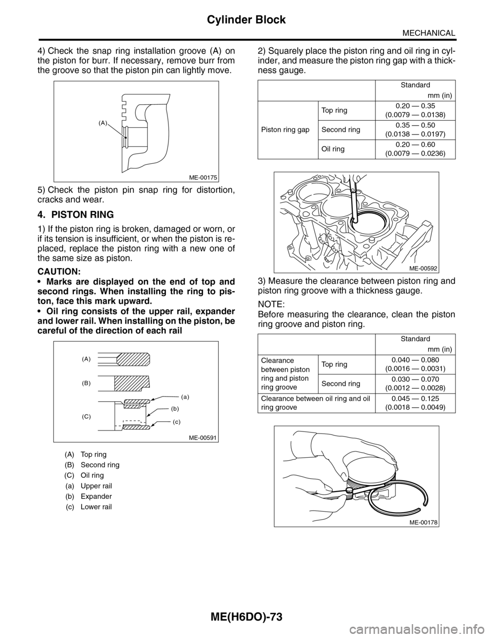
4) Check the snap ring installation groove (A) on
the piston for burr. If necessary, remove burr from
the groove so that the piston pin can lightly move.
5) Check the piston pin snap ring for distortion,
cracks and wear.
4. PISTON RING
1) If the piston ring is broken, damaged or worn, or
if its tension is insufficient, or when the piston is re-
placed, replace the piston ring with a new one of
the same size as piston.
CAUTION:
•Marks are displayed on the end of top and
second rings. When installing the ring to pis-
ton, face this mark upward.
•Oil ring consists of the upper rail, expander
and lower rail. When installing on the piston, be
careful of the direction of each rail
2) Squarely place the piston ring and oil ring in cyl-
inder, and measure the piston ring gap with a thick-
ness gauge.
3) Measure the clearance between piston ring and
piston ring groove with a thickness gauge.
NOTE:
Before measuring the clearance, clean the piston
ring groove and piston ring.
(A) Top ring
(B) Second ring
(C) Oil ring
(a) Upper rail
(b) Expander
(c) Lower rail
ME-00175
(A)
(a)
(c)
(b)
(A)
(B)
(C)
ME-00591
Standard
mm (in)
Piston ring gap
To p r i n g0.20 — 0.35
(0.0079 — 0.0138)
Second ring0.35 — 0.50
(0.0138 — 0.0197)
Oil ring0.20 — 0.60
(0.0079 — 0.0236)
Standard
mm (in)
Clearance
between piston
ring and piston
ring groove
To p r i n g0.040 — 0.080
(0.0016 — 0.0031)
Second ring0.030 — 0.070
(0.0012 — 0.0028)
Clearance between oil ring and oil
ring groove
0.045 — 0.125
(0.0018 — 0.0049)
ME-00592
ME-00178