2009 SUBARU TRIBECA display
[x] Cancel search: displayPage 2238 of 2453
5AT(diag)-121
Diagnostic Procedure without Diagnostic Trouble Code (DTC)
AUTOMATIC TRANSMISSION (DIAGNOSTICS)
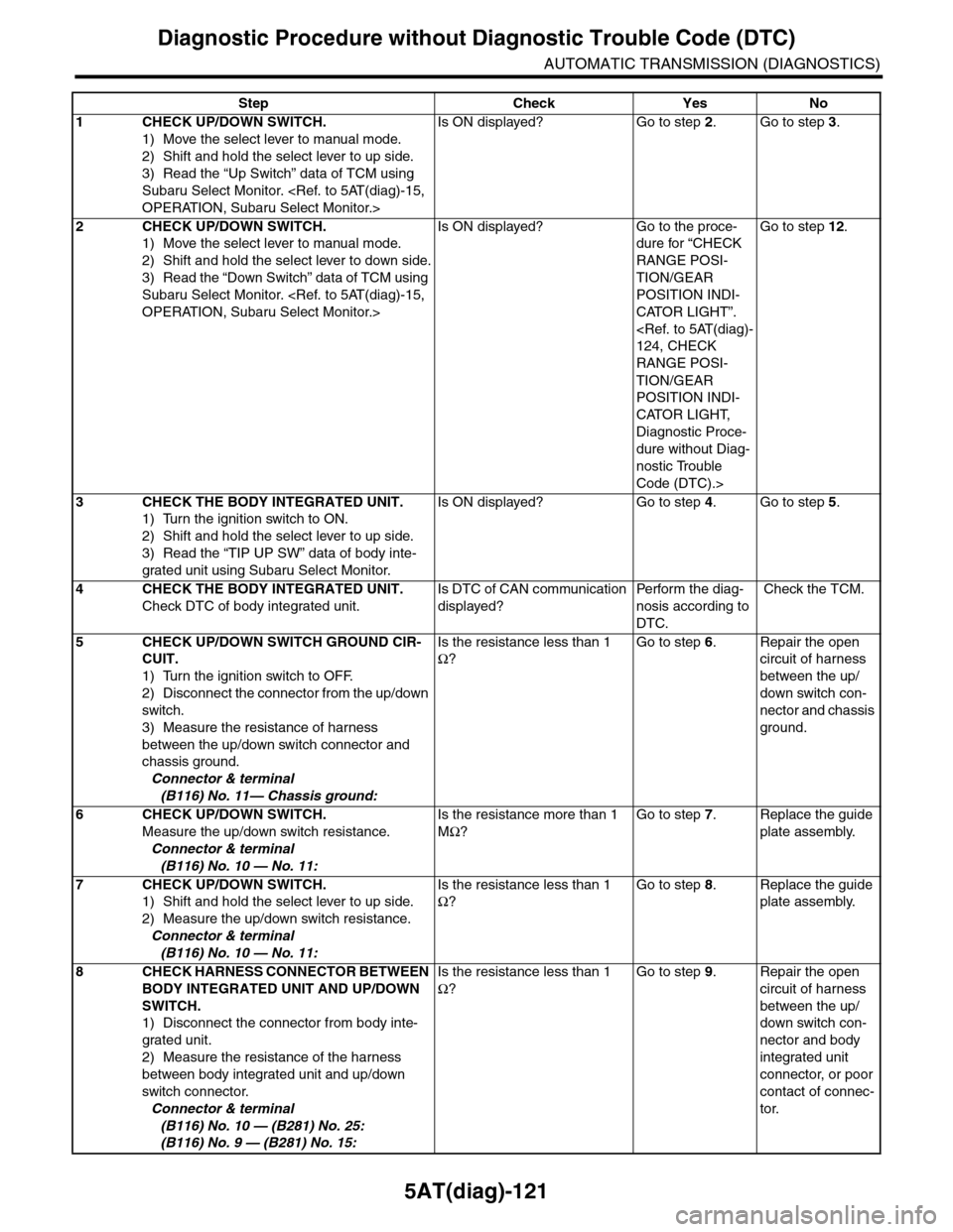
Step Check Yes No
1CHECK UP/DOWN SWITCH.
1) Move the select lever to manual mode.
2) Shift and hold the select lever to up side.
3) Read the “Up Switch” data of TCM using
Subaru Select Monitor.
Is ON displayed? Go to step 2.Go to step 3.
2CHECK UP/DOWN SWITCH.
1) Move the select lever to manual mode.
2) Shift and hold the select lever to down side.
3) Read the “Down Switch” data of TCM using
Subaru Select Monitor.
Is ON displayed? Go to the proce-
dure for “CHECK
RANGE POSI-
TION/GEAR
POSITION INDI-
CATOR LIGHT”.
RANGE POSI-
TION/GEAR
POSITION INDI-
CATOR LIGHT,
Diagnostic Proce-
dure without Diag-
nostic Trouble
Code (DTC).>
Go to step 12.
3CHECK THE BODY INTEGRATED UNIT.
1) Turn the ignition switch to ON.
2) Shift and hold the select lever to up side.
3) Read the “TIP UP SW” data of body inte-
grated unit using Subaru Select Monitor.
Is ON displayed? Go to step 4.Go to step 5.
4CHECK THE BODY INTEGRATED UNIT.
Check DTC of body integrated unit.
Is DTC of CAN communication
displayed?
Pe r for m t h e d ia g -
nosis according to
DTC.
Check the TCM.
5CHECK UP/DOWN SWITCH GROUND CIR-
CUIT.
1) Turn the ignition switch to OFF.
2) Disconnect the connector from the up/down
switch.
3) Measure the resistance of harness
between the up/down switch connector and
chassis ground.
Connector & terminal
(B116) No. 11— Chassis ground:
Is the resistance less than 1
Ω?
Go to step 6.Repair the open
circuit of harness
between the up/
down switch con-
nector and chassis
ground.
6CHECK UP/DOWN SWITCH.
Measure the up/down switch resistance.
Connector & terminal
(B116) No. 10 — No. 11:
Is the resistance more than 1
MΩ?
Go to step 7.Replace the guide
plate assembly.
7CHECK UP/DOWN SWITCH.
1) Shift and hold the select lever to up side.
2) Measure the up/down switch resistance.
Connector & terminal
(B116) No. 10 — No. 11:
Is the resistance less than 1
Ω?
Go to step 8.Replace the guide
plate assembly.
8CHECK HARNESS CONNECTOR BETWEEN
BODY INTEGRATED UNIT AND UP/DOWN
SWITCH.
1) Disconnect the connector from body inte-
grated unit.
2) Measure the resistance of the harness
between body integrated unit and up/down
switch connector.
Connector & terminal
(B116) No. 10 — (B281) No. 25:
(B116) No. 9 — (B281) No. 15:
Is the resistance less than 1
Ω?
Go to step 9.Repair the open
circuit of harness
between the up/
down switch con-
nector and body
integrated unit
connector, or poor
contact of connec-
tor.
Page 2239 of 2453
5AT(diag)-122
Diagnostic Procedure without Diagnostic Trouble Code (DTC)
AUTOMATIC TRANSMISSION (DIAGNOSTICS)
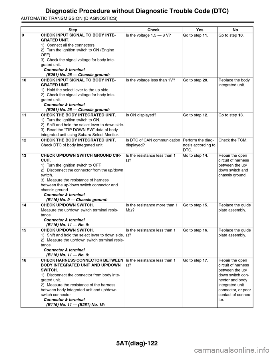
9CHECK INPUT SIGNAL TO BODY INTE-
GRATED UNIT.
1) Connect all the connectors.
2) Turn the ignition switch to ON (Engine
OFF).
3) Check the signal voltage for body inte-
grated unit.
Connector & terminal
(B281) No. 25 — Chassis ground:
Is the voltage 1.5 — 8 V? Go to step 11.Go to step 10.
10 CHECK INPUT SIGNAL TO BODY INTE-
GRATED UNIT.
1) Hold the select lever to the up side.
2) Check the signal voltage for body inte-
grated unit.
Connector & terminal
(B281) No. 25 — Chassis ground:
Is the voltage less than 1V? Go to step 20.Replace the body
integrated unit.
11 CHECK THE BODY INTEGRATED UNIT.
1) Turn the ignition switch to ON.
2) Shift and hold the select lever to down side.
3) Read the “TIP DOWN SW” data of body
integrated unit using Subaru Select Monitor.
Is ON displayed? Go to step 12.Go to step 13.
12 CHECK THE BODY INTEGRATED UNIT.
Check DTC of body integrated unit.
Is DTC of CAN communication
displayed?
Pe r for m t h e d ia g -
nosis according to
DTC.
Check the TCM.
13 CHECK UP/DOWN SWITCH GROUND CIR-
CUIT.
1) Turn the ignition switch to OFF.
2) Disconnect the connector from the up/down
switch.
3) Measure the resistance of harness
between the up/down switch connector and
chassis ground.
Connector & terminal
(B116) No. 9 — Chassis ground:
Is the resistance less than 1
Ω?
Go to step 14.Repair the open
circuit of harness
between the up/
down switch and
chassis ground.
14 CHECK UP/DOWN SWITCH.
Measure the up/down switch terminal resis-
tance.
Connector & terminal
(B116) No. 11 — No. 9:
Is the resistance more than 1
MΩ?
Go to step 15.Replace the guide
plate assembly.
15 CHECK UP/DOWN SWITCH.
1) Shift and hold the select lever to down side.
2) Measure the up/down switch terminal resis-
tance.
Connector & terminal
(B116) No. 11 — No. 9:
Is the resistance less than 1
Ω?
Go to step 16.Replace the guide
plate assembly.
16 CHECK HARNESS CONNECTOR BETWEEN
BODY INTEGRATED UNIT AND UP/DOWN
SWITCH.
1) Disconnect the connector from body inte-
grated unit.
2) Measure the resistance of the harness
between body integrated unit and up/down
switch connector.
Connector & terminal
(B116) No. 11 — (B281) No. 15:
Is the resistance less than 1
Ω?
Go to step 17.Repair the open
circuit of harness
between the up/
down switch con-
nector and body
integrated unit
connector, or poor
contact of connec-
tor.
Step Check Yes No
Page 2241 of 2453
5AT(diag)-124
Diagnostic Procedure without Diagnostic Trouble Code (DTC)
AUTOMATIC TRANSMISSION (DIAGNOSTICS)
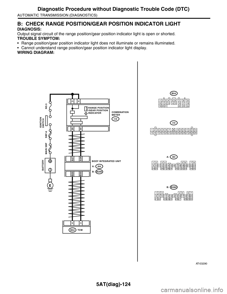
B: CHECK RANGE POSITION/GEAR POSITION INDICATOR LIGHT
DIAGNOSIS:
Output signal circuit of the range position/gear position indicator light is open or shorted.
TROUBLE SYMPTOM:
•Range position/gear position indicator light does not illuminate or remains illuminated.
•Cannot understand range position/gear position indicator light display.
WIRING DIAGRAM:
AT-03290
34
2930
COMBINATIONMETER
i10
A27A26
B20B30
BODY INTEGRATED UNIT
i84A:
B280B:
43
TCMB54
BATTERY
MAIN SBF SBF-6 NO.5
E
IGNITIONSWITCH
i84
8765432122232120191615141312111093435333217301831292827262524
A:
B54
12789563410 11 1219 20 2113 14 15 16 17 18222324
B280
87654321
2223212019161514131211109173018292827262524
B:
i10
123456789101112131415161718192021222324252627282930
RANGE POSITION/GEAR POSITIONINDICATOR
Page 2242 of 2453
5AT(diag)-125
Diagnostic Procedure without Diagnostic Trouble Code (DTC)
AUTOMATIC TRANSMISSION (DIAGNOSTICS)
Step Check Yes No
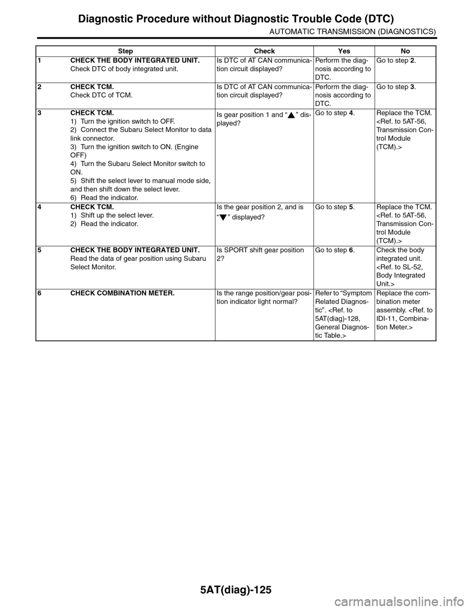
1CHECK THE BODY INTEGRATED UNIT.
Check DTC of body integrated unit.
Is DTC of AT CAN communica-
tion circuit displayed?
Pe r for m t h e d ia g -
nosis according to
DTC.
Go to step 2.
2CHECK TCM.
Check DTC of TCM.
Is DTC of AT CAN communica-
tion circuit displayed?
Pe r for m t h e d ia g -
nosis according to
DTC.
Go to step 3.
3CHECK TCM.
1) Turn the ignition switch to OFF.
2) Connect the Subaru Select Monitor to data
link connector.
3) Turn the ignition switch to ON. (Engine
OFF)
4) Turn the Subaru Select Monitor switch to
ON.
5) Shift the select lever to manual mode side,
and then shift down the select lever.
6) Read the indicator.
Is gear position 1 and “ ” dis-
played?
Go to step 4.Replace the TCM.
trol Module
(TCM).>
4CHECK TCM.
1) Shift up the select lever.
2) Read the indicator.
Is the gear position 2, and is
“” displayed?
Go to step 5.Replace the TCM.
trol Module
(TCM).>
5CHECK THE BODY INTEGRATED UNIT.
Read the data of gear position using Subaru
Select Monitor.
Is SPORT shift gear position
2?
Go to step 6.Check the body
integrated unit.
Unit.>
6CHECK COMBINATION METER.Is the range position/gear posi-
tion indicator light normal?
Refer to “Symptom
Related Diagnos-
tic”.
General Diagnos-
tic Table.>
Replace the com-
bination meter
assembly.
tion Meter.>
Page 2244 of 2453
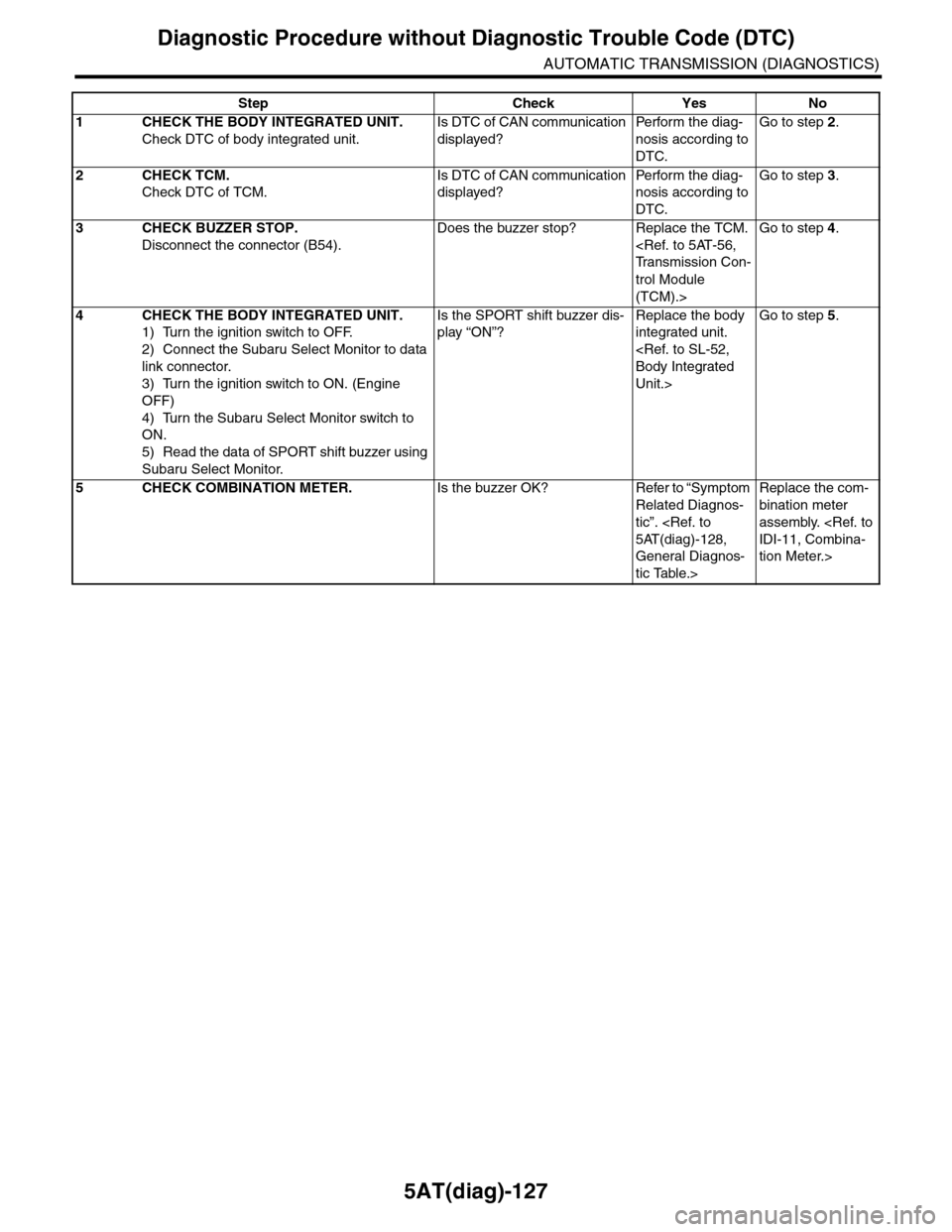
5AT(diag)-127
Diagnostic Procedure without Diagnostic Trouble Code (DTC)
AUTOMATIC TRANSMISSION (DIAGNOSTICS)
Step Check Yes No
1CHECK THE BODY INTEGRATED UNIT.
Check DTC of body integrated unit.
Is DTC of CAN communication
displayed?
Pe r for m t h e d ia g -
nosis according to
DTC.
Go to step 2.
2CHECK TCM.
Check DTC of TCM.
Is DTC of CAN communication
displayed?
Pe r for m t h e d ia g -
nosis according to
DTC.
Go to step 3.
3CHECK BUZZER STOP.
Disconnect the connector (B54).
Does the buzzer stop? Replace the TCM.
trol Module
(TCM).>
Go to step 4.
4CHECK THE BODY INTEGRATED UNIT.
1) Turn the ignition switch to OFF.
2) Connect the Subaru Select Monitor to data
link connector.
3) Turn the ignition switch to ON. (Engine
OFF)
4) Turn the Subaru Select Monitor switch to
ON.
5) Read the data of SPORT shift buzzer using
Subaru Select Monitor.
Is the SPORT shift buzzer dis-
play “ON”?
Replace the body
integrated unit.
Unit.>
Go to step 5.
5CHECK COMBINATION METER.Is the buzzer OK? Refer to “Symptom
Related Diagnos-
tic”.
General Diagnos-
tic Table.>
Replace the com-
bination meter
assembly.
tion Meter.>
Page 2265 of 2453
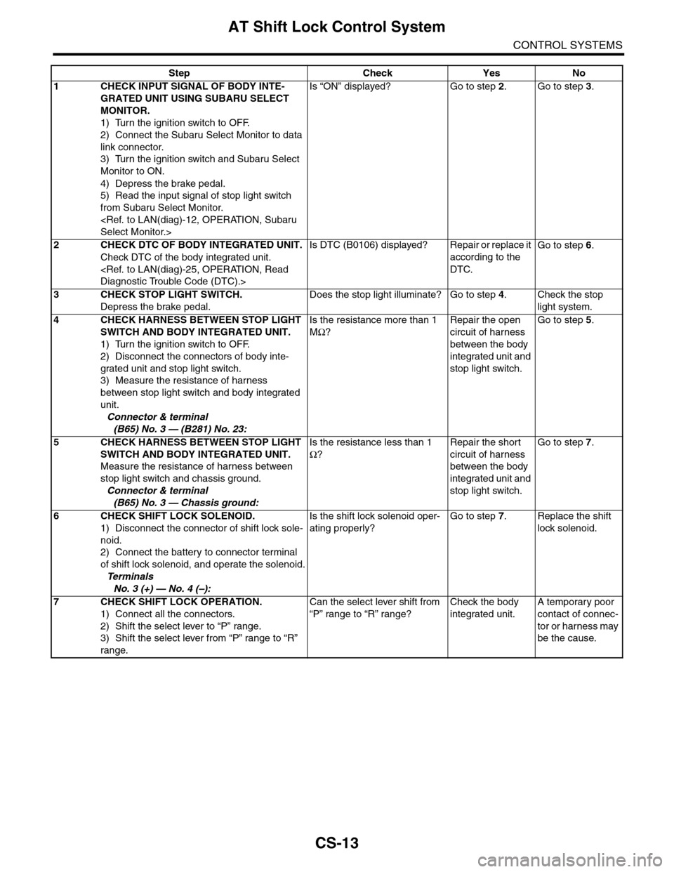
CS-13
AT Shift Lock Control System
CONTROL SYSTEMS
Step Check Yes No
1CHECK INPUT SIGNAL OF BODY INTE-
GRATED UNIT USING SUBARU SELECT
MONITOR.
1) Turn the ignition switch to OFF.
2) Connect the Subaru Select Monitor to data
link connector.
3) Turn the ignition switch and Subaru Select
Monitor to ON.
4) Depress the brake pedal.
5) Read the input signal of stop light switch
from Subaru Select Monitor.
Is “ON” displayed? Go to step 2.Go to step 3.
2CHECK DTC OF BODY INTEGRATED UNIT.
Check DTC of the body integrated unit.
Is DTC (B0106) displayed? Repair or replace it
according to the
DTC.
Go to step 6.
3CHECK STOP LIGHT SWITCH.
Depress the brake pedal.
Does the stop light illuminate? Go to step 4.Check the stop
light system.
4CHECK HARNESS BETWEEN STOP LIGHT
SWITCH AND BODY INTEGRATED UNIT.
1) Turn the ignition switch to OFF.
2) Disconnect the connectors of body inte-
grated unit and stop light switch.
3) Measure the resistance of harness
between stop light switch and body integrated
unit.
Connector & terminal
(B65) No. 3 — (B281) No. 23:
Is the resistance more than 1
MΩ?
Repair the open
circuit of harness
between the body
integrated unit and
stop light switch.
Go to step 5.
5CHECK HARNESS BETWEEN STOP LIGHT
SWITCH AND BODY INTEGRATED UNIT.
Measure the resistance of harness between
stop light switch and chassis ground.
Connector & terminal
(B65) No. 3 — Chassis ground:
Is the resistance less than 1
Ω?
Repair the short
circuit of harness
between the body
integrated unit and
stop light switch.
Go to step 7.
6CHECK SHIFT LOCK SOLENOID.
1) Disconnect the connector of shift lock sole-
noid.
2) Connect the battery to connector terminal
of shift lock solenoid, and operate the solenoid.
Te r m i n a l s
No. 3 (+) — No. 4 (–):
Is the shift lock solenoid oper-
ating properly?
Go to step 7.Replace the shift
lock solenoid.
7CHECK SHIFT LOCK OPERATION.
1) Connect all the connectors.
2) Shift the select lever to “P” range.
3) Shift the select lever from “P” range to “R”
range.
Can the select lever shift from
“P” range to “R” range?
Check the body
integrated unit.
A temporary poor
contact of connec-
tor or harness may
be the cause.
Page 2267 of 2453
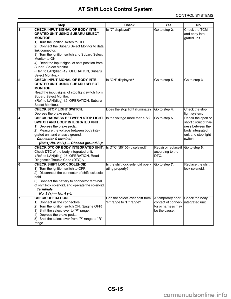
CS-15
AT Shift Lock Control System
CONTROL SYSTEMS
Step Check Yes No
1CHECK INPUT SIGNAL OF BODY INTE-
GRATED UNIT USING SUBARU SELECT
MONITOR.
1) Turn the ignition switch to OFF.
2) Connect the Subaru Select Monitor to data
link connector.
3) Turn the ignition switch and Subaru Select
Monitor to ON.
4) Read the input signal of shift position from
Subaru Select Monitor.
Is “7” displayed? Go to step 2.Check the TCM
and body inte-
grated unit.
2CHECK INPUT SIGNAL OF BODY INTE-
GRATED UNIT USING SUBARU SELECT
MONITOR.
Read the input signal of stop light switch from
Subaru Select Monitor.
Is “ON” displayed? Go to step 5.Go to step 3.
3CHECK STOP LIGHT SWITCH.
Depress the brake pedal.
Does the stop light illuminate? Go to step 4.Check the stop
light system.
4CHECK HARNESS BETWEEN STOP LIGHT
SWITCH AND BODY INTEGRATED UNIT.
1) Depress the brake pedal.
2) Measure the voltage between body inte-
grated unit and chassis ground.
Connector & terminal
(B281) No. 23 (+) — Chassis ground (–):
Is the voltage more than 9 V? Go to step 5.Repair the open or
short circuit of har-
ness between the
body integrated
unit and stop light
switch.
5CHECK DTC OF BODY INTEGRATED UNIT.
Check DTC of the body integrated unit.
Is DTC (B0106) displayed? Repair or replace it
according to the
DTC.
Go to step 6.
6CHECK SHIFT LOCK SOLENOID.
1) Turn the ignition switch to OFF.
2) Disconnect the connector of shift lock sole-
noid.
3) Connect the battery to connector terminal
of shift lock solenoid, and operate the solenoid.
Te r m i n a l s
No. 3 (+) — No. 4 (–):
Is the shift lock solenoid oper-
ating properly?
Go to step 7.Replace the shift
lock solenoid.
7CHECK OPERATION.
1) Connect all the connectors.
2) Turn the ignition switch ON. (Engine OFF)
3) Shift the select lever to “P” range.
4) Depress the brake pedal.
5) Shift the select lever from “P” range to “R”
range.
Can the select lever shift from
“P” range to “R” range?
A temporary poor
contact of connec-
tor or harness may
be the cause.
Check the body
integrated unit.
Page 2269 of 2453
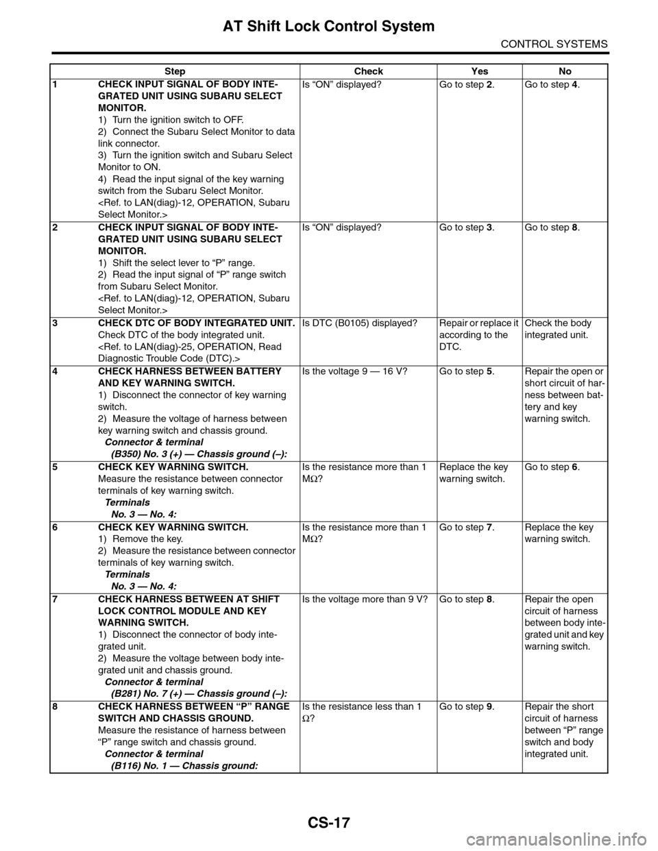
CS-17
AT Shift Lock Control System
CONTROL SYSTEMS
Step Check Yes No
1CHECK INPUT SIGNAL OF BODY INTE-
GRATED UNIT USING SUBARU SELECT
MONITOR.
1) Turn the ignition switch to OFF.
2) Connect the Subaru Select Monitor to data
link connector.
3) Turn the ignition switch and Subaru Select
Monitor to ON.
4) Read the input signal of the key warning
switch from the Subaru Select Monitor.
Is “ON” displayed? Go to step 2.Go to step 4.
2CHECK INPUT SIGNAL OF BODY INTE-
GRATED UNIT USING SUBARU SELECT
MONITOR.
1) Shift the select lever to “P” range.
2) Read the input signal of “P” range switch
from Subaru Select Monitor.
Is “ON” displayed? Go to step 3.Go to step 8.
3CHECK DTC OF BODY INTEGRATED UNIT.
Check DTC of the body integrated unit.
Is DTC (B0105) displayed? Repair or replace it
according to the
DTC.
Check the body
integrated unit.
4CHECK HARNESS BETWEEN BATTERY
AND KEY WARNING SWITCH.
1) Disconnect the connector of key warning
switch.
2) Measure the voltage of harness between
key warning switch and chassis ground.
Connector & terminal
(B350) No. 3 (+) — Chassis ground (–):
Is the voltage 9 — 16 V? Go to step 5.Repair the open or
short circuit of har-
ness between bat-
tery and key
warning switch.
5 CHECK KEY WARNING SWITCH.
Measure the resistance between connector
terminals of key warning switch.
Te r m i n a l s
No. 3 — No. 4:
Is the resistance more than 1
MΩ?
Replace the key
warning switch.
Go to step 6.
6 CHECK KEY WARNING SWITCH.
1) Remove the key.
2) Measure the resistance between connector
terminals of key warning switch.
Te r m i n a l s
No. 3 — No. 4:
Is the resistance more than 1
MΩ?
Go to step 7.Replace the key
warning switch.
7CHECK HARNESS BETWEEN AT SHIFT
LOCK CONTROL MODULE AND KEY
WARNING SWITCH.
1) Disconnect the connector of body inte-
grated unit.
2) Measure the voltage between body inte-
grated unit and chassis ground.
Connector & terminal
(B281) No. 7 (+) — Chassis ground (–):
Is the voltage more than 9 V? Go to step 8.Repair the open
circuit of harness
between body inte-
grated unit and key
warning switch.
8CHECK HARNESS BETWEEN “P” RANGE
SWITCH AND CHASSIS GROUND.
Measure the resistance of harness between
“P” range switch and chassis ground.
Connector & terminal
(B116) No. 1 — Chassis ground:
Is the resistance less than 1
Ω?
Go to step 9.Repair the short
circuit of harness
between “P” range
switch and body
integrated unit.