2009 SUBARU TRIBECA er ss displayed
[x] Cancel search: er ss displayedPage 1057 of 2453
VDC(diag)-65
Diagnostic Procedure with Diagnostic Trouble Code (DTC)
VEHICLE DYNAMICS CONTROL (VDC) (DIAGNOSTICS)
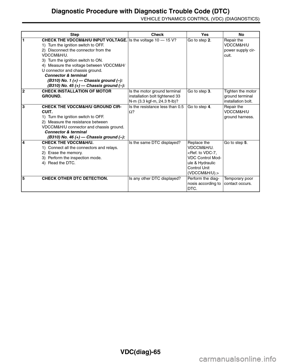
Step Check Yes No
1CHECK THE VDCCM&H/U INPUT VOLTAGE.
1) Turn the ignition switch to OFF.
2) Disconnect the connector from the
VDCCM&H/U.
3) Turn the ignition switch to ON.
4) Measure the voltage between VDCCM&H/
U connector and chassis ground.
Connector & terminal
(B310) No. 1 (+) — Chassis ground (–):
(B310) No. 45 (+) — Chassis ground (–):
Is the voltage 10 — 15 V? Go to step 2.Repair the
VDCCM&H/U
power supply cir-
cuit.
2CHECK INSTALLATION OF MOTOR
GROUND.
Is the motor ground terminal
installation bolt tightened 33
N·m (3.3 kgf-m, 24.3 ft-lb)?
Go to step 3.Tighten the motor
ground terminal
installation bolt.
3CHECK THE VDCCM&H/U GROUND CIR-
CUIT.
1) Turn the ignition switch to OFF.
2) Measure the resistance between
VDCCM&H/U connector and chassis ground.
Connector & terminal
(B310) No. 46 (+) — Chassis ground (–):
Is the resistance less than 0.5
Ω?
Go to step 4.Repair the
VDCCM&H/U
ground harness.
4CHECK THE VDCCM&H/U.
1) Connect all the connectors and relays.
2) Erase the memory.
3) Perform the inspection mode.
4) Read the DTC.
Is the same DTC displayed? Replace the
VDCCM&H/U.
ule & Hydraulic
Control Unit
(VDCCM&H/U).>
Go to step 5.
5CHECK OTHER DTC DETECTION.Is any other DTC displayed? Perform the diag-
nosis according to
DTC.
Te m p o r a r y p o o r
contact occurs.
Page 1059 of 2453
VDC(diag)-67
Diagnostic Procedure with Diagnostic Trouble Code (DTC)
VEHICLE DYNAMICS CONTROL (VDC) (DIAGNOSTICS)
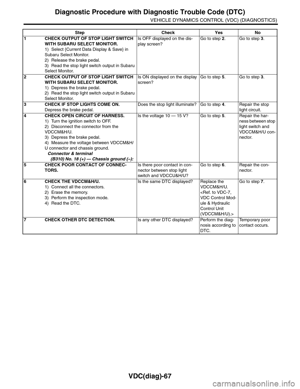
Step Check Yes No
1CHECK OUTPUT OF STOP LIGHT SWITCH
WITH SUBARU SELECT MONITOR.
1) Select {Current Data Display & Save} in
Subaru Select Monitor.
2) Release the brake pedal.
3) Read the stop light switch output in Subaru
Select Monitor.
Is OFF displayed on the dis-
play screen?
Go to step 2.Go to step 3.
2CHECK OUTPUT OF STOP LIGHT SWITCH
WITH SUBARU SELECT MONITOR.
1) Depress the brake pedal.
2) Read the stop light switch output in Subaru
Select Monitor.
Is ON displayed on the display
screen?
Go to step 5.Go to step 3.
3CHECK IF STOP LIGHTS COME ON.
Depress the brake pedal.
Does the stop light illuminate? Go to step 4.Repair the stop
light circuit.
4CHECK OPEN CIRCUIT OF HARNESS.
1) Turn the ignition switch to OFF.
2) Disconnect the connector from the
VDCCM&H/U.
3) Depress the brake pedal.
4) Measure the voltage between VDCCM&H/
U connector and chassis ground.
Connector & terminal
(B310) No. 18 (+) — Chassis ground (–):
Is the voltage 10 — 15 V? Go to step 5.Repair the har-
ness between stop
light switch and
VDCCM&H/U con-
nector.
5CHECK POOR CONTACT OF CONNEC-
TORS.
Is there poor contact in con-
nector between stop light
switch and VDCCU&H/U?
Go to step 6.Repair the con-
nector.
6CHECK THE VDCCM&H/U.
1) Connect all the connectors.
2) Erase the memory.
3) Perform the inspection mode.
4) Read the DTC.
Is the same DTC displayed? Replace the
VDCCM&H/U.
ule & Hydraulic
Control Unit
(VDCCM&H/U).>
Go to step 7.
7CHECK OTHER DTC DETECTION.Is any other DTC displayed? Perform the diag-
nosis according to
DTC.
Te m p o r a r y p o o r
contact occurs.
Page 1060 of 2453
VDC(diag)-68
Diagnostic Procedure with Diagnostic Trouble Code (DTC)
VEHICLE DYNAMICS CONTROL (VDC) (DIAGNOSTICS)
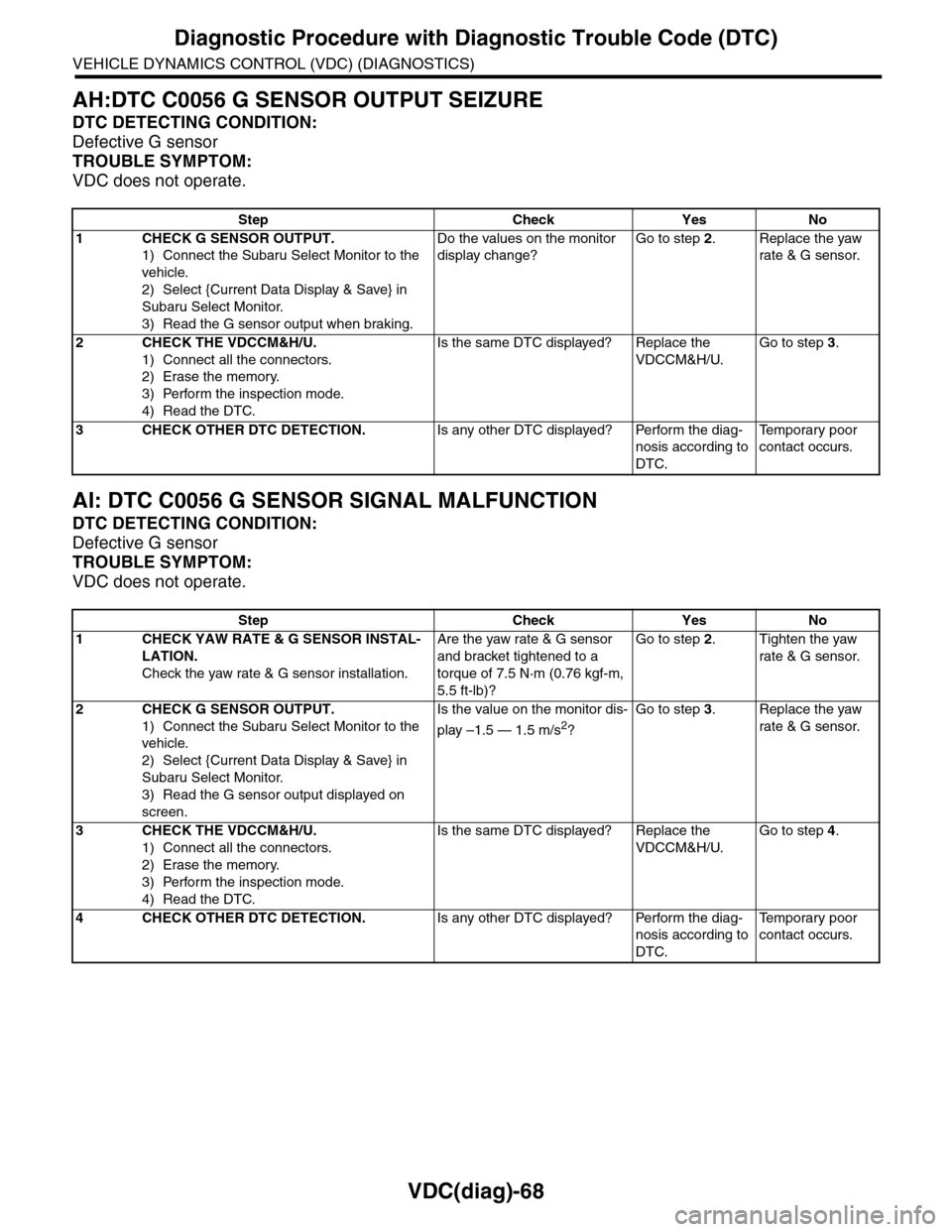
AH:DTC C0056 G SENSOR OUTPUT SEIZURE
DTC DETECTING CONDITION:
Defective G sensor
TROUBLE SYMPTOM:
VDC does not operate.
AI: DTC C0056 G SENSOR SIGNAL MALFUNCTION
DTC DETECTING CONDITION:
Defective G sensor
TROUBLE SYMPTOM:
VDC does not operate.
Step Check Yes No
1CHECK G SENSOR OUTPUT.
1) Connect the Subaru Select Monitor to the
vehicle.
2) Select {Current Data Display & Save} in
Subaru Select Monitor.
3) Read the G sensor output when braking.
Do the values on the monitor
display change?
Go to step 2.Replace the yaw
rate & G sensor.
2CHECK THE VDCCM&H/U.
1) Connect all the connectors.
2) Erase the memory.
3) Perform the inspection mode.
4) Read the DTC.
Is the same DTC displayed? Replace the
VDCCM&H/U.
Go to step 3.
3CHECK OTHER DTC DETECTION.Is any other DTC displayed? Perform the diag-
nosis according to
DTC.
Te m p o r a r y p o o r
contact occurs.
Step Check Yes No
1CHECK YAW RATE & G SENSOR INSTAL-
LATION.
Check the yaw rate & G sensor installation.
Are the yaw rate & G sensor
and bracket tightened to a
torque of 7.5 N·m (0.76 kgf-m,
5.5 ft-lb)?
Go to step 2.Tighten the yaw
rate & G sensor.
2CHECK G SENSOR OUTPUT.
1) Connect the Subaru Select Monitor to the
vehicle.
2) Select {Current Data Display & Save} in
Subaru Select Monitor.
3) Read the G sensor output displayed on
screen.
Is the value on the monitor dis-
play –1.5 — 1.5 m/s2?
Go to step 3.Replace the yaw
rate & G sensor.
3CHECK THE VDCCM&H/U.
1) Connect all the connectors.
2) Erase the memory.
3) Perform the inspection mode.
4) Read the DTC.
Is the same DTC displayed? Replace the
VDCCM&H/U.
Go to step 4.
4CHECK OTHER DTC DETECTION.Is any other DTC displayed? Perform the diag-
nosis according to
DTC.
Te m p o r a r y p o o r
contact occurs.
Page 1062 of 2453
VDC(diag)-70
Diagnostic Procedure with Diagnostic Trouble Code (DTC)
VEHICLE DYNAMICS CONTROL (VDC) (DIAGNOSTICS)
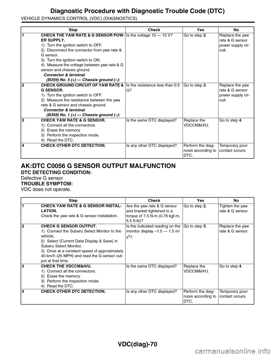
AK:DTC C0056 G SENSOR OUTPUT MALFUNCTION
DTC DETECTING CONDITION:
Defective G sensor
TROUBLE SYMPTOM:
VDC does not operate.
Step Check Yes No
1CHECK THE YAW RATE & G SENSOR POW-
ER SUPPLY.
1) Turn the ignition switch to OFF.
2) Disconnect the connector from yaw rate &
G sensor.
3) Turn the ignition switch to ON.
4) Measure the voltage between yaw rate & G
sensor and chassis ground.
Connector & terminal
(B359) No. 5 (+) — Chassis ground (–):
Is the voltage 10 — 15 V? Go to step 2.Replace the yaw
rate & G sensor
power supply cir-
cuit.
2CHECK GROUND CIRCUIT OF YAW RATE &
G SENSOR.
1) Turn the ignition switch to OFF.
2) Measure the resistance between the yaw
rate & G sensor and chassis ground.
Connector & terminal
(B359) No. 1 (+) — Chassis ground (–):
Is the resistance less than 0.5
Ω?
Go to step 3.Replace the yaw
rate & G sensor
power supply cir-
cuit.
3CHECK YAW RATE & G SENSOR.
1) Connect all the connectors.
2) Erase the memory.
3) Perform the inspection mode.
4) Read the DTC.
Is the same DTC displayed? Replace the
VDCCM&H/U.
Go to step 4.
4CHECK OTHER DTC DETECTION.Is any other DTC displayed? Perform the diag-
nosis according to
DTC.
Te m p o r a r y p o o r
contact occurs.
Step Check Yes No
1CHECK YAW RATE & G SENSOR INSTAL-
LATION.
Check the yaw rate & G sensor installation.
Are the yaw rate & G sensor
and bracket tightened to a
torque of 7.5 N·m (0.76 kgf-m,
5.5 ft-lb)?
Go to step 2.Tighten the yaw
rate & G sensor.
2CHECK G SENSOR OUTPUT.
1) Connect the Subaru Select Monitor to the
vehicle.
2) Select {Current Data Display & Save} in
Subaru Select Monitor.
3) Drive at a constant speed of approximately
40 km/h (25 MPH) and read the G sensor out-
put at that time.
Is the indicated reading on the
monitor display –1.5 — 1.5 m/
s2?
Go to step 3.Replace the yaw
rate & G sensor.
3CHECK THE VDCCM&H/U.
1) Connect all the connectors.
2) Erase the memory.
3) Perform the inspection mode.
4) Read the DTC.
Is the same DTC displayed? Replace the
VDCCM&H/U.
Go to step 4.
4CHECK OTHER DTC DETECTION.Is any other DTC displayed? Perform the diag-
nosis according to
DTC.
Te m p o r a r y p o o r
contact occurs.
Page 1063 of 2453
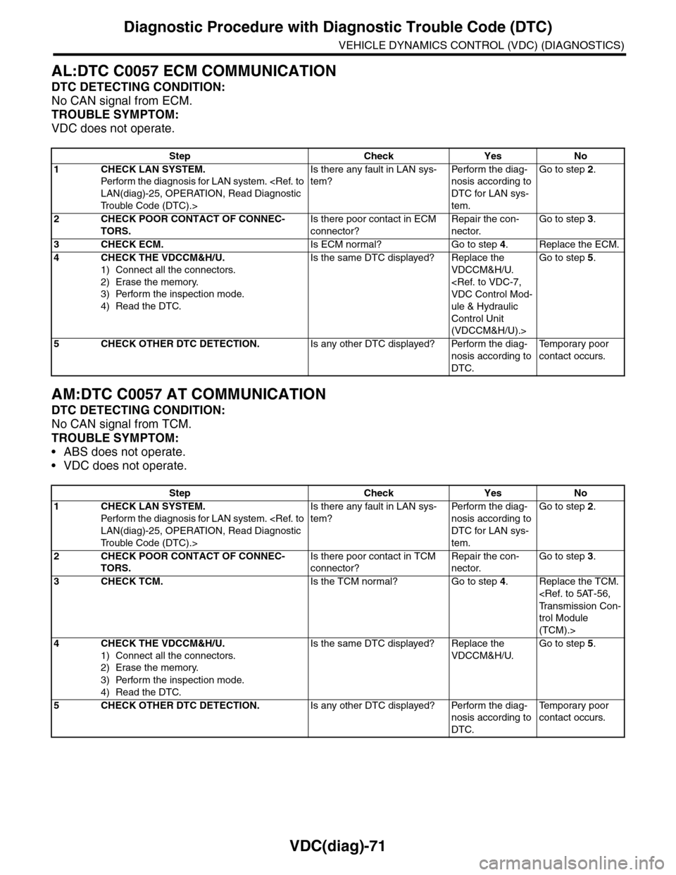
VDC(diag)-71
Diagnostic Procedure with Diagnostic Trouble Code (DTC)
VEHICLE DYNAMICS CONTROL (VDC) (DIAGNOSTICS)
AL:DTC C0057 ECM COMMUNICATION
DTC DETECTING CONDITION:
No CAN signal from ECM.
TROUBLE SYMPTOM:
VDC does not operate.
AM:DTC C0057 AT COMMUNICATION
DTC DETECTING CONDITION:
No CAN signal from TCM.
TROUBLE SYMPTOM:
•ABS does not operate.
•VDC does not operate.
Step Check Yes No
1CHECK LAN SYSTEM.
Perfor m the diagnosis for LAN system.
Tr o u b l e C o d e ( D T C ) . >
Is there any fault in LAN sys-
tem?
Pe r for m t h e d ia g -
nosis according to
DTC for LAN sys-
tem.
Go to step 2.
2CHECK POOR CONTACT OF CONNEC-
TORS.
Is there poor contact in ECM
connector?
Repair the con-
nector.
Go to step 3.
3CHECK ECM.Is ECM normal? Go to step 4.Replace the ECM.
4CHECK THE VDCCM&H/U.
1) Connect all the connectors.
2) Erase the memory.
3) Perform the inspection mode.
4) Read the DTC.
Is the same DTC displayed? Replace the
VDCCM&H/U.
ule & Hydraulic
Control Unit
(VDCCM&H/U).>
Go to step 5.
5CHECK OTHER DTC DETECTION.Is any other DTC displayed? Perform the diag-
nosis according to
DTC.
Te m p o r a r y p o o r
contact occurs.
Step Check Yes No
1CHECK LAN SYSTEM.
Perfor m the diagnosis for LAN system.
Tr o u b l e C o d e ( D T C ) . >
Is there any fault in LAN sys-
tem?
Pe r for m t h e d ia g -
nosis according to
DTC for LAN sys-
tem.
Go to step 2.
2CHECK POOR CONTACT OF CONNEC-
TORS.
Is there poor contact in TCM
connector?
Repair the con-
nector.
Go to step 3.
3CHECK TCM.Is the TCM normal? Go to step 4.Replace the TCM.
trol Module
(TCM).>
4CHECK THE VDCCM&H/U.
1) Connect all the connectors.
2) Erase the memory.
3) Perform the inspection mode.
4) Read the DTC.
Is the same DTC displayed? Replace the
VDCCM&H/U.
Go to step 5.
5CHECK OTHER DTC DETECTION.Is any other DTC displayed? Perform the diag-
nosis according to
DTC.
Te m p o r a r y p o o r
contact occurs.
Page 1064 of 2453
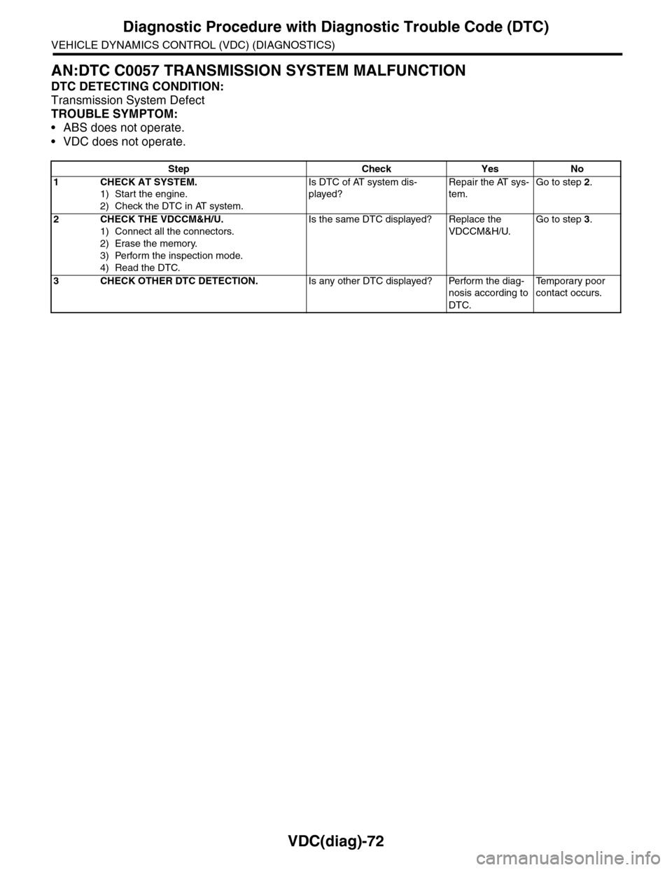
VDC(diag)-72
Diagnostic Procedure with Diagnostic Trouble Code (DTC)
VEHICLE DYNAMICS CONTROL (VDC) (DIAGNOSTICS)
AN:DTC C0057 TRANSMISSION SYSTEM MALFUNCTION
DTC DETECTING CONDITION:
Transmission System Defect
TROUBLE SYMPTOM:
•ABS does not operate.
•VDC does not operate.
Step Check Yes No
1CHECK AT SYSTEM.
1) Start the engine.
2) Check the DTC in AT system.
Is DTC of AT system dis-
played?
Repair the AT sys-
tem.
Go to step 2.
2CHECK THE VDCCM&H/U.
1) Connect all the connectors.
2) Erase the memory.
3) Perform the inspection mode.
4) Read the DTC.
Is the same DTC displayed? Replace the
VDCCM&H/U.
Go to step 3.
3CHECK OTHER DTC DETECTION.Is any other DTC displayed? Perform the diag-
nosis according to
DTC.
Te m p o r a r y p o o r
contact occurs.
Page 1066 of 2453
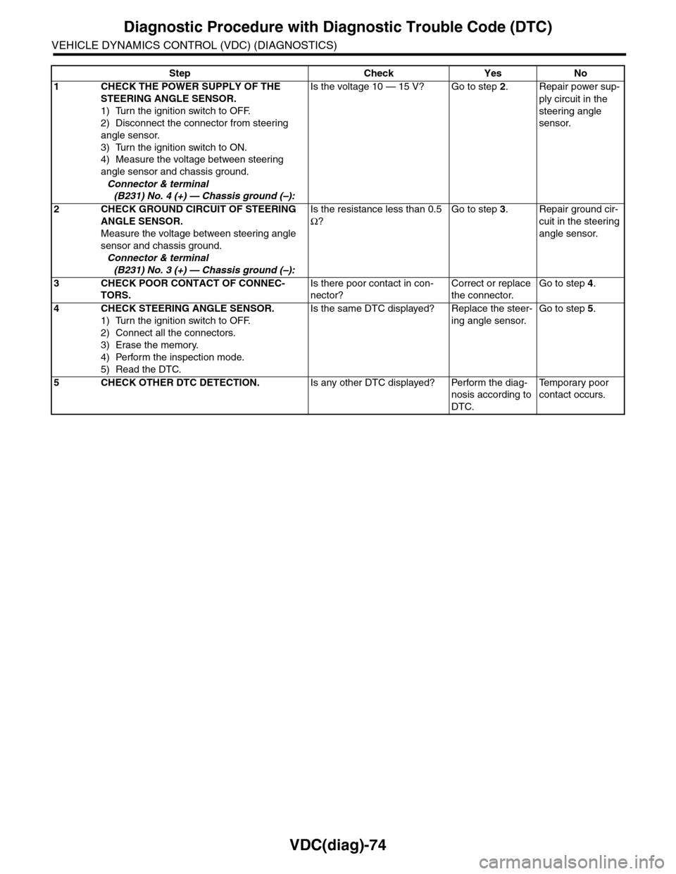
VDC(diag)-74
Diagnostic Procedure with Diagnostic Trouble Code (DTC)
VEHICLE DYNAMICS CONTROL (VDC) (DIAGNOSTICS)
Step Check Yes No
1CHECK THE POWER SUPPLY OF THE
STEERING ANGLE SENSOR.
1) Turn the ignition switch to OFF.
2) Disconnect the connector from steering
angle sensor.
3) Turn the ignition switch to ON.
4) Measure the voltage between steering
angle sensor and chassis ground.
Connector & terminal
(B231) No. 4 (+) — Chassis ground (–):
Is the voltage 10 — 15 V? Go to step 2.Repair power sup-
ply circuit in the
steering angle
sensor.
2CHECK GROUND CIRCUIT OF STEERING
ANGLE SENSOR.
Measure the voltage between steering angle
sensor and chassis ground.
Connector & terminal
(B231) No. 3 (+) — Chassis ground (–):
Is the resistance less than 0.5
Ω?
Go to step 3.Repair ground cir-
cuit in the steering
angle sensor.
3CHECK POOR CONTACT OF CONNEC-
TORS.
Is there poor contact in con-
nector?
Correct or replace
the connector.
Go to step 4.
4CHECK STEERING ANGLE SENSOR.
1) Turn the ignition switch to OFF.
2) Connect all the connectors.
3) Erase the memory.
4) Perform the inspection mode.
5) Read the DTC.
Is the same DTC displayed? Replace the steer-
ing angle sensor.
Go to step 5.
5CHECK OTHER DTC DETECTION.Is any other DTC displayed? Perform the diag-
nosis according to
DTC.
Te m p o r a r y p o o r
contact occurs.
Page 1068 of 2453
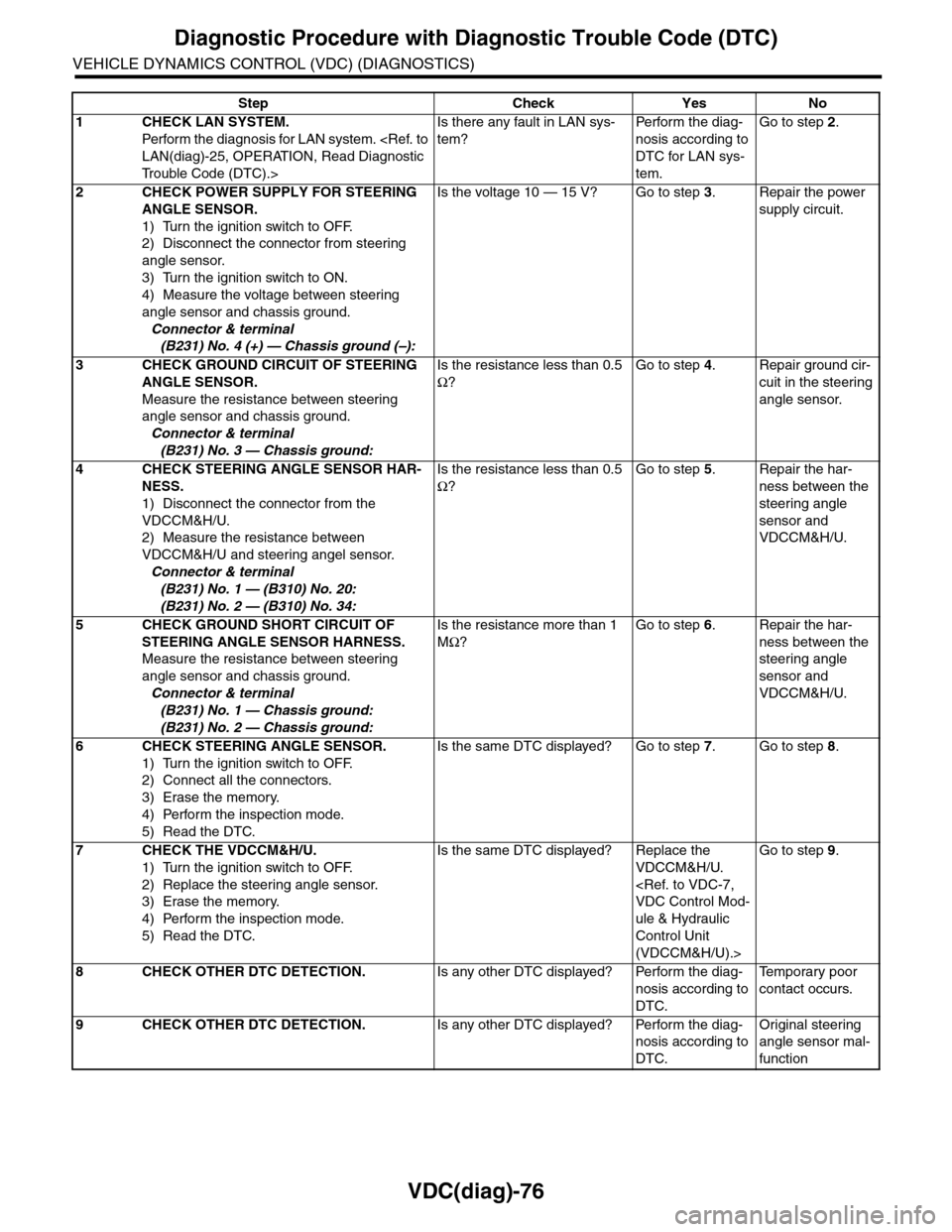
VDC(diag)-76
Diagnostic Procedure with Diagnostic Trouble Code (DTC)
VEHICLE DYNAMICS CONTROL (VDC) (DIAGNOSTICS)
Step Check Yes No
1CHECK LAN SYSTEM.
Perfor m the diagnosis for LAN system.
Tr o u b l e C o d e ( D T C ) . >
Is there any fault in LAN sys-
tem?
Pe r for m t h e d ia g -
nosis according to
DTC for LAN sys-
tem.
Go to step 2.
2CHECK POWER SUPPLY FOR STEERING
ANGLE SENSOR.
1) Turn the ignition switch to OFF.
2) Disconnect the connector from steering
angle sensor.
3) Turn the ignition switch to ON.
4) Measure the voltage between steering
angle sensor and chassis ground.
Connector & terminal
(B231) No. 4 (+) — Chassis ground (–):
Is the voltage 10 — 15 V? Go to step 3.Repair the power
supply circuit.
3CHECK GROUND CIRCUIT OF STEERING
ANGLE SENSOR.
Measure the resistance between steering
angle sensor and chassis ground.
Connector & terminal
(B231) No. 3 — Chassis ground:
Is the resistance less than 0.5
Ω?
Go to step 4.Repair ground cir-
cuit in the steering
angle sensor.
4CHECK STEERING ANGLE SENSOR HAR-
NESS.
1) Disconnect the connector from the
VDCCM&H/U.
2) Measure the resistance between
VDCCM&H/U and steering angel sensor.
Connector & terminal
(B231) No. 1 — (B310) No. 20:
(B231) No. 2 — (B310) No. 34:
Is the resistance less than 0.5
Ω?
Go to step 5.Repair the har-
ness between the
steering angle
sensor and
VDCCM&H/U.
5CHECK GROUND SHORT CIRCUIT OF
STEERING ANGLE SENSOR HARNESS.
Measure the resistance between steering
angle sensor and chassis ground.
Connector & terminal
(B231) No. 1 — Chassis ground:
(B231) No. 2 — Chassis ground:
Is the resistance more than 1
MΩ?
Go to step 6.Repair the har-
ness between the
steering angle
sensor and
VDCCM&H/U.
6CHECK STEERING ANGLE SENSOR.
1) Turn the ignition switch to OFF.
2) Connect all the connectors.
3) Erase the memory.
4) Perform the inspection mode.
5) Read the DTC.
Is the same DTC displayed? Go to step 7.Go to step 8.
7CHECK THE VDCCM&H/U.
1) Turn the ignition switch to OFF.
2) Replace the steering angle sensor.
3) Erase the memory.
4) Perform the inspection mode.
5) Read the DTC.
Is the same DTC displayed? Replace the
VDCCM&H/U.
ule & Hydraulic
Control Unit
(VDCCM&H/U).>
Go to step 9.
8CHECK OTHER DTC DETECTION.Is any other DTC displayed? Perform the diag-
nosis according to
DTC.
Te m p o r a r y p o o r
contact occurs.
9CHECK OTHER DTC DETECTION.Is any other DTC displayed? Perform the diag-
nosis according to
DTC.
Original steering
angle sensor mal-
function