2009 SUBARU TRIBECA er ss displayed
[x] Cancel search: er ss displayedPage 1195 of 2453
EN(H6DO)(diag)-34
Read Diagnostic Trouble Code (DTC)
ENGINE (DIAGNOSTICS)
10.Read Diagnostic Trouble
Code (DTC)
A: OPERATION
1. SUBARU SELECT MONITOR (NORMAL
MODE)
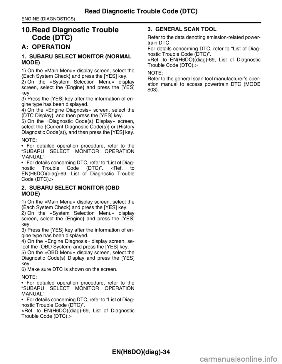
1) On the «Main Menu» display screen, select the
{Each System Check} and press the [YES] key.
2) On the «System Selection Menu» display
screen, select the {Engine} and press the [YES]
key.
3) Press the [YES] key after the information of en-
gine type has been displayed.
4) On the «Engine Diagnosis» screen, select the
{DTC Display}, and then press the [YES] key.
5) On the «Diagnostic Code(s) Display» screen,
select the {Current Diagnostic Code(s)} or {History
Diagnostic Code(s)}, and then press the [YES] key.
NOTE:
•For detailed operation procedure, refer to the
“SUBARU SELECT MONITOR OPERATION
MANUAL”.
•For details concerning DTC, refer to “List of Diag-
nostic Trouble Code (DTC)”.
Code (DTC).>
2. SUBARU SELECT MONITOR (OBD
MODE)
1) On the «Main Menu» display screen, select the
{Each System Check} and press the [YES] key.
2) On the «System Selection Menu» display
screen, select the {Engine} and press the [YES]
key.
3) Press the [YES] key after the information of en-
gine type has been displayed.
4) On the «Engine Diagnosis» display screen, se-
lect the {OBD System} and press the [YES] key.
5) On the «OBD Menu» display screen, select the
Diagnostic Code(s) Display and press the [YES]
key.
6) Make sure DTC is shown on the screen.
NOTE:
•For detailed operation procedure, refer to the
“SUBARU SELECT MONITOR OPERATION
MANUAL”.
•For details concerning DTC, refer to “List of Diag-
nostic Trouble Code (DTC)”.
3. GENERAL SCAN TOOL
Refer to the data denoting emission-related power-
train DTC.
For details concerning DTC, refer to “List of Diag-
nostic Trouble Code (DTC)”.
NOTE:
Refer to the general scan tool manufacturer’s oper-
ation manual to access powertrain DTC (MODE
$03).
Page 1199 of 2453
EN(H6DO)(diag)-38
Inspection Mode
ENGINE (DIAGNOSTICS)
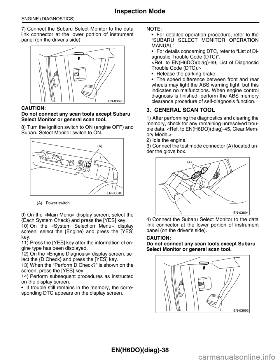
7) Connect the Subaru Select Monitor to the data
link connector at the lower portion of instrument
panel (on the driver's side).
CAUTION:
Do not connect any scan tools except Subaru
Select Monitor or general scan tool.
8) Turn the ignition switch to ON (engine OFF) and
Subaru Select Monitor switch to ON.
9) On the «Main Menu» display screen, select the
{Each System Check} and press the [YES] key.
10) On the «System Selection Menu» display
screen, select the {Engine} and press the [YES]
key.
11) Press the [YES] key after the information of en-
gine type has been displayed.
12) On the «Engine Diagnosis» display screen, se-
lect the {D Check} and press the [YES] key.
13) When the “Perform D Check?” is shown on the
screen, press the [YES] key.
14) Perform subsequent procedures as instructed
on the display screen.
•If trouble still remains in the memory, the corre-
sponding DTC appears on the display screen.
NOTE:
•For detailed operation procedure, refer to the
“SUBARU SELECT MONITOR OPERATION
MANUAL”.
•For details concerning DTC, refer to “List of Di-
agnostic Trouble Code (DTC)”.
•Release the parking brake.
•The speed difference between front and rear
wheels may light the ABS warning light, but this
indicates no malfunctions. When engine control
diagnosis is finished, perform the ABS memory
clearance procedure of self-diagnosis function.
3. GENERAL SCAN TOOL
1) After performing the diagnostics and clearing the
memory, check for any remaining unresolved trou-
ble data.
2) Idle the engine.
3) Connect the test mode connector (A) located un-
der the glove box.
4) Connect the Subaru Select Monitor to the data
link connector at the lower portion of instrument
panel (on the driver’s side).
CAUTION:
Do not connect any scan tools except Subaru
Select Monitor or general scan tool.
(A) Power switch
EN-03693
(A)
EN-00040
EN-03694
(4)
EN-03693
Page 1206 of 2453
EN(H6DO)(diag)-45
Clear Memory Mode
ENGINE (DIAGNOSTICS)
13.Clear Memory Mode
A: OPERATION
1. SUBARU SELECT MONITOR (NORMAL
MODE)
1) On the «Main Menu» display screen, select the
{Each System Check} and press the [YES] key.
2) On the «System Selection Menu» display
screen, select the {Engine} and press the [YES]
key.
3) Press the [YES] key after the information of en-
gine type has been displayed.
4) On the «Engine Diagnosis» display screen, se-
lect the {Memory Clear} and press the [YES] key.
5) When the “Done” and “Turn Ignition Switch OFF”
are shown on the display screen, turn the ignition
switch to OFF and then Subaru Select Monitor
switch to OFF.
NOTE:
•Initial diagnosis of electronic throttle control is
performed after memory clearance. For this rea-
son, start the engine after 10 seconds or more have
elapsed since the ignition switch was turned to ON.
•For detailed operation procedure, refer to the
“SUBARU SELECT MONITOR OPERATION
MANUAL”.
2. SUBARU SELECT MONITOR (OBD
MODE)
1) On the «Main Menu» display screen, select the
{Each System Check} and press the [YES] key.
2) On the «System Selection Menu» display
screen, select the {Engine} and press the [YES]
key.
3) Press the [YES] key after the information of en-
gine type has been displayed.
4) On the «Engine Diagnosis» display screen, se-
lect the {OBD System} and press the [YES] key.
5) On the «OBD Menu» display screen, select
{DTC Clear} and press the [YES] key.
6) When the “Perform Diagnostic Code(s) Clear?”
is shown on the screen, press the [YES] key.
7) Turn the ignition switch to OFF and then turn the
Subaru Select Monitor switch to OFF.
NOTE:
•Initial diagnosis of electronic throttle control is
performed after memory clearance. For this rea-
son, start the engine after 10 seconds or more have
elapsed since the ignition switch was turned to ON.
•For detailed operation procedure, refer to the
“SUBARU SELECT MONITOR OPERATION
MANUAL”.
3. GENERAL SCAN TOOL
For procedures clearing memory using the general
scan tool, refer to the general scan tool operation
manual.
Page 1207 of 2453
EN(H6DO)(diag)-46
Compulsory Valve Operation Check Mode
ENGINE (DIAGNOSTICS)
14.Compulsory Valve Operation
Check Mode
A: OPERATION
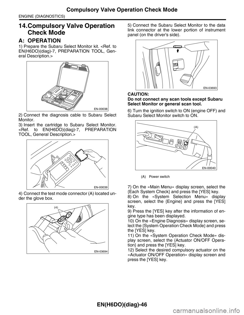
1) Prepare the Subaru Select Monitor kit.
eral Description.>
2) Connect the diagnosis cable to Subaru Select
Monitor.
3) Insert the cartridge to Subaru Select Monitor.
4) Connect the test mode connector (A) located un-
der the glove box.
5) Connect the Subaru Select Monitor to the data
link connector at the lower portion of instrument
panel (on the driver's side).
CAUTION:
Do not connect any scan tools except Subaru
Select Monitor or general scan tool.
6) Turn the ignition switch to ON (engine OFF) and
Subaru Select Monitor switch to ON.
7) On the «Main Menu» display screen, select the
{Each System Check} and press the [YES] key.
8) On the «System Selection Menu» display
screen, select the {Engine} and press the [YES]
key.
9) Press the [YES] key after the information of en-
gine type has been displayed.
10) On the «Engine Diagnosis» display screen, se-
lect the {System Operation Check Mode} and press
the [YES] key.
11) On the «System Operation Check Mode» dis-
play screen, select the {Actuator ON/OFF Opera-
tion} and press the [YES] key.
12) Select the desired compulsory actuator on the
«Actuator ON/OFF Operation» display screen and
press the [YES] key.
EN-00038
EN-00039
EN-03694
(4)
(A) Power switch
EN-03693
(A)
EN-00040
Page 1208 of 2453
![SUBARU TRIBECA 2009 1.G Service Workshop Manual EN(H6DO)(diag)-47
Compulsory Valve Operation Check Mode
ENGINE (DIAGNOSTICS)
13) Pressing the [NO] key completes the compul-
sory valve operation check mode. The display will
then return to SUBARU TRIBECA 2009 1.G Service Workshop Manual EN(H6DO)(diag)-47
Compulsory Valve Operation Check Mode
ENGINE (DIAGNOSTICS)
13) Pressing the [NO] key completes the compul-
sory valve operation check mode. The display will
then return to](/manual-img/17/7322/w960_7322-1207.png)
EN(H6DO)(diag)-47
Compulsory Valve Operation Check Mode
ENGINE (DIAGNOSTICS)
13) Pressing the [NO] key completes the compul-
sory valve operation check mode. The display will
then return to the «Actuator ON/OFF Operation»
screen.
•A list of the support data is shown in the following
table.
NOTE:
•The following parts will be displayed but not
functional.
•For detailed operation procedure, refer to the
“SUBARU SELECT MONITOR OPERATION
MANUAL”.
Description Display
Compulsory fuel pump relay oper-
ation checkFuel Pump
Compulsory radiator fan relay
operation checkRadiator Fan Relay
Compulsory air conditioning relay
operation checkA/C Compressor Relay
Compulsory purge control sole-
noid valve operation checkCPC Solenoid
Compulsory drain valve operation
checkVe n t C o n t r o l S o l e n o i d
Display
EGR Solenoid
ASV Solenoid
FICD Solenoid
Pressure Switching Solenoid 1
Pressure Switching Solenoid 2
Wa st e g at e Con t r ol S ol e no i d
AAI Solenoid
Exhaust Bypass Valve Control Permit Flag
PCV Solenoid
Fuel tank sensor control valve
Page 1220 of 2453
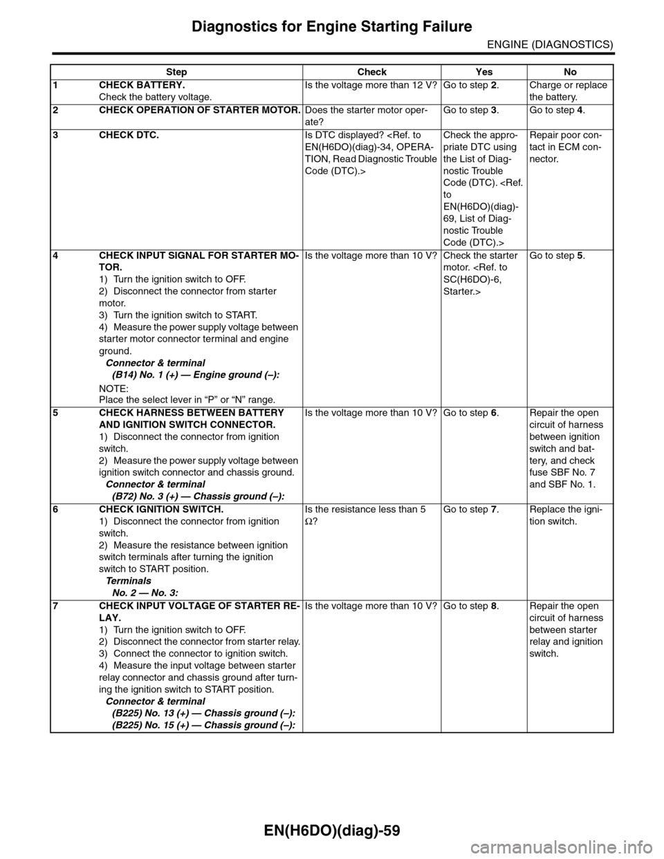
EN(H6DO)(diag)-59
Diagnostics for Engine Starting Failure
ENGINE (DIAGNOSTICS)
Step Check Yes No
1CHECK BATTERY.
Check the battery voltage.
Is the voltage more than 12 V? Go to step 2.Charge or replace
the battery.
2CHECK OPERATION OF STARTER MOTOR.Does the starter motor oper-
ate?
Go to step 3.Go to step 4.
3CHECK DTC.Is DTC displayed?
TION, Read Diagnostic Trouble
Code (DTC).>
Check the appro-
priate DTC using
the List of Diag-
nostic Trouble
Code (DTC).
EN(H6DO)(diag)-
69, List of Diag-
nostic Trouble
Code (DTC).>
Repair poor con-
tact in ECM con-
nector.
4CHECK INPUT SIGNAL FOR STARTER MO-
TOR.
1) Turn the ignition switch to OFF.
2) Disconnect the connector from starter
motor.
3) Turn the ignition switch to START.
4) Measure the power supply voltage between
starter motor connector terminal and engine
ground.
Connector & terminal
(B14) No. 1 (+) — Engine ground (–):
NOTE:Place the select lever in “P” or “N” range.
Is the voltage more than 10 V? Check the starter
motor.
Starter.>
Go to step 5.
5CHECK HARNESS BETWEEN BATTERY
AND IGNITION SWITCH CONNECTOR.
1) Disconnect the connector from ignition
switch.
2) Measure the power supply voltage between
ignition switch connector and chassis ground.
Connector & terminal
(B72) No. 3 (+) — Chassis ground (–):
Is the voltage more than 10 V? Go to step 6.Repair the open
circuit of harness
between ignition
switch and bat-
tery, and check
fuse SBF No. 7
and SBF No. 1.
6CHECK IGNITION SWITCH.
1) Disconnect the connector from ignition
switch.
2) Measure the resistance between ignition
switch terminals after turning the ignition
switch to START position.
Te r m i n a l s
No. 2 — No. 3:
Is the resistance less than 5
Ω?
Go to step 7.Replace the igni-
tion switch.
7CHECK INPUT VOLTAGE OF STARTER RE-
LAY.
1) Turn the ignition switch to OFF.
2) Disconnect the connector from starter relay.
3) Connect the connector to ignition switch.
4) Measure the input voltage between starter
relay connector and chassis ground after turn-
ing the ignition switch to START position.
Connector & terminal
(B225) No. 13 (+) — Chassis ground (–):
(B225) No. 15 (+) — Chassis ground (–):
Is the voltage more than 10 V? Go to step 8.Repair the open
circuit of harness
between starter
relay and ignition
switch.
Page 1238 of 2453
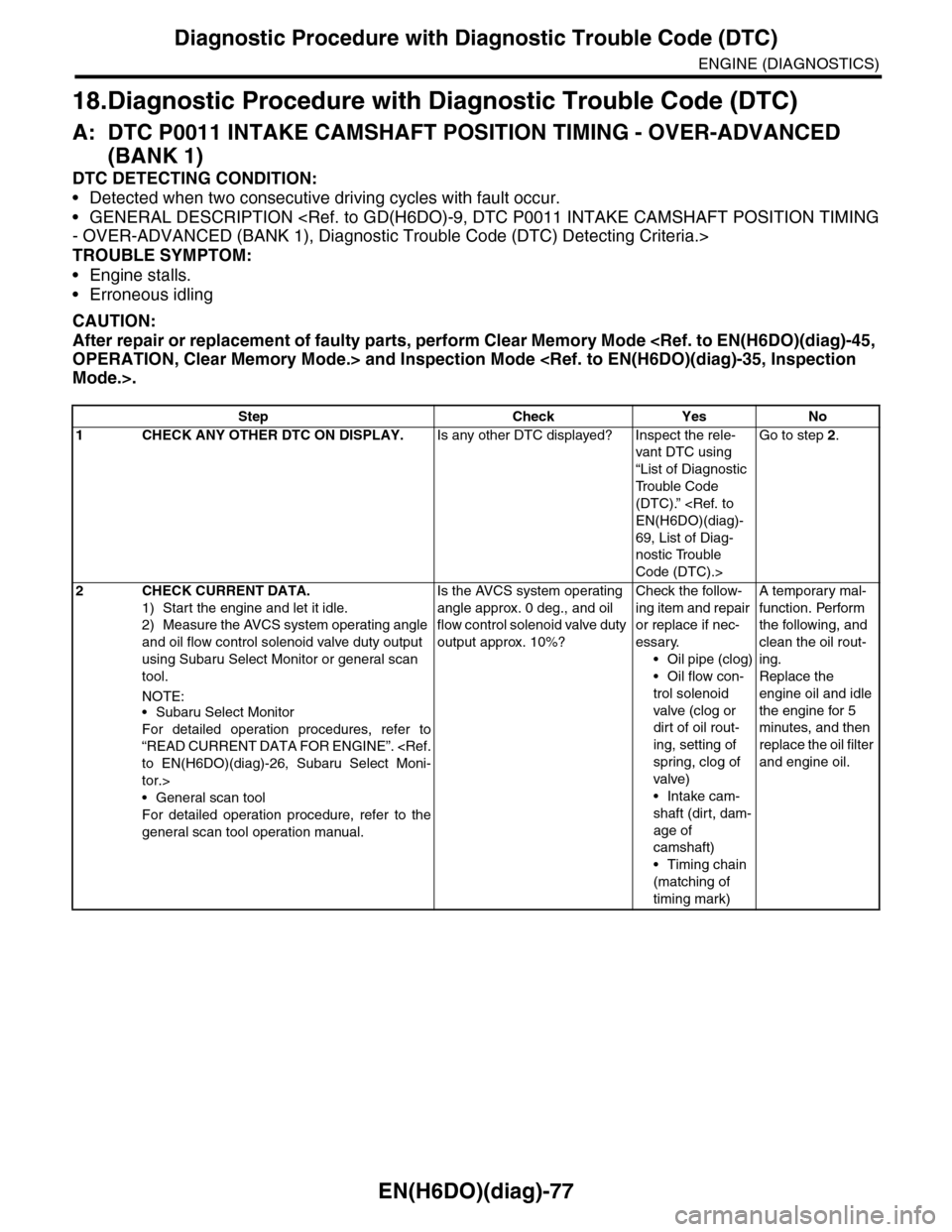
EN(H6DO)(diag)-77
Diagnostic Procedure with Diagnostic Trouble Code (DTC)
ENGINE (DIAGNOSTICS)
18.Diagnostic Procedure with Diagnostic Trouble Code (DTC)
A: DTC P0011 INTAKE CAMSHAFT POSITION TIMING - OVER-ADVANCED
(BANK 1)
DTC DETECTING CONDITION:
•Detected when two consecutive driving cycles with fault occur.
•GENERAL DESCRIPTION
TROUBLE SYMPTOM:
•Engine stalls.
•Erroneous idling
CAUTION:
After repair or replacement of faulty parts, perform Clear Memory Mode
Step Check Yes No
1CHECK ANY OTHER DTC ON DISPLAY.Is any other DTC displayed? Inspect the rele-
vant DTC using
“List of Diagnostic
Tr o u b l e C o d e
(DTC).”
69, List of Diag-
nostic Trouble
Code (DTC).>
Go to step 2.
2CHECK CURRENT DATA.
1) Start the engine and let it idle.
2) Measure the AVCS system operating angle
and oil flow control solenoid valve duty output
using Subaru Select Monitor or general scan
tool.
NOTE:•Subaru Select Monitor
For detailed operation procedures, refer to
“READ CURRENT DATA FOR ENGINE”.
tor.>
•General scan tool
For detailed operation procedure, refer to the
general scan tool operation manual.
Is the AVCS system operating
angle approx. 0 deg., and oil
flow control solenoid valve duty
output approx. 10%?
Check the follow-
ing item and repair
or replace if nec-
essary.
•Oil pipe (clog)
•Oil flow con-
trol solenoid
valve (clog or
dirt of oil rout-
ing, setting of
spring, clog of
valve)
•Intake cam-
shaft (dirt, dam-
age of
camshaft)
•Timing chain
(matching of
timing mark)
A temporary mal-
function. Perform
the following, and
clean the oil rout-
ing.
Replace the
engine oil and idle
the engine for 5
minutes, and then
replace the oil filter
and engine oil.
Page 1239 of 2453
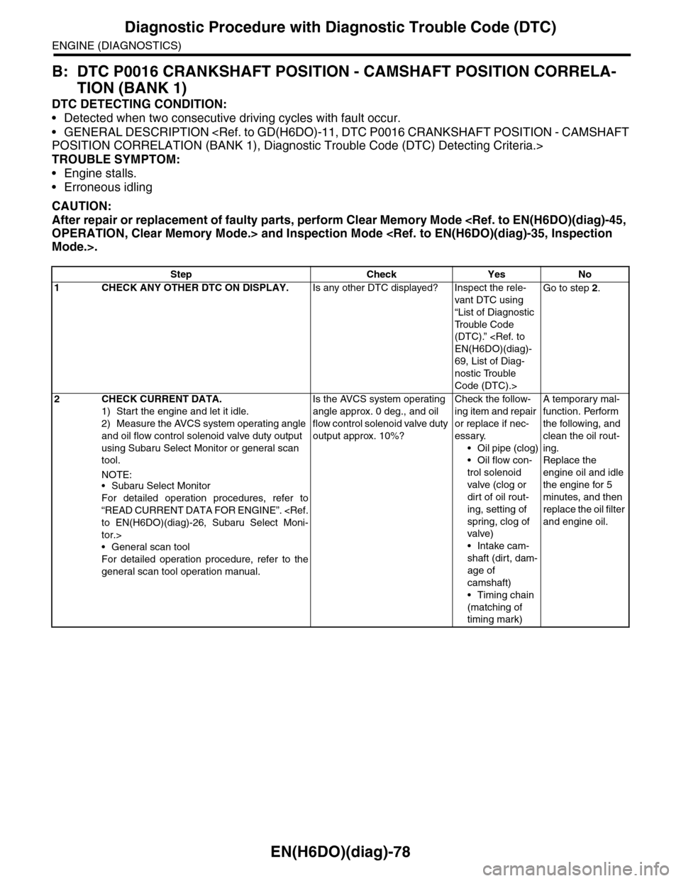
EN(H6DO)(diag)-78
Diagnostic Procedure with Diagnostic Trouble Code (DTC)
ENGINE (DIAGNOSTICS)
B: DTC P0016 CRANKSHAFT POSITION - CAMSHAFT POSITION CORRELA-
TION (BANK 1)
DTC DETECTING CONDITION:
•Detected when two consecutive driving cycles with fault occur.
•GENERAL DESCRIPTION
TROUBLE SYMPTOM:
•Engine stalls.
•Erroneous idling
CAUTION:
After repair or replacement of faulty parts, perform Clear Memory Mode
Step Check Yes No
1CHECK ANY OTHER DTC ON DISPLAY.Is any other DTC displayed? Inspect the rele-
vant DTC using
“List of Diagnostic
Tr o u b l e C o d e
(DTC).”
69, List of Diag-
nostic Trouble
Code (DTC).>
Go to step 2.
2CHECK CURRENT DATA.
1) Start the engine and let it idle.
2) Measure the AVCS system operating angle
and oil flow control solenoid valve duty output
using Subaru Select Monitor or general scan
tool.
NOTE:•Subaru Select Monitor
For detailed operation procedures, refer to
“READ CURRENT DATA FOR ENGINE”.
tor.>
•General scan tool
For detailed operation procedure, refer to the
general scan tool operation manual.
Is the AVCS system operating
angle approx. 0 deg., and oil
flow control solenoid valve duty
output approx. 10%?
Check the follow-
ing item and repair
or replace if nec-
essary.
•Oil pipe (clog)
•Oil flow con-
trol solenoid
valve (clog or
dirt of oil rout-
ing, setting of
spring, clog of
valve)
•Intake cam-
shaft (dirt, dam-
age of
camshaft)
•Timing chain
(matching of
timing mark)
A temporary mal-
function. Perform
the following, and
clean the oil rout-
ing.
Replace the
engine oil and idle
the engine for 5
minutes, and then
replace the oil filter
and engine oil.