2009 SUBARU TRIBECA transmission oil
[x] Cancel search: transmission oilPage 1089 of 2453
VDC-8
VDC Control Module & Hydraulic Control Unit (VDCCM&H/U)
VEHICLE DYNAMICS CONTROL (VDC)
4) Connect the VDCCM&H/U connectors.
NOTE:
•Be sure to remove all foreign matter from inside
the connector before connecting.
•Make sure the VDCCM&H/U connector is se-
curely locked.
5) Bleed air from the brake system.
C: INSPECTION
1) Check the condition of connection and settle-
ment of connector.
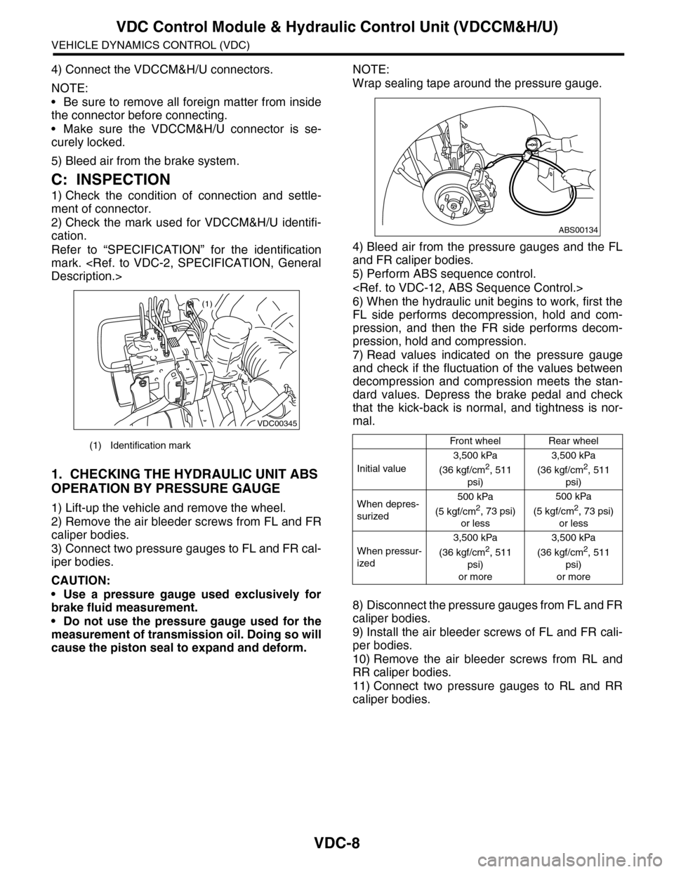
2) Check the mark used for VDCCM&H/U identifi-
cation.
Refer to “SPECIFICATION” for the identification
mark.
1. CHECKING THE HYDRAULIC UNIT ABS
OPERATION BY PRESSURE GAUGE
1) Lift-up the vehicle and remove the wheel.
2) Remove the air bleeder screws from FL and FR
caliper bodies.
3) Connect two pressure gauges to FL and FR cal-
iper bodies.
CAUTION:
•Use a pressure gauge used exclusively for
brake fluid measurement.
•Do not use the pressure gauge used for the
measurement of transmission oil. Doing so will
cause the piston seal to expand and deform.
NOTE:
Wrap sealing tape around the pressure gauge.
4) Bleed air from the pressure gauges and the FL
and FR caliper bodies.
5) Perform ABS sequence control.
6) When the hydraulic unit begins to work, first the
FL side performs decompression, hold and com-
pression, and then the FR side performs decom-
pression, hold and compression.
7) Read values indicated on the pressure gauge
and check if the fluctuation of the values between
decompression and compression meets the stan-
dard values. Depress the brake pedal and check
that the kick-back is normal, and tightness is nor-
mal.
8) Disconnect the pressure gauges from FL and FR
caliper bodies.
9) Install the air bleeder screws of FL and FR cali-
per bodies.
10) Remove the air bleeder screws from RL and
RR caliper bodies.
11) Connect two pressure gauges to RL and RR
caliper bodies.
(1) Identification mark
VDC00345
(1)
Front wheelRear wheel
Initial value
3,500 kPa
(36 kgf/cm2, 511
psi)
3,500 kPa
(36 kgf/cm2, 511
psi)
When depres-
surized
500 kPa
(5 kgf/cm2, 73 psi)
or less
500 kPa
(5 kgf/cm2, 73 psi)
or less
When pressur-
ized
3,500 kPa
(36 kgf/cm2, 511
psi)
or more
3,500 kPa
(36 kgf/cm2, 511
psi)
or more
ABS00134
Page 1090 of 2453
VDC-9
VDC Control Module & Hydraulic Control Unit (VDCCM&H/U)
VEHICLE DYNAMICS CONTROL (VDC)
12) Bleed air from the brake system.
13) Bleed air from RL and RR caliper bodies, and
pressure gauge.
14) Perform ABS sequence control.
15) When the hydraulic unit begins to work, first the
RR side performs decompression, hold and com-
pression, and then the RL side performs decom-
pression, hold and compression.
16) Read values indicated on the pressure gauge
and check if the fluctuation of the values between
decompression and compression meets specifica-
tion. Depress the brake pedal and check that the
kick-back is normal, and tightness is normal.
17) Disconnect the pressure gauge from the RL
and RR caliper bodies.
18) Install the air bleeder screws of RL and RR cal-
iper bodies.
19) Bleed air from the brake system.
2. CHECKING THE HYDRAULIC UNIT ABS
OPERATION WITH THE BRAKE TESTER
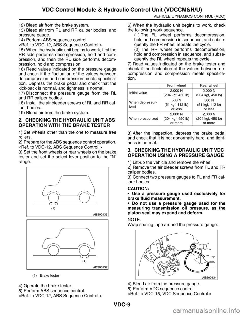
1) Set wheels other than the one to measure free
rollers.
2) Prepare for the ABS sequence control operation.
3) Set the front wheels or rear wheels on the brake
tester and set the select lever position to the “N”
range.
4) Operate the brake tester.
5) Perform ABS sequence control.
6) When the hydraulic unit begins to work, check
the following work sequence.
(1) The FL wheel performs decompression,
hold and compression in sequence, and subse-
quently the FR wheel repeats the cycle.
(2) The RR wheel performs decompression,
hold and compression in sequence, and subse-
quently the RL wheel repeats the cycle.
7) Read values indicated on the brake tester and
check if the fluctuation of the values between de-
compression and compression meets specifica-
tion.
8) After the inspection, depress the brake pedal
and check that it is not abnormally hard, and tight-
ness is normal.
3. CHECKING THE HYDRAULIC UNIT VDC
OPERATION USING A PRESSURE GAUGE
1) Lift-up the vehicle and remove the wheel.
2) Remove the air bleeder screws from FL and FR
caliper bodies.
3) Connect two pressure gauges to FL and FR cal-
iper bodies.
CAUTION:
•Use a pressure gauge used exclusively for
brake fluid measurement.
•Do not use a pressure gauge used for the
measuring transmission oil pressure, as the
piston seal may expand and deform.
NOTE:
Wrap sealing tape around the pressure gauge.
4) Bleed air from the pressure gauge.
5) Perform VDC sequence control.
(1) Brake tester
ABS00136
(1)
ABS00137
(1)
Front wheelRear wheel
Initial value2,000 N
(204 kgf, 450 lb)
2,000 N
(204 kgf, 450 lb)
When depressur-
ized
500 N
(51 kgf, 112 lb)
or less
500 N
(51 kgf, 112 lb)
or less
When pressurized
2,000 N
(204 kgf, 450 lb)
or more
2,000 N
(204 kgf, 450 lb)
or more
ABS00134
Page 1149 of 2453
CO(H6DO)-30
Engine Cooling System Trouble in General
COOLING
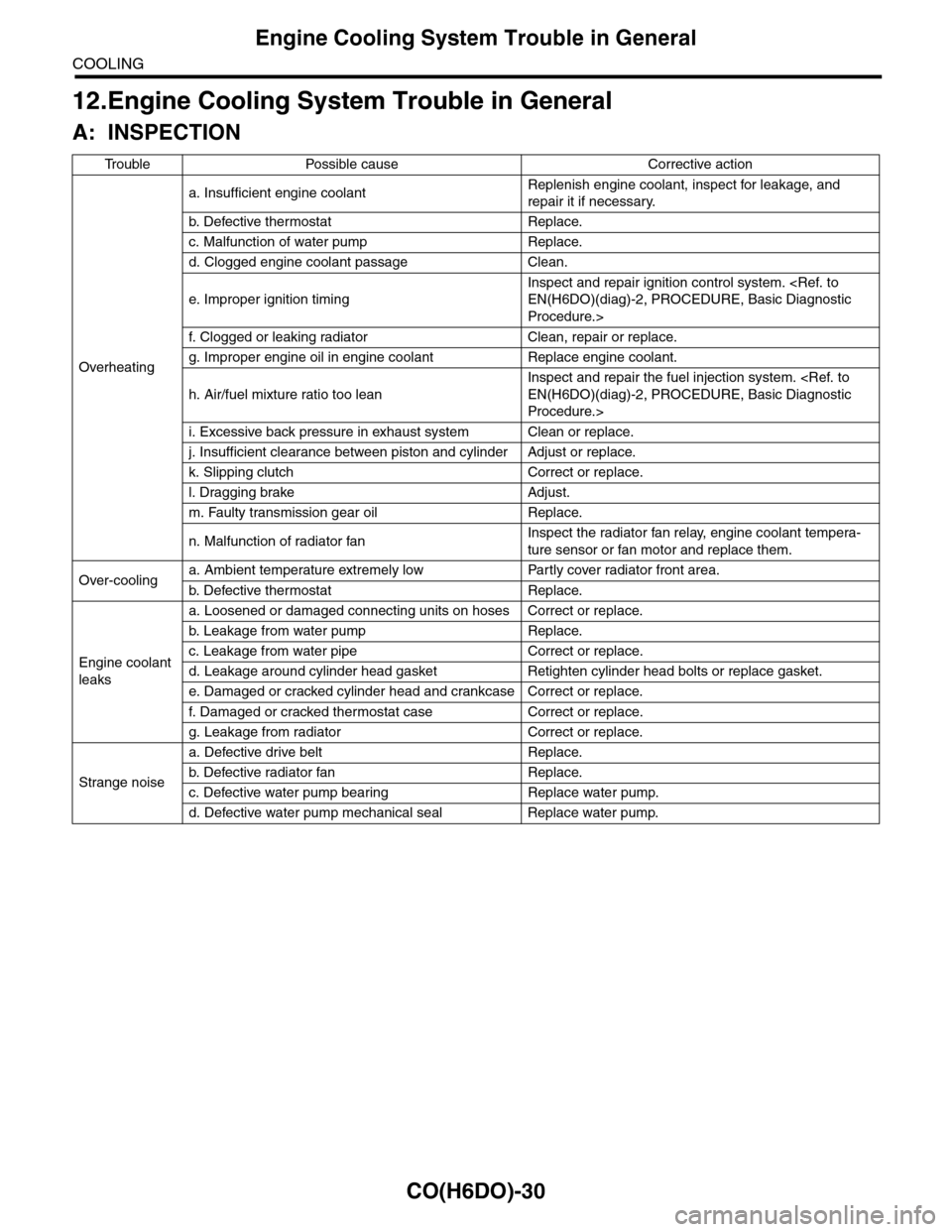
12.Engine Cooling System Trouble in General
A: INSPECTION
Tr o u b l e P o s s i b l e c a u s e C o r r e c t i v e a c t i o n
Overheating
a. Insufficient engine coolantReplenish engine coolant, inspect for leakage, and
repair it if necessary.
b. De fe c ti ve t he r mo st a t Rep la c e.
c. Malfunction of water pump Replace.
d. Clogged engine coolant passage Clean.
e. Improper ignition timing
Inspect and repair ignition control system.
Procedure.>
f. Clogged or leaking radiator Clean, repair or replace.
g. Improper engine oil in engine coolant Replace engine coolant.
h. Air/fuel mixture ratio too lean
Inspect and repair the fuel injection system.
Procedure.>
i. Excessive back pressure in exhaust system Clean or replace.
j. Insufficient clearance between piston and cylinder Adjust or replace.
k. Slipping clutch Correct or replace.
l. Dragging brake Adjust.
m. Faulty transmission gear oil Replace.
n. Malfunction of radiator fanInspect the radiator fan relay, engine coolant tempera-
ture sensor or fan motor and replace them.
Over-coolinga. Ambient temperature extremely low Partly cover radiator front area.
b. De fe c ti ve t he r mo st a t Rep la c e.
Engine coolant
leaks
a. Loosened or damaged connecting units on hoses Correct or replace.
b. L ea k ag e f r o m wat e r pu mp Rep la c e.
c. Leakage from water pipe Correct or replace.
d. Leakage around cylinder head gasket Retighten cylinder head bolts or replace gasket.
e. Damaged or cracked cylinder head and crankcase Correct or replace.
f. Damaged or cracked ther mostat case Correct or replace.
g. Leakage from radiator Correct or replace.
Strange noise
a. Defective drive belt Replace.
b. De fe c ti ve ra di a t or fan Rep la c e.
c. Defective water pump bearing Replace water pump.
d. Defective water pump mechanical seal Replace water pump.
Page 1880 of 2453
ME(H6DO)-14
General Description
MECHANICAL
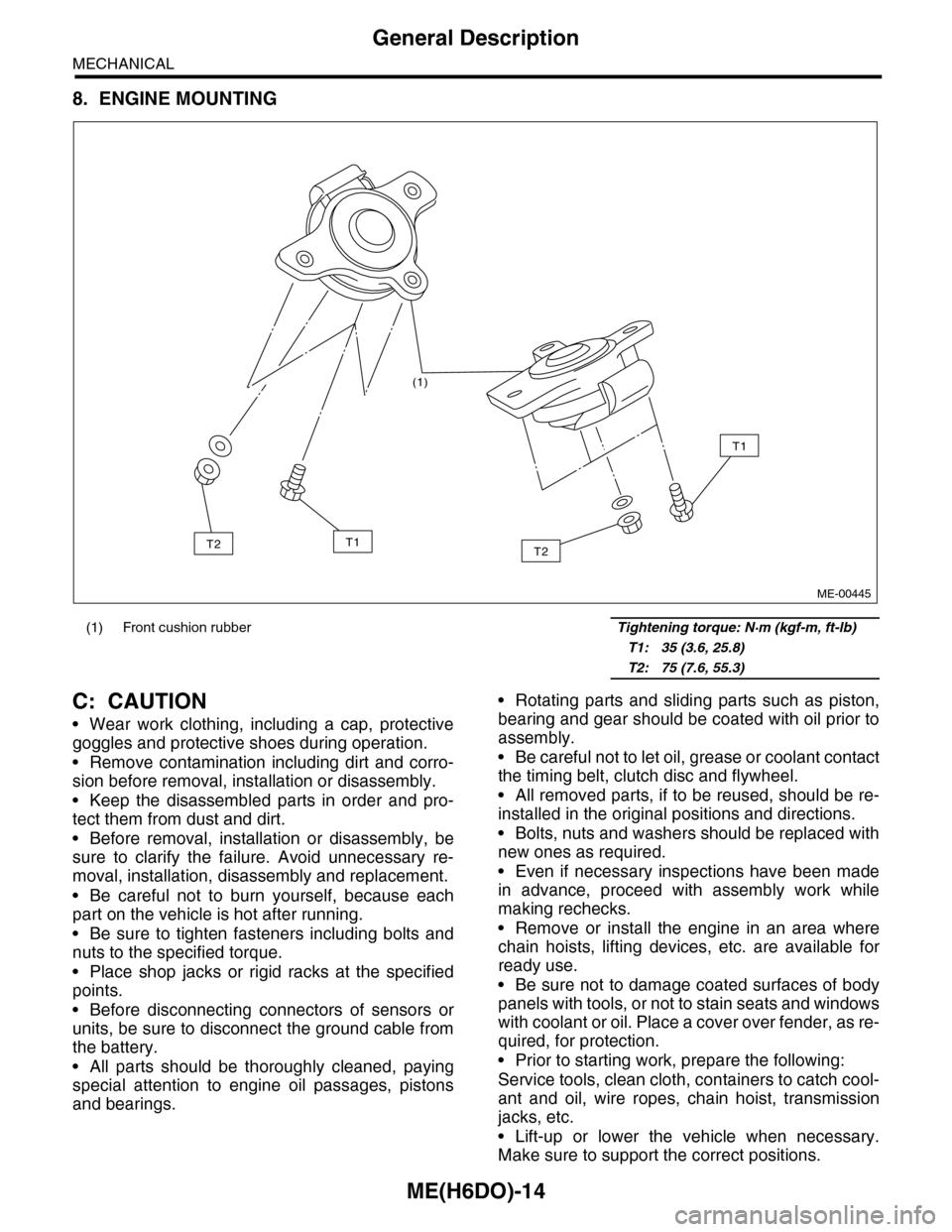
8. ENGINE MOUNTING
C: CAUTION
•Wear work clothing, including a cap, protective
goggles and protective shoes during operation.
•Remove contamination including dirt and corro-
sion before removal, installation or disassembly.
•Keep the disassembled parts in order and pro-
tect them from dust and dirt.
•Before removal, installation or disassembly, be
sure to clarify the failure. Avoid unnecessary re-
moval, installation, disassembly and replacement.
•Be careful not to burn yourself, because each
part on the vehicle is hot after running.
•Be sure to tighten fasteners including bolts and
nuts to the specified torque.
•Place shop jacks or rigid racks at the specified
points.
•Before disconnecting connectors of sensors or
units, be sure to disconnect the ground cable from
the battery.
•All parts should be thoroughly cleaned, paying
special attention to engine oil passages, pistons
and bearings.
•Rotating parts and sliding parts such as piston,
bearing and gear should be coated with oil prior to
assembly.
•Be careful not to let oil, grease or coolant contact
the timing belt, clutch disc and flywheel.
•All removed parts, if to be reused, should be re-
installed in the original positions and directions.
•Bolts, nuts and washers should be replaced with
new ones as required.
•Even if necessary inspections have been made
in advance, proceed with assembly work while
making rechecks.
•Remove or install the engine in an area where
chain hoists, lifting devices, etc. are available for
ready use.
•Be sure not to damage coated surfaces of body
panels with tools, or not to stain seats and windows
with coolant or oil. Place a cover over fender, as re-
quired, for protection.
•Prior to starting work, prepare the following:
Service tools, clean cloth, containers to catch cool-
ant and oil, wire ropes, chain hoist, transmission
jacks, etc.
•Lift-up or lower the vehicle when necessary.
Make sure to support the correct positions.
(1) Front cushion rubber Tightening torque: N·m (kgf-m, ft-lb)
T1: 35 (3.6, 25.8)
T2: 75 (7.6, 55.3)
(1)
T2
T1
T1T2
ME-00445
Page 1901 of 2453
ME(H6DO)-35
Engine Assembly
MECHANICAL
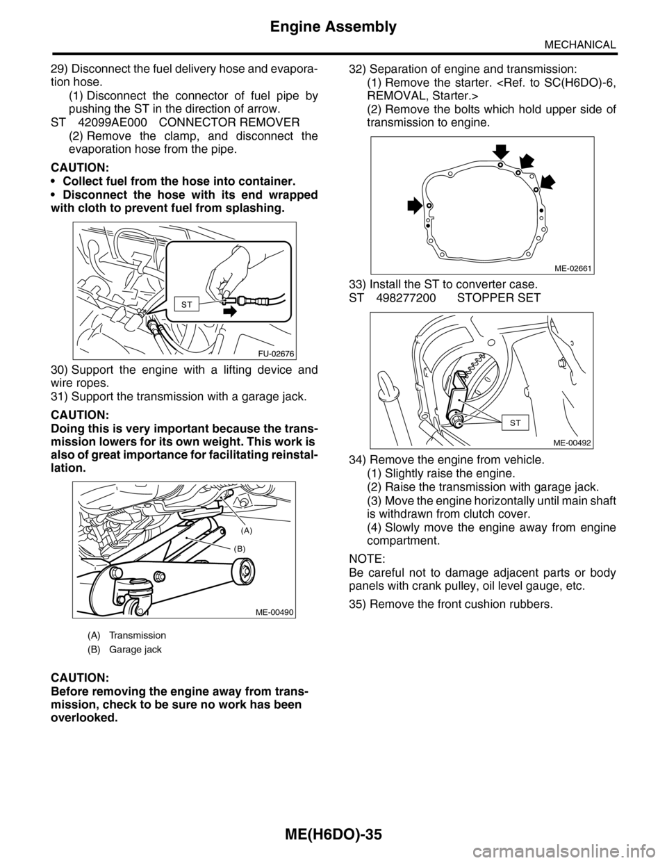
29) Disconnect the fuel delivery hose and evapora-
tion hose.
(1) Disconnect the connector of fuel pipe by
pushing the ST in the direction of arrow.
ST 42099AE000 CONNECTOR REMOVER
(2) Remove the clamp, and disconnect the
evaporation hose from the pipe.
CAUTION:
•Collect fuel from the hose into container.
•Disconnect the hose with its end wrapped
with cloth to prevent fuel from splashing.
30) Support the engine with a lifting device and
wire ropes.
31) Support the transmission with a garage jack.
CAUTION:
Doing this is very important because the trans-
mission lowers for its own weight. This work is
also of great importance for facilitating reinstal-
lation.
CAUTION:
Before removing the engine away from trans-
mission, check to be sure no work has been
overlooked.
32) Separation of engine and transmission:
(1) Remove the starter.
(2) Remove the bolts which hold upper side of
transmission to engine.
33) Install the ST to converter case.
ST 498277200 STOPPER SET
34) Remove the engine from vehicle.
(1) Slightly raise the engine.
(2) Raise the transmission with garage jack.
(3) Move the engine horizontally until main shaft
is withdrawn from clutch cover.
(4) Slowly move the engine away from engine
compartment.
NOTE:
Be careful not to damage adjacent parts or body
panels with crank pulley, oil level gauge, etc.
35) Remove the front cushion rubbers.
(A) Transmission
(B) Garage jack
(A)
(B)
ME-00490
ME-02661
ST
ME-00492
Page 1902 of 2453
ME(H6DO)-36
Engine Assembly
MECHANICAL
B: INSTALLATION
1) Install the front cushion rubbers.
Tightening torque:
35 N·m (3.6 kgf-m, 25.8 ft-lb)
2) Position the engine in engine compartment and
align it with transmission.
NOTE:
Be careful not to damage adjacent parts or body
panels with crank pulley, oil level gauge, etc.
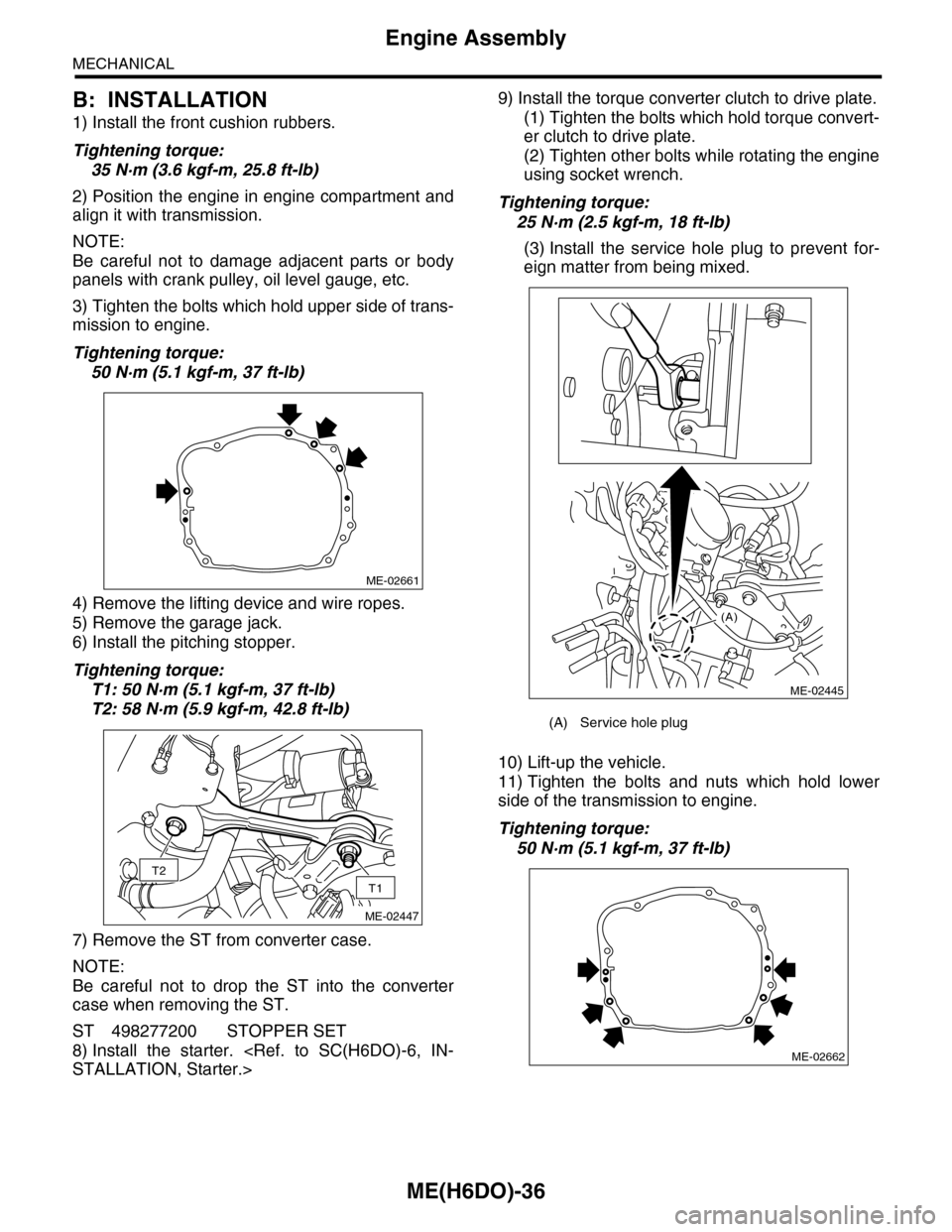
3) Tighten the bolts which hold upper side of trans-
mission to engine.
Tightening torque:
50 N·m (5.1 kgf-m, 37 ft-lb)
4) Remove the lifting device and wire ropes.
5) Remove the garage jack.
6) Install the pitching stopper.
Tightening torque:
T1: 50 N·m (5.1 kgf-m, 37 ft-lb)
T2: 58 N·m (5.9 kgf-m, 42.8 ft-lb)
7) Remove the ST from converter case.
NOTE:
Be careful not to drop the ST into the converter
case when removing the ST.
ST 498277200 STOPPER SET
8) Install the starter.
9) Install the torque converter clutch to drive plate.
(1) Tighten the bolts which hold torque convert-
er clutch to drive plate.
(2) Tighten other bolts while rotating the engine
using socket wrench.
Tightening torque:
25 N·m (2.5 kgf-m, 18 ft-lb)
(3) Install the service hole plug to prevent for-
eign matter from being mixed.
10) Lift-up the vehicle.
11) Tighten the bolts and nuts which hold lower
side of the transmission to engine.
Tightening torque:
50 N·m (5.1 kgf-m, 37 ft-lb)
ME-02661
T2
T1
ME-02447
(A) Service hole plug
(A)
ME-02445
ME-02662
Page 1999 of 2453
PM-16
Automatic Transmission Fluid
PERIODIC MAINTENANCE SERVICES
11. Automatic Transmission Fluid
A: INSPECTION
CAUTION:
The level of ATF varies with fluid temperature.
Pay attention to the fluid temperature when
checking ATF level.
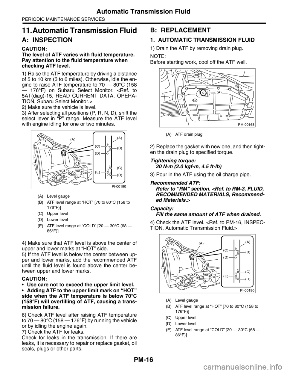
1) Raise the ATF temperature by driving a distance
of 5 to 10 km (3 to 6 miles). Otherwise, idle the en-
gine to raise ATF temperature to 70 — 80°C (158
— 176°F) on Subaru Select Monitor.
TION, Subaru Select Monitor.>
2) Make sure the vehicle is level.
3) After selecting all positions (P, R, N, D), shift the
select lever in “P” range. Measure the ATF level
with engine idling for one or two minutes.
4) Make sure that ATF level is above the center of
upper and lower marks at “HOT” side.
5) If the ATF level is below the center between up-
per and lower marks, add the recommended ATF
until the fluid level is found above the center be-
tween upper and lower marks.
CAUTION:
•Use care not to exceed the upper limit level.
•Adding ATF to the upper limit mark on “HOT”
side when the ATF temperature is below 70°C
(158°F) will overfilling of ATF, causing a trans-
mission failure.
6) Check ATF level after raising ATF temperature
to 70 — 80°C (158 — 176°F) by running the vehicle
or by idling the engine again.
7) Check the ATF for leaks.
Check for leaks in the transmission. If there are
leaks, it is necessary to repair or replace gasket, oil
seals, plugs or other parts.
B: REPLACEMENT
1. AUTOMATIC TRANSMISSION FLUID
1) Drain the ATF by removing drain plug.
NOTE:
Before starting work, cool off the ATF well.
2) Replace the gasket with new one, and then tight-
en the drain plug to specified torque.
Tightening torque:
20 N·m (2.0 kgf-m, 4.5 ft-lb)
3) Pour in the ATF using the oil charge pipe.
Recommended ATF:
Refer to “RM” section.
ed Materials.>
Capacity:
Fill the same amount of ATF when drained.
4) Check the ATF level.
(A) Level gauge
(B) ATF level range at “HOT” [70 to 80°C (158 to
176°F)]
(C) Upper level
(D) Lower level
(E) ATF level range at “COLD” [20 — 30°C (68 —
86°F)]
PI-00190
(A)
(C)
(D)
(E)(D)
(C)
(B)
(A)
F
L
F
HOT
LCOLD
(A) ATF drain plug
(A) Level gauge
(B) ATF level range at “HOT” [70 to 80°C (158 to
176°F)]
(C) Upper level
(D) Lower level
(E) ATF level range at “COLD” [20 — 30°C (68 —
86°F)]
PM-00168
(A)
PI-00190
(A)
(C)
(D)
(E)(D)
(C)
(B)
(A)
F
L
F
HOT
LCOLD
Page 2018 of 2453
5AT-2
General Description
AUTOMATIC TRANSMISSION
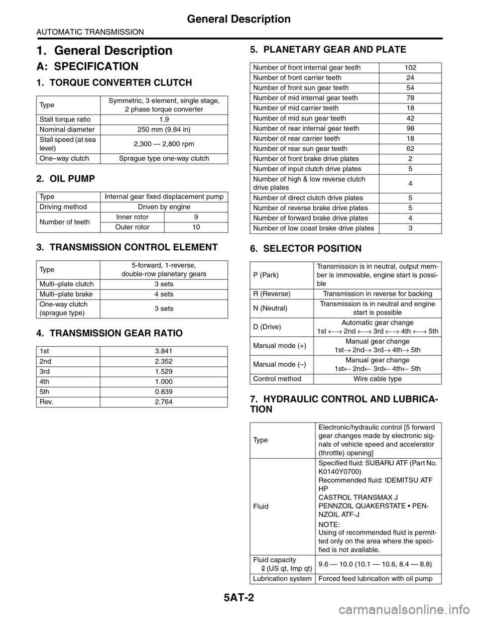
1. General Description
A: SPECIFICATION
1. TORQUE CONVERTER CLUTCH
2. OIL PUMP
3. TRANSMISSION CONTROL ELEMENT
4. TRANSMISSION GEAR RATIO
5. PLANETARY GEAR AND PLATE
6. SELECTOR POSITION
7. HYDRAULIC CONTROL AND LUBRICA-
TION
Ty p eSymmetric, 3 element, single stage,
2 phase torque converter
Stall torque ratio 1.9
Nominal diameter 250 mm (9.84 in)
Stall speed (at sea
level)2,300 — 2,800 rpm
One–way clutch Sprague type one-way clutch
Ty p e I n t e r n a l g e a r f i x e d d i s p l a c e m e n t p u m p
Driving method Driven by engine
Number of teethInner rotor 9
Outer rotor 10
Ty p e5-forward, 1-reverse,
double-row planetary gears
Multi–plate clutch 3 sets
Multi–plate brake 4 sets
One-way clutch
(sprague type)3 sets
1st 3.841
2nd 2.352
3rd 1.529
4th 1.000
5th 0.839
Rev. 2.764
Number of front internal gear teeth 102
Number of front carrier teeth 24
Number of front sun gear teeth 54
Number of mid internal gear teeth 78
Number of mid carrier teeth 18
Number of mid sun gear teeth 42
Number of rear internal gear teeth 98
Number of rear carrier teeth 18
Number of rear sun gear teeth 62
Number of front brake drive plates 2
Number of input clutch drive plates 5
Number of high & low reverse clutch
drive plates4
Number of direct clutch drive plates 5
Number of reverse brake drive plates 5
Number of forward brake drive plates 4
Number of low coast brake drive plates 3
P (Park)
Tr a n s m i s s i o n i s i n n e u t r a l , o u t p u t m e m -
ber is immovable, engine start is possi-
ble
R (Reverse) Transmission in reverse for backing
N (Neutral)Tr a n s m i s s i o n i s i n n e u t r a l a n d e n g i n e
start is possible
D (Drive)Automatic gear change
1st ←→ 2nd ←→ 3rd ←→ 4th ←→ 5th
Manual mode (+)Manual gear change
1st→ 2nd→ 3rd→ 4th→ 5th
Manual mode (–)Manual gear change
1st← 2nd← 3rd← 4th← 5th
Control method Wire cable type
Ty p e
Electronic/hydraulic control [5 forward
gear changes made by electronic sig-
nals of vehicle speed and accelerator
(throttle) opening]
Fluid
Specified fluid: SUBARU ATF (Part No.
K0140Y0700)
Recommended fluid: IDEMITSU ATF
HP
CASTROL TRANSMAX J
PENNZOIL QUAKERSTATE • PEN-
NZOIL ATF-J
NOTE:
Using of recommended fluid is permit-
ted only on the area where the speci-
fied is not available.
Fluid capacity
2(US qt, Imp qt)9.6 — 10.0 (10.1 — 10.6, 8.4 — 8.8)
Lubrication system Forced feed lubrication with oil pump