2009 SUBARU TRIBECA steering wheel adjustment
[x] Cancel search: steering wheel adjustmentPage 916 of 2453

PS-36
Steering Gearbox
POWER ASSISTED SYSTEM (POWER STEERING)
1) Lift-up the vehicle.
2) If a fluid leak is found, clean the fluid completely
from the suspect area, and turn the steering wheel
approx. 30 to 40 times to the left and right from lock
to lock, with the engine running, and check again
for leaks immediately, and also after a few hours
have passed.
3) Cause and solution for oil leakage from “a”
The oil seal is damaged. Replace the valve assem-
bly with a new one.
4) Cause and solution for oil leakage from “b”.
The torsion bar O–ring is damaged. Replace the
valve assembly with a new one.
5) Cause and solution for oil leakage from “c”.
The oil seal is damaged. Replace the valve assem-
bly or oil seal with a new one.
6) Cause and solution for oil leakage from “d”.
The pipe is damaged. Replace the faulty pipe or O-
ring.
7) Cause and solution for oil leakage from “g”.
The hose is damaged. Replace the hose with a
new one.
8) If leak is other than a, b, c, d or g, or if oil is leak-
ing from gearbox, move the right and left boots to-
ward tie-rod end side, respectively, with the
gearbox mounted to the vehicle, and remove fluid
from surrounding portions. Then, turn the steering
wheel from lock to lock about thirty to forty times
with the engine running, and make comparison of
the leaked portion immediately after and several
hours after this operation.
(1) Leakage from “e”
The cylinder seal is damaged. Replace the rack
bushing with a new one.
(2) Leakage from “f”
There are two possible causes. Perform the fol-
lowing step first. Remove the pipe assembly B
from the valve housing, and close the circuit us-
ing ST.
ST 926420000 PLUG
Turn the steering wheel from lock to lock ap-
prox. 30 to 40 times with the engine running,
then inspect the leaked portion immediately af-
ter and several hours after this operation.
•If leakage from “f” is noted again:
The oil seal of pinion & valve assembly is dam-
aged. Replace the pinion & valve assembly with a
new one. Or replace the oil seal and the parts that
are damaged during disassembly with new ones.
•If oil stops leaking from “f”:
The oil seal of rack housing is damaged. Replace
the oil seal and parts that are damaged during dis-
assembly with new ones.
F: ADJUSTMENT
1) Adjust the front toe.
Standard of front toe:
IN 3 — OUT 3 mm (IN 0.12 — OUT 0.12 in)
2) Adjust the steering angle of the wheels.
Specification of steering angle:
3) If the steering wheel spokes are not horizontal
when wheels are set in the straight ahead position,
or error is more than 5° on the periphery of the
steering wheel, correctly re-install the steering
wheel.
4) If the steering wheel spokes are not horizontal
with vehicle set in the straight ahead position after
this adjustment, correct it by turning the right and
left tie–rods in the opposite direction from each oth-
er by the same angle.
(1) Lock nut
Inner wheel 37.0°±1.5°
Outer wheel 32.0°±1.5°
(1) Within 5°
PS-00107
PS-00513
(1)
Page 930 of 2453

PS-50
General Diagnostic Table
POWER ASSISTED SYSTEM (POWER STEERING)
1. NOISE & VIBRATION
CAUTION:
Do not keep the relief valve operated over five seconds at any time or inner parts of the oil pump may
be damaged due to rapid increase of fluid temperature.
NOTE:
•A screeching noise may be heard immediately after the engine start in extremely cold conditions. In this
case, if the noise goes off during warm-up there is no abnormal function in the system. This is due to the fluid
characteristics in extremely cold condition.
•The oil pump normally makes a small whining noise due to its mechanism. Even if a noise is heard when
steering wheel is turned at stand still, there is no abnormal function in the system provided that the noise
eliminates when the vehicle is driving.
•When turning the steering wheel with the brake applied when the vehicle is parked, a screeching noise
may be generated by the brake disc and pads. This is not a fault in the steering system.
•There may be a small vibration around the steering devices when turning the steering wheel at standstill,
even though the component parts are operating properly.
Hydraulic systems are likely to generate this kind of vibration as well as working noise and fluid noise be-
cause of combined conditions, i.e., road surface and tire surface, engine speed and turning speed of steering
wheel, fluid temperature and braking condition.
These conditions do not indicate a problem in the system.
Confirm vibration for an AT model, by applying the parking brake on a concrete surface, shifting into the “D”
range, and turning the steering wheel repeatedly from slow to rapid, step by step.
Tr o u b l e P o s s i b l e c a u s e C o r r e c t i v e a c t i o n
Hiss noise (continuous)
While engine is running.
Relief valve emits operating sound when steering wheel is
completely turned in either direction. (Do not keep this
condition over five seconds.)
Normal
Relief valve emits operating sound when steering wheel is
not turned. This means that the relief valve is defective. Replace the oil pump.
Rattling noise (intermittent)
While engine is running.
Interference with adjacent parts
Check the clearance.
Correct if necessary.
Loosened installation of oil pump, oil tank, pump bracket,
gearbox or crossmemberRetighten.
Loose oil pump pulley or other pulley(s) Retighten.
Looseness of linkage, play of steering, improper tightening
(looseness) of suspension joint or steering columnRetighten or replace.
Sound generates from the inside of gearbox or oil pump.Replace faulty parts in the gear-
box or oil pump.
Knocking
When turning steering wheel in
both directions with small angle
repeatedly at engine ON or OFF.
Excessive backlash
Loosened lock nut for adjusting backlashAdjust and retighten.
Insufficient tightening or play in the tie–rod or tie–rod end Retighten or replace.
Grinding noise (continuous)
While engine is running.
Air in vane pump
Inspect and retighten the fluid
line connection.
Refill the fluid and vent air.
Va n e p u m p s e i z i n g R e p l a c e t h e o i l p u m p.
Oil pump pulley bearing seized Replace the oil pump.
Folded hose, flattened pipe Replace.
Squeal, squeak (intermittent or
continuous)
While engine is running.
Improper adjustment of pulley belt
Damaged or over tensioned pulley belt
Unequal length of pulley belts
Adjust or replace.
(Replace two belts as a set.)
Runout or dirty V–groove surface of oil pump pulley Clean or replace.
Page 932 of 2453

PS-52
General Diagnostic Table
POWER ASSISTED SYSTEM (POWER STEERING)
2. MEASUREMENT OF STEERING EFFORT
Step Check Yes No
1CHECK STEERING EFFORT.
1) Stop the vehicle on paved road.
2) Start the engine.
3) Run the engine at idle.
4) Install a spring scale on the steering wheel.
5) Pull the spring scale at a right angle to the
steering wheel, and measure both right and left
steering wheel efforts.
NOTE:When turning the steering more quickly than
necessary from a direction to the other direction
at an engine speed over 2,000 rpm, steering ef-
fort may be heavy. This is caused by flow char-
acteristic of the fluid in the oil pump and is not a
defect.
Is the steering effort less than
29.4 N (3.0 kgf, 6.6 lb)?
Go to step 2.Adjust the back-
lash.
2CHECK STEERING EFFORT.
1) Stop the engine.
2) Pull the spring scale at a right angle to the
steering wheel, and measure both right and left
steering wheel efforts.
Is the steering effort less than
294.2 N (30 kgf, 66.2 lb)?
Go to step 3.Perform the
adjustment.
3CHECK STEERING WHEEL EFFORT.
1) Remove the universal joint.
2) Measure the steering wheel effort.
Is steering effort less than 2.26
N (0.23 kgf, 0.51 lb)?
Go to step 4.Check, adjust and
replace if neces-
sary.
4CHECK STEERING WHEEL EFFORT.
Measure the steering wheel effort.
Is the difference of steering
effort between right and left
less than 20%?
Go to step 5.Check, adjust and
replace if neces-
sary.
5CHECK UNIVERSAL JOINT.
Measure the swing torque of the joint (yoke of
steering column side).
Is the swing torque of the uni-
versal joint less than 7.3 N
(0.74 kgf, 1.64 lb)?
Go to step 6.Replace with a
new part.
6CHECK UNIVERSAL JOINT.
Measure the swing torque of the joint (yoke of
gearbox side).
Is the swing torque of the uni-
versal joint less than 3.8 N
(0.39 kgf, 0.86 lb)?
Go to step 7.Replace with a
new part.
7CHECK FRONT WHEEL.
Check the front wheels.
Does the front wheels have
unsteady revolution or rattling,
or does the brake drag?
Inspect, readjust
and replace if nec-
essary.
Go to step 8.
8CHECK TIE–ROD ENDS.
Remove the tie–rod ends.
If the tie-rod ends of suspen-
sion have unsteady revolution
or rattling?
Inspect and
replace if neces-
sary.
Go to step 9.
9BALL JOINT CHECK.
Remove the ball joint.
If the ball joints of suspension
have unsteady revolution or
rattling?
Inspect and
replace if neces-
sary.
Go to step 10.
10 CHECK GEARBOX.
Measure the rotating of gearbox.
box.>
Is the rotating resistance of
steering gearbox less than
10.5 N (1.1 kgf, 2.4 lb)? Is the
difference between right and
left sides less than 20%?
Go to step 11.Readjust the back-
lash, and if ineffec-
tive, replace the
faulty par ts.
11 CHECK GEARBOX.
Measure the sliding of gearbox.
Is the sliding resistance of
steering gearbox less than 400
N (41 kgf, 90 lb)? Is the differ-
ence between the right and left
sliding resistance less than
20%?
Steering effort is
normal.
Readjust the back-
lash, and if ineffec-
tive, replace the
faulty par ts.
Page 1069 of 2453

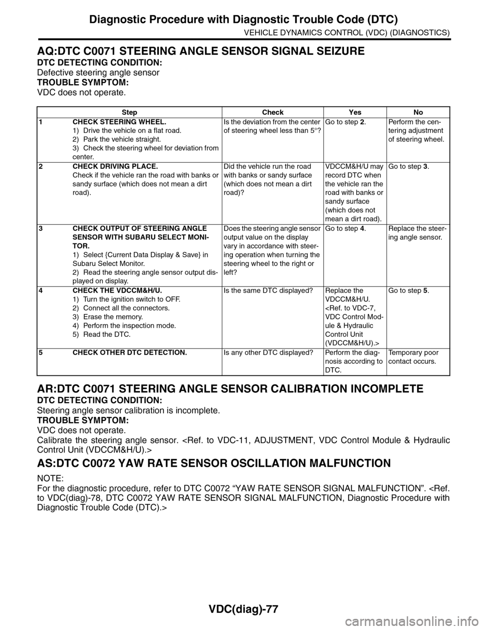
VDC(diag)-77
Diagnostic Procedure with Diagnostic Trouble Code (DTC)
VEHICLE DYNAMICS CONTROL (VDC) (DIAGNOSTICS)
AQ:DTC C0071 STEERING ANGLE SENSOR SIGNAL SEIZURE
DTC DETECTING CONDITION:
Defective steering angle sensor
TROUBLE SYMPTOM:
VDC does not operate.
AR:DTC C0071 STEERING ANGLE SENSOR CALIBRATION INCOMPLETE
DTC DETECTING CONDITION:
Steering angle sensor calibration is incomplete.
TROUBLE SYMPTOM:
VDC does not operate.
Calibrate the steering angle sensor.
AS:DTC C0072 YAW RATE SENSOR OSCILLATION MALFUNCTION
NOTE:
For the diagnostic procedure, refer to DTC C0072 “YAW RATE SENSOR SIGNAL MALFUNCTION”.
Diagnostic Trouble Code (DTC).>
Step Check Yes No
1CHECK STEERING WHEEL.
1) Drive the vehicle on a flat road.
2) Park the vehicle straight.
3) Check the steering wheel for deviation from
center.
Is the deviation from the center
of steering wheel less than 5°?
Go to step 2.Perform the cen-
tering adjustment
of steering wheel.
2CHECK DRIVING PLACE.
Check if the vehicle ran the road with banks or
sandy surface (which does not mean a dirt
road).
Did the vehicle run the road
with banks or sandy surface
(which does not mean a dirt
road)?
VDCCM&H/U may
record DTC when
the vehicle ran the
road with banks or
sandy surface
(which does not
mean a dirt road).
Go to step 3.
3CHECK OUTPUT OF STEERING ANGLE
SENSOR WITH SUBARU SELECT MONI-
TOR.
1) Select {Current Data Display & Save} in
Subaru Select Monitor.
2) Read the steering angle sensor output dis-
played on display.
Does the steering angle sensor
output value on the display
var y in accordance with steer-
ing operation when turning the
steering wheel to the right or
left?
Go to step 4.Replace the steer-
ing angle sensor.
4CHECK THE VDCCM&H/U.
1) Turn the ignition switch to OFF.
2) Connect all the connectors.
3) Erase the memory.
4) Perform the inspection mode.
5) Read the DTC.
Is the same DTC displayed? Replace the
VDCCM&H/U.
ule & Hydraulic
Control Unit
(VDCCM&H/U).>
Go to step 5.
5CHECK OTHER DTC DETECTION.Is any other DTC displayed? Perform the diag-
nosis according to
DTC.
Te m p o r a r y p o o r
contact occurs.
Page 1092 of 2453

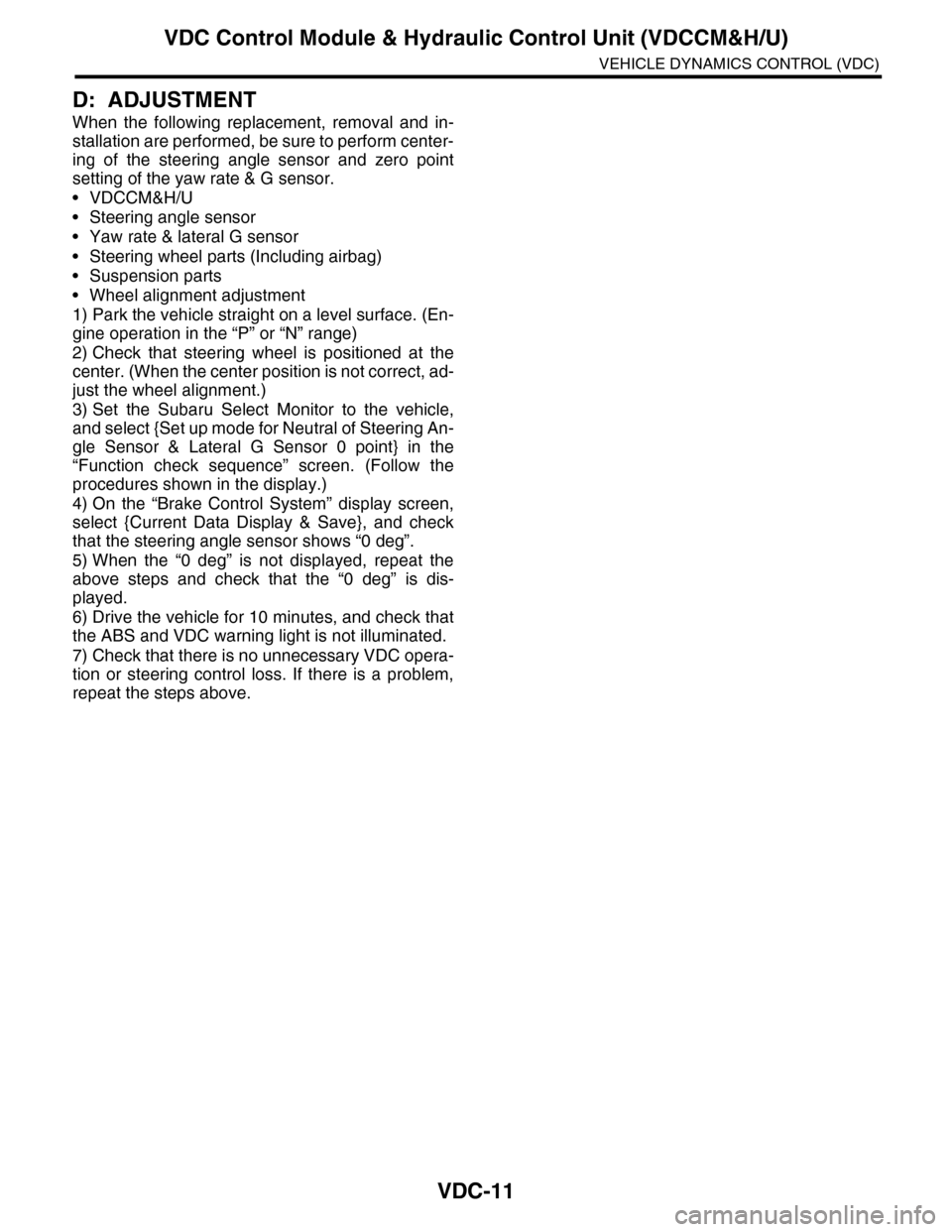
VDC-11
VDC Control Module & Hydraulic Control Unit (VDCCM&H/U)
VEHICLE DYNAMICS CONTROL (VDC)
D: ADJUSTMENT
When the following replacement, removal and in-
stallation are performed, be sure to perform center-
ing of the steering angle sensor and zero point
setting of the yaw rate & G sensor.
•VDCCM&H/U
•Steering angle sensor
•Yaw rate & lateral G sensor
•Steering wheel parts (Including airbag)
•Suspension parts
•Wheel alignment adjustment
1) Park the vehicle straight on a level surface. (En-
gine operation in the “P” or “N” range)
2) Check that steering wheel is positioned at the
center. (When the center position is not correct, ad-
just the wheel alignment.)
3) Set the Subaru Select Monitor to the vehicle,
and select {Set up mode for Neutral of Steering An-
gle Sensor & Lateral G Sensor 0 point} in the
“Function check sequence” screen. (Follow the
procedures shown in the display.)
4) On the “Brake Control System” display screen,
select {Current Data Display & Save}, and check
that the steering angle sensor shows “0 deg”.
5) When the “0 deg” is not displayed, repeat the
above steps and check that the “0 deg” is dis-
played.
6) Drive the vehicle for 10 minutes, and check that
the ABS and VDC warning light is not illuminated.
7) Check that there is no unnecessary VDC opera-
tion or steering control loss. If there is a problem,
repeat the steps above.
Page 1100 of 2453

VDC-19
Steering Angle Sensor
VEHICLE DYNAMICS CONTROL (VDC)
6. Steering Angle Sensor
A: REPLACEMENT
CAUTION:
•Do not perform the removal except when the
replacement.
•When replacing more than three times, re-
place the combination switch as assembly to
protect the threads.
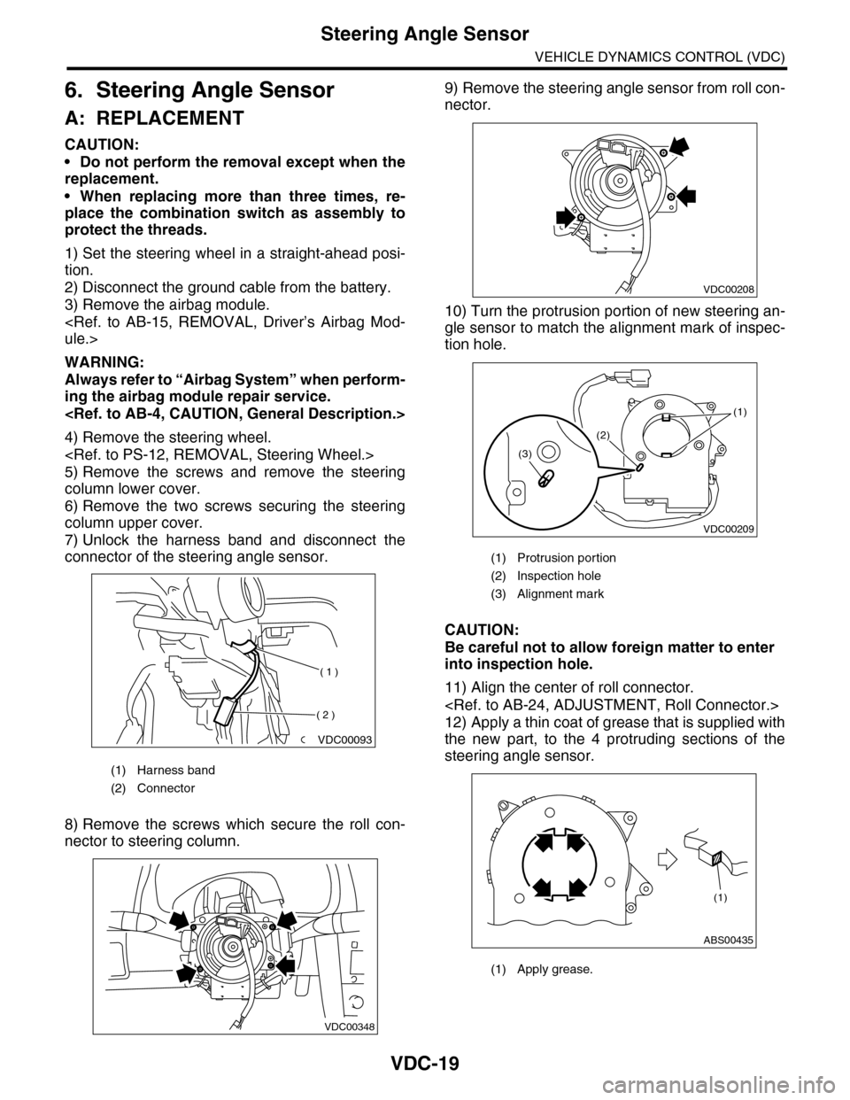
1) Set the steering wheel in a straight-ahead posi-
tion.
2) Disconnect the ground cable from the battery.
3) Remove the airbag module.
WARNING:
Always refer to “Airbag System” when perform-
ing the airbag module repair service.
4) Remove the steering wheel.
5) Remove the screws and remove the steering
column lower cover.
6) Remove the two screws securing the steering
column upper cover.
7) Unlock the harness band and disconnect the
connector of the steering angle sensor.
8) Remove the screws which secure the roll con-
nector to steering column.
9) Remove the steering angle sensor from roll con-
nector.
10) Turn the protrusion portion of new steering an-
gle sensor to match the alignment mark of inspec-
tion hole.
CAUTION:
Be careful not to allow foreign matter to enter
into inspection hole.
11) Align the center of roll connector.
12) Apply a thin coat of grease that is supplied with
the new part, to the 4 protruding sections of the
steering angle sensor.
(1) Harness band
(2) Connector
VDC00093
( 1 )
( 2 )
VDC00348
(1) Protrusion portion
(2) Inspection hole
(3) Alignment mark
(1) Apply grease.
VDC00208
VDC00209
(1)
(2)
(3)
ABS00435
(1)