2009 SUBARU TRIBECA steering wheel adjustment
[x] Cancel search: steering wheel adjustmentPage 5 of 2453

AB-6
General Description
AIRBAG SYSTEM
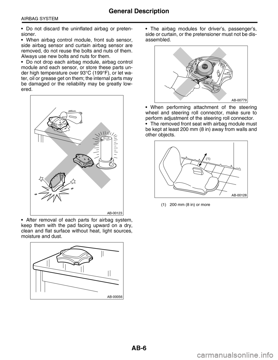
•Do not discard the uninflated airbag or preten-
sioner.
•When airbag control module, front sub sensor,
side airbag sensor and curtain airbag sensor are
removed, do not reuse the bolts and nuts of them.
Always use new bolts and nuts for them.
•Do not drop each airbag module, airbag control
module and each sensor, or store these parts un-
der high temperature over 93°C (199°F), or let wa-
ter, oil or grease get on them; the internal parts may
be damaged or the reliability may be greatly low-
ered.
•After removal of each parts for airbag system,
keep them with the pad facing upward on a dry,
clean and flat surface without heat, light sources,
moisture and dust.
•The airbag modules for driver’s, passenger’s,
side or curtain, or the pretensioner must not be dis-
assembled.
•When performing attachment of the steering
wheel and steering roll connector, make sure to
perform adjustment of the steering roll connector.
•The removed front seat with airbag module must
be kept at least 200 mm (8 in) away from walls and
other objects.
AB-00123
AB-00056
(1) 200 mm (8 in) or more
AB-00779
AB-00128
(1)
Page 23 of 2453

AB-24
Roll Connector
AIRBAG SYSTEM
11.Roll Connector
A: REMOVAL
1) Turn the ignition switch to OFF.
2) Disconnect the ground cable from battery and
wait for at least 20 seconds before starting work.
3) Remove the driver’s airbag module.
4) Remove the steering wheel.
5) Remove the steering column cover.
6) Remove the screws, and then remove the roll
connector.
B: INSTALLATION
1) Install in the reverse order of removal.
2) Before installing steering wheel, be sure to ad-
just the direction of roll connector with steering.
C: INSPECTION
Check for the following, and replace the damaged
parts with new parts.
•Combination switch and roll connector are
cracked or deformed.
D: ADJUSTMENT
1) Check that front wheels are positioned in straight
ahead direction.
2) Turn the roll connector pin (A) clockwise until it
stops.
3) Turn the roll connector pins (A) approx. 3.25
turns until “ ” marks are aligned.
AB-01273
AB-00594
(A)
Page 543 of 2453

LI-10
Combination Base Switch Assembly
LIGHTING SYSTEM
9. Combination Base Switch
Assembly
A: REMOVAL
1) Remove the driver’s airbag module.
2) Remove the steering wheel.
3) Remove the screws and remove the steering
column lower cover.
4) Remove the combination switch.
5) Remove the four screws and remove the roll
connector.
6) Remove the three screws.
7) Disconnect the connector and remove the com-
bination base switch assembly.
B: INSTALLATION
1) Install in the reverse order of removal.
2) Before installing steering wheel, be sure to ad-
just the direction of roll connector with steering.
C: INSPECTION
1. COMBINATION BASE SWITCH ASSEM-
BLY
Inspect the combination base switch assembly and
roll connector for cracks or deformation. If any
damage is found, replace with a new part.
2. PARKING SWITCH
Measure the resistance between parking switch
terminals.
SL-00258
LI-00271
Switch position Terminal No. Standard
OFF 2 and 4 Less than 1 Ω
ON 1 and 4 Less than 1 Ω
LI-00183
1234
Page 858 of 2453

FS-10
Wheel Alignment
FRONT SUSPENSION
4. STEERING ANGLE
•INSPECTION
•ADJUSTMENT
1) Turn the tie-rod to adjust the steering angle of
both inner and outer wheels.
2) Check the toe–in.
NOTE:
Correct the boot if it is twisted.
5. FRONT WHEEL TOE–IN
•INSPECTION
Toe-in:
0±3 mm (0±0.12 in)
1) Set the toe-in gauge in the position at wheel axis
center height behind the right and left front tires.
2) Place a mark at the center of both left and right
tires, and measure distance “A” between the
marks.
3) Move the vehicle forward to rotate the tires 180°.
NOTE:
Be sure to rotate the tires in the forward direction.
4) Measure distance “B” between the left and right
marks. Find toe–in using the following equation:
A – B = Toe–in
•ADJUSTMENT
When adjusting the toe-in, adjust it to the following
value.
Toe-in:
0±2 mm (0±0.08 in)
1) Check that the left and right wheel steering an-
gles are within specification.
2) Loosen the left and right side steering tie–rod
lock nuts.
3) Turn the left and right tie–rods by equal amounts
until the toe–in is at the specification.
Both the left and right tie–rods are right–hand
threaded. To increase toe–in, turn both tie–rods
clockwise by equal amount (viewing from the inside
of vehicle).
4) Tighten the tie–rod lock nut.
Tightening torque:
85 N·m (8.7 kgf-m, 62.7 ft-lb)
NOTE:
Check and correct the tie rod boot if twisted.
6. REAR WHEEL TOE–IN
•INSPECTION
Toe-in:
2±2 mm (0.08±0.08 in)
Refer to FRONT WHEEL TOE–IN for rear toe–in
inspection procedures.
Inner wheel Outer wheel
37.0°±1.5° 32.0°±1.5°
(1) Lock nut
FS-00014
(1)
FS-00015
AB
(1) Lock nut
FS-00014
(1)
Page 892 of 2453

PS-12
Steering Wheel
POWER ASSISTED SYSTEM (POWER STEERING)
2. Steering Wheel
A: REMOVAL
1) Disconnect the ground cable from the battery.
2) Set the tire to the straight–ahead position.
3) Remove the airbag module.
WARNING:
Always refer to “Air Bag System” before per-
forming service on the air bag modules.
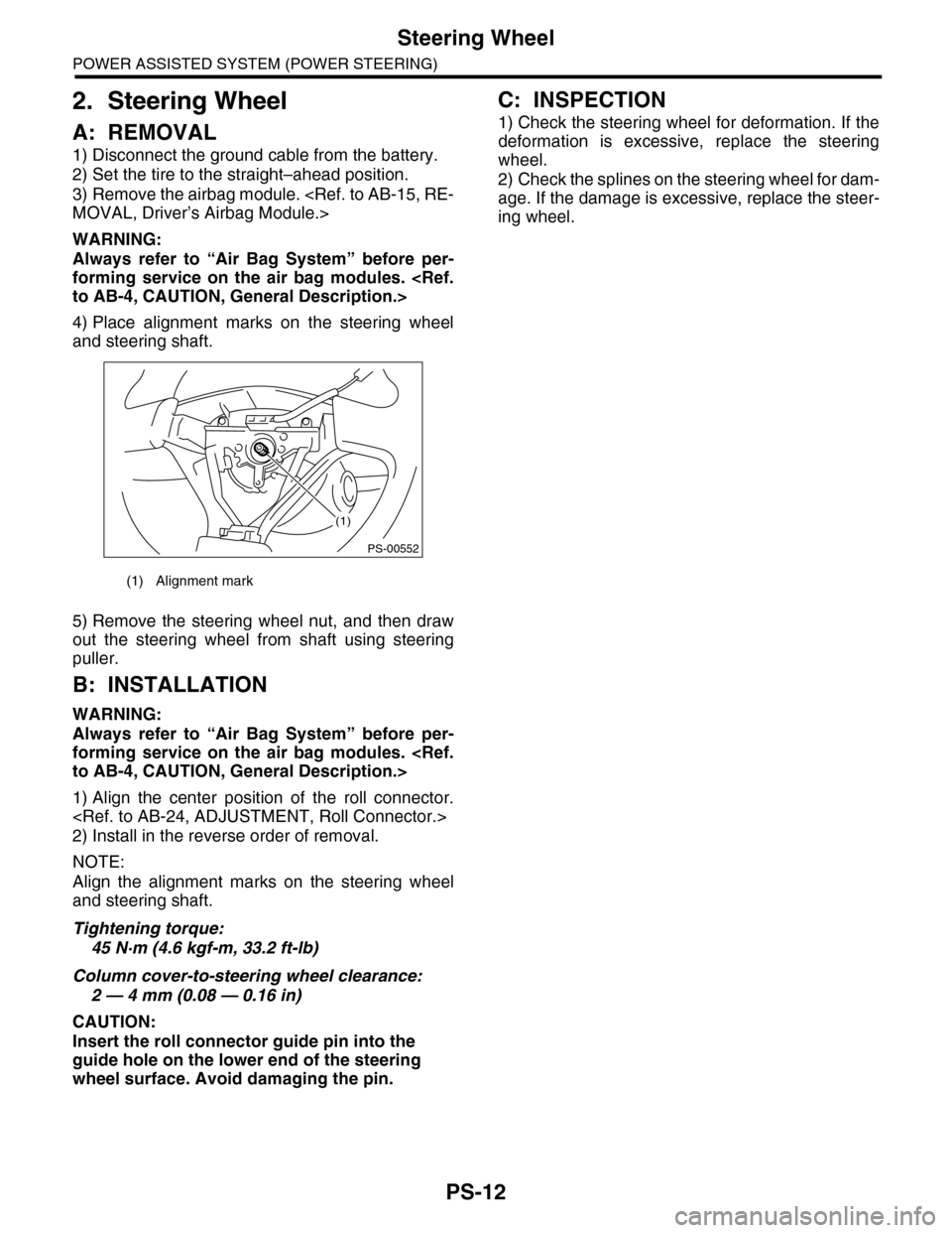
4) Place alignment marks on the steering wheel
and steering shaft.
5) Remove the steering wheel nut, and then draw
out the steering wheel from shaft using steering
puller.
B: INSTALLATION
WARNING:
Always refer to “Air Bag System” before per-
forming service on the air bag modules.
1) Align the center position of the roll connector.
2) Install in the reverse order of removal.
NOTE:
Align the alignment marks on the steering wheel
and steering shaft.
Tightening torque:
45 N·m (4.6 kgf-m, 33.2 ft-lb)
Column cover-to-steering wheel clearance:
2 — 4 mm (0.08 — 0.16 in)
CAUTION:
Insert the roll connector guide pin into the
guide hole on the lower end of the steering
wheel surface. Avoid damaging the pin.
C: INSPECTION
1) Check the steering wheel for deformation. If the
deformation is excessive, replace the steering
wheel.
2) Check the splines on the steering wheel for dam-
age. If the damage is excessive, replace the steer-
ing wheel.
(1) Alignment mark
(1)
PS-00552
Page 893 of 2453

PS-13
Universal Joint
POWER ASSISTED SYSTEM (POWER STEERING)
3. Universal Joint
A: REMOVAL
1) Remove the steering wheel.
2) Place alignment marks on universal joint.
3) Remove the universal joint bolt, and then re-
move the universal joint.
B: INSTALLATION
1) Align the cutout portion at serrated section of the
column shaft and yoke, then install the universal
joint into column shaft.
2) Install the universal joint to the serrations of
gearbox assembly by matching alignment marks.
3) Tighten the bolt.
Tightening torque:
24 N·m (2.4 kgf-m, 17.4 ft-lb)
CAUTION:
Excessively large tightening torque of univer-
sal joint bolts may lead to heavy steering wheel
operation.
Clearance between coupling of universal joint
to AT level gage:
15 mm (0.59 in) or more
4) Align the center position of the roll connector.
5) Install the steering wheel.
C: INSPECTION
Check for wear, damage or any other faults. Re-
place as necessary.
Service limit:
Universal joint play: 0 mm (0 in)
Maximum swing torque: 0.3 N (0.03 kgf, 0.07
lb)
Measure the swing torque of universal joint.
Service limit:
Maximum load: 3.8 N (0.39 kgf, 0.86 lb) or less
Service limit:
Maximum load: 3.8 N (0.39 kgf, 0.86 lb) or less
PS-00731
(1) Swing torque
(2) Play
(1) Yoke (Gearbox side)
(1) Yoke (Gearbox side)
PS-00033
(1)
(2)
PS-00034
PS-00035
Page 896 of 2453

PS-16
Tilt Steering Column
POWER ASSISTED SYSTEM (POWER STEERING)
B: INSTALLATION
1) Insert the end of the steering shaft into the toe
board.
2) With the tilt lever secured, tighten the steering
shaft mounting bolts under instrument panel.
Tightening torque:
25 N·m (2.5 kgf-m, 18.1 ft-lb)
3) Connect all the connectors under the instrument
panel.
4) Connect the airbag system connector at the har-
ness spool.
NOTE:
Make sure to apply double lock.
5) Install the instrument panel lower cover with tilt
lever held in the lowered position.
6) Install the universal joint.
7) Align the center position of the roll connector.
8) Install the steering wheel.
CAUTION:
Insert the roll connector guide pin into the
guide hole on lower end of steering wheel sur-
face to prevent damage.
C: DISASSEMBLY
Remove the two screws securing the upper steer-
ing column covers, and the two screws securing
the combination switch, and then remove related
parts.
D: ASSEMBLY
Insert the combination switch to the upper column
shaft, and install the upper column cover. Then
route the ignition key harness and combination
switch harness between the column cover mount-
ing bosses.
Tightening torque:
1.2 N·m (0.12 kgf-m, 0.9 ft-lb)
CAUTION:
Do not overtorque the screw.
E: INSPECTION
1. BASIC INSPECTION
Measure the overall length of steering column. If
not within specification, replace it.
Overall length L:
Specification
917.5 +1.3 mm –0.3 mm (36.12 +0.051 in –0.020 in )
2. INSPECTION OF AIRBAG SYSTEM
WARNING:
Refer to “Airbag System” for airbag inspection
procedure.
PS-00734
L
Page 899 of 2453

PS-19
Steering Gearbox
POWER ASSISTED SYSTEM (POWER STEERING)
6) After tightening the castle nut to the specified
tightening torque, tighten it further within 60° until
the cotter pin hole is aligned with slot in the nut. Fit
the cotter pin into the nut, and then bend the pin to
lock.
7) Install the front stabilizer.
8) Install the front crossmember support plate and
jack-up plate.
9) Install the front exhaust pipe assembly. (Non–
turbo model)
10) Install the under cover.
11) Install the front wheels.
12) Tighten the wheel nuts to the specified torque.
Tightening torque:
110 N·m (11.2 kgf-m, 81.1 ft-lb)
13) Lower the vehicle.
14) Remove the steering wheel.
15) Align the center position of the roll connector.
16) Install the steering wheel.
17) Connect the ground cable to the battery.
18) Pour fluid into the oil tank, and bleed air.
19) Check for fluid leaks.
20) Check the fluid level in oil tank.
21) After adjusting toe-in and steering angle, tight-
en the lock nut on tie-rod end.
Tightening torque:
85 N·m (8.7 kgf-m, 62.7 ft-lb)
NOTE:
When adjusting toe-in, hold the boot as shown to
prevent it from being rotated or twisted. If it be-
comes twisted, straighten it.
C: DISASSEMBLY
1. RACK HOUSING ASSEMBLY
1) Disconnect the four pipes from gearbox.
NOTE:
Remove the pipes C and D, which are fixed to
clamp plate, as a unit.
2) Secure the gearbox removed from vehicle in a
vise using ST.
ST1 926200000 STAND
ST2 34199AG000 BOSS D
CAUTION:
Secure the gearbox in a vise using ST as shown
in the figure. Do not secure the gearbox without
this ST.
3) Remove the tie-rod end and lock nut from gear-
box.
(A) Cotter pin
(B) Castle nut
(C) Tie–rod end
DS-00042
(C)
(B)
(A)
(1) Clamp
PS-00051
PS-00492
(1)
ST1
ST2