Page 2085 of 2453
5AT-69
Reduction Driven Gear
AUTOMATIC TRANSMISSION
4) Using the ST, remove the parking gear.
ST 18767AA000 REMOVER
D: ASSEMBLY
1) Using the ST, install the parking gear.
ST 499755602 PRESS
2) Install the snap ring.
3) Install the new ball bearing to reduction driven
gear using press.
ST 18654AA000 INSTALLER
4) Install the ball bearing on the reverse side with
the same procedure as step 3).
ST 18654AA000 INSTALLER
E: INSPECTION
Make sure the ball bearing and gear is not de-
formed or damaged.
F: ADJUSTMENT
1) Using the ST, measure the height “A” from the
AT main case mating surface to ball bearing outer
ring contact surface.
ST 499575400 GAUGE
2) Using the ST, measure the depth “B”, which is
from mating surface of extension case to ball bear-
ing outer ring contact surface.
ST 499575400 GAUGE
(A) Ball bearing 1
AT-03265
ST
ST
AT-03264
AT-03267
ST
AT-03268
ST
AT-03269
ST
A
AT-03270
ST
B
Page 2100 of 2453

5AT-84
Drive Pinion Shaft Assembly
AUTOMATIC TRANSMISSION
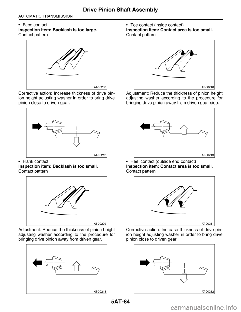
•Face contact
Inspection item: Backlash is too large.
Contact pattern
Corrective action: Increase thickness of drive pin-
ion height adjusting washer in order to bring drive
pinion close to driven gear.
•Flank contact
Inspection item: Backlash is too small.
Contact pattern
Adjustment: Reduce the thickness of pinion height
adjusting washer according to the procedure for
bringing drive pinion away from driven gear.
•Toe contact (inside contact)
Inspection item: Contact area is too small.
Contact pattern
Adjustment: Reduce the thickness of pinion height
adjusting washer according to the procedure for
bringing drive pinion away from driven gear side.
•Heel contact (outside end contact)
Inspection item: Contact area is too small.
Contact pattern
Corrective action: Increase thickness of drive pin-
ion height adjusting washer in order to bring drive
pinion close to driven gear.
AT-00208
AT-00212
AT-00209
AT-00213
AT-00210
AT-00213
AT-00211
AT-00212
Page 2115 of 2453

5AT-99
AT Main Case
AUTOMATIC TRANSMISSION
F: ADJUSTMENT
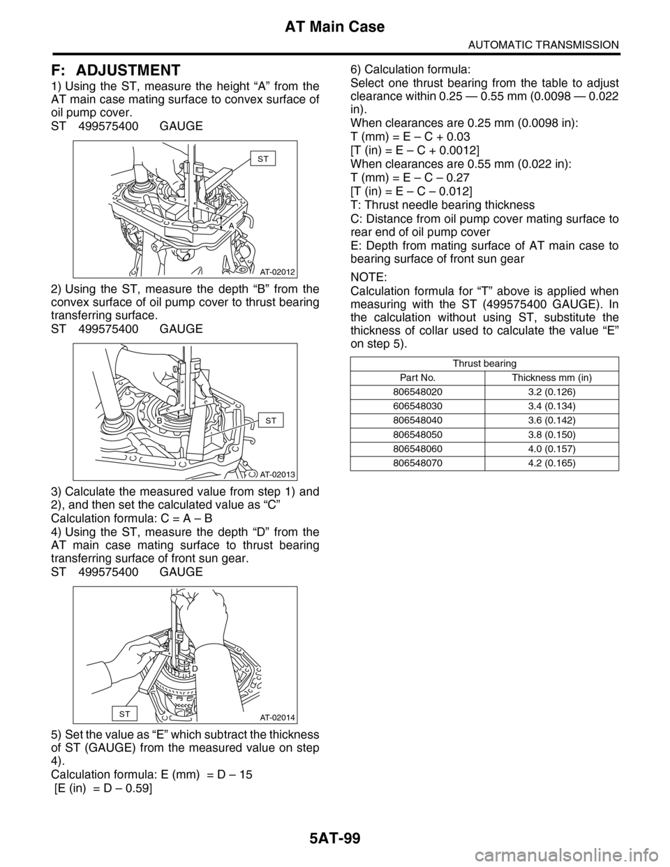
1) Using the ST, measure the height “A” from the
AT main case mating surface to convex surface of
oil pump cover.
ST 499575400 GAUGE
2) Using the ST, measure the depth “B” from the
convex surface of oil pump cover to thrust bearing
transferring surface.
ST 499575400 GAUGE
3) Calculate the measured value from step 1) and
2), and then set the calculated value as “C”
Calculation formula: C = A – B
4) Using the ST, measure the depth “D” from the
AT main case mating surface to thrust bearing
transferring surface of front sun gear.
ST 499575400 GAUGE
5) Set the value as “E” which subtract the thickness
of ST (GAUGE) from the measured value on step
4).
Calculation formula: E (mm) = D – 15
[E (in) = D – 0.59]
6) Calculation formula:
Select one thrust bearing from the table to adjust
clearance within 0.25 — 0.55 mm (0.0098 — 0.022
in).
When clearances are 0.25 mm (0.0098 in):
T (mm) = E – C + 0.03
[T (in) = E – C + 0.0012]
When clearances are 0.55 mm (0.022 in):
T (mm) = E – C – 0.27
[T (in) = E – C – 0.012]
T: Thrust needle bearing thickness
C: Distance from oil pump cover mating surface to
rear end of oil pump cover
E: Depth from mating surface of AT main case to
bearing surface of front sun gear
NOTE:
Calculation formula for “T” above is applied when
measuring with the ST (499575400 GAUGE). In
the calculation without using ST, substitute the
thickness of collar used to calculate the value “E”
on step 5).
AT-02012
ST
A
AT-02013
STB
AT-02014ST
D
Thrust bearing
Par t N o. Thickness mm (in)
806548020 3.2 (0.126)
606548030 3.4 (0.134)
806548040 3.6 (0.142)
806548050 3.8 (0.150)
806548060 4.0 (0.157)
806548070 4.2 (0.165)