2009 SUBARU TRIBECA brakes
[x] Cancel search: brakesPage 1024 of 2453
VDC(diag)-32
Warning Light Illumination Pattern
VEHICLE DYNAMICS CONTROL (VDC) (DIAGNOSTICS)
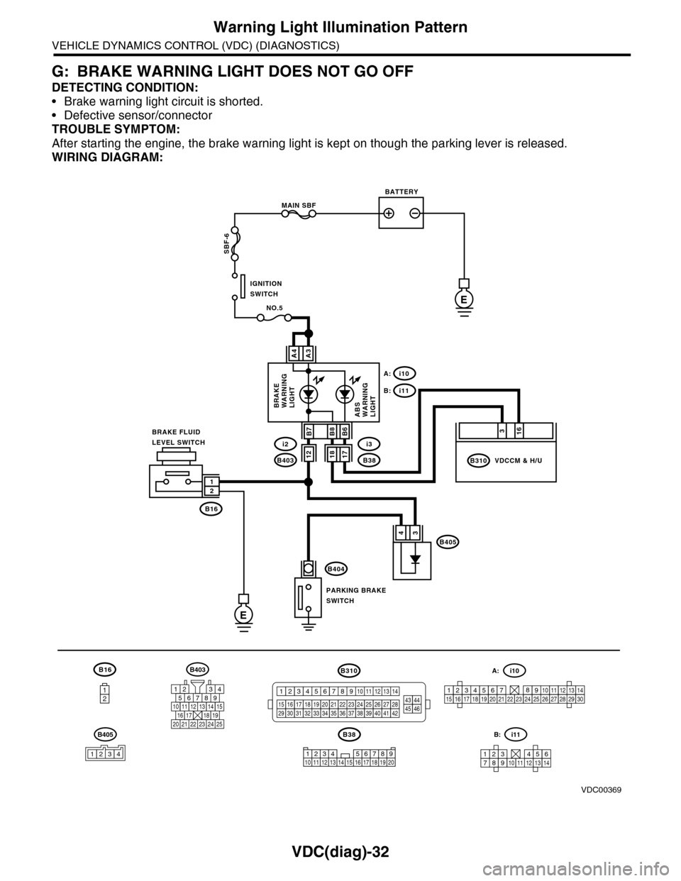
G: BRAKE WARNING LIGHT DOES NOT GO OFF
DETECTING CONDITION:
•Brake warning light circuit is shorted.
•Defective sensor/connector
TROUBLE SYMPTOM:
After starting the engine, the brake warning light is kept on though the parking lever is released.
WIRING DIAGRAM:
B16
12
B38
E
MAIN SBF
SBF-6
E
NO.5
B16
B404
A3A4
12
34B405
1234 5678910 11 12 13 14 15 16 17 18 19 20
BATTERY
IGNITIONSWITCH
BRAKE FLUIDLEVEL SWITCH
PARKING BRAKESWITCH
BRAKEWARNINGLIGHTABSWARNINGLIGHT
316
B310B38
i3
i10A:
i11B:
VDCCM & H/U
B8
1817B403
i2B7B6
VDC00369
12
B405
1234
B403
567821943
10
2422 23 25
1112131415161718192021
B310
1234
1516171819202122232425262728293031323334353637383940414245464344568910 11 12 13 147
1234567891011121314
i11B:
123456789101112131415161718192021222324252627282930
i10A:
Page 1198 of 2453
EN(H6DO)(diag)-37
Inspection Mode
ENGINE (DIAGNOSTICS)
1. PREPARATION FOR THE INSPECTION
MODE
1) Check battery voltage is more than 12 V and fuel
remains half [20 to 40 2 (5.3 to 10.6 US gal, 4.4 to
8.8 Imp gal)].
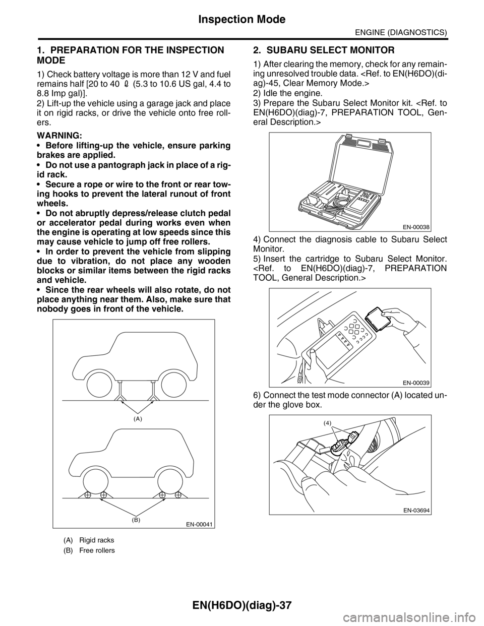
2) Lift-up the vehicle using a garage jack and place
it on rigid racks, or drive the vehicle onto free roll-
ers.
WARNING:
•Before lifting-up the vehicle, ensure parking
brakes are applied.
•Do not use a pantograph jack in place of a rig-
id rack.
•Secure a rope or wire to the front or rear tow-
ing hooks to prevent the lateral runout of front
wheels.
•Do not abruptly depress/release clutch pedal
or accelerator pedal during works even when
the engine is operating at low speeds since this
may cause vehicle to jump off free rollers.
•In order to prevent the vehicle from slipping
due to vibration, do not place any wooden
blocks or similar items between the rigid racks
and vehicle.
•Since the rear wheels will also rotate, do not
place anything near them. Also, make sure that
nobody goes in front of the vehicle.
2. SUBARU SELECT MONITOR
1) After clearing the memory, check for any remain-
ing unresolved trouble data.
2) Idle the engine.
3) Prepare the Subaru Select Monitor kit.
eral Description.>
4) Connect the diagnosis cable to Subaru Select
Monitor.
5) Insert the cartridge to Subaru Select Monitor.
6) Connect the test mode connector (A) located un-
der the glove box.
(A) Rigid racks
(B) Free rollers
EN-00041
(A)
(B)
EN-00038
EN-00039
EN-03694
(4)
Page 2003 of 2453
PM-20
Brake Line
PERIODIC MAINTENANCE SERVICES
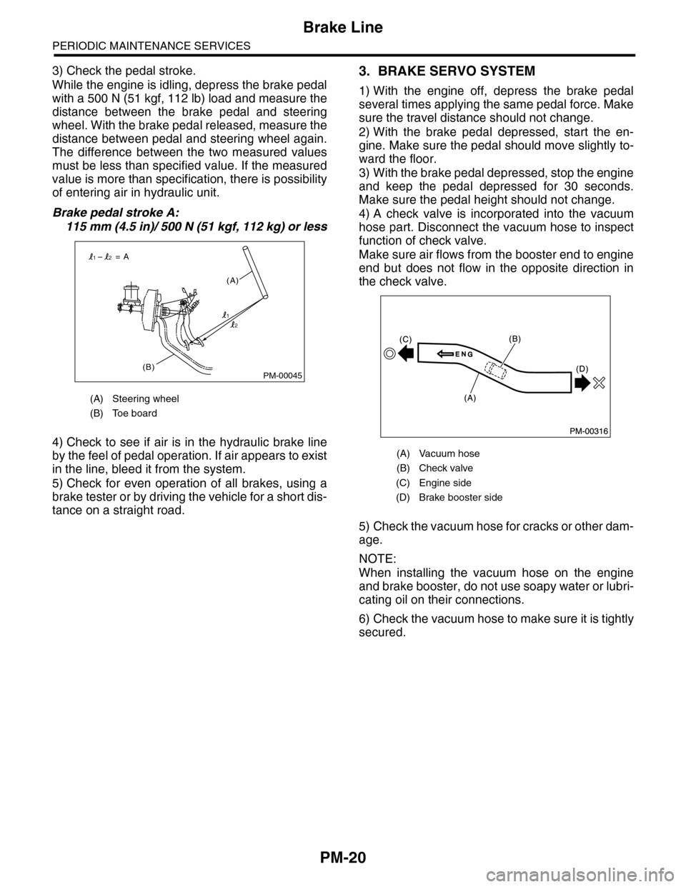
3) Check the pedal stroke.
While the engine is idling, depress the brake pedal
with a 500 N (51 kgf, 112 lb) load and measure the
distance between the brake pedal and steering
wheel. With the brake pedal released, measure the
distance between pedal and steering wheel again.
The difference between the two measured values
must be less than specified value. If the measured
value is more than specification, there is possibility
of entering air in hydraulic unit.
Brake pedal stroke A:
115 mm (4.5 in)/ 500 N (51 kgf, 112 kg) or less
4) Check to see if air is in the hydraulic brake line
by the feel of pedal operation. If air appears to exist
in the line, bleed it from the system.
5) Check for even operation of all brakes, using a
brake tester or by driving the vehicle for a short dis-
tance on a straight road.
3. BRAKE SERVO SYSTEM
1) With the engine off, depress the brake pedal
several times applying the same pedal force. Make
sure the travel distance should not change.
2) With the brake pedal depressed, start the en-
gine. Make sure the pedal should move slightly to-
ward the floor.
3) With the brake pedal depressed, stop the engine
and keep the pedal depressed for 30 seconds.
Make sure the pedal height should not change.
4) A check valve is incorporated into the vacuum
hose part. Disconnect the vacuum hose to inspect
function of check valve.
Make sure air flows from the booster end to engine
end but does not flow in the opposite direction in
the check valve.
5) Check the vacuum hose for cracks or other dam-
age.
NOTE:
When installing the vacuum hose on the engine
and brake booster, do not use soapy water or lubri-
cating oil on their connections.
6) Check the vacuum hose to make sure it is tightly
secured.
(A) Steering wheel
(B) Toe board
PM-00045(B)
(A)
= A
1
12
2
(A) Vacuum hose
(B) Check valve
(C) Engine side
(D) Brake booster side
Page 2004 of 2453
PM-21
Brake Fluid
PERIODIC MAINTENANCE SERVICES
14.Brake Fluid
A: REPLACEMENT
1) Either jack-up the vehicle and place a rigid rack
under it, or lift-up the vehicle.
2) Remove all the wheels.
3) Drain the brake fluid from master cylinder.
4) Refill the reservoir tank with recommended
brake fluid.
Recommended brake fluid:
Refer to “RM” section.
ed Materials.>
NOTE:
•Avoid mixing different brands of brake fluid to
prevent degrading the quality of fluid.
•Be careful not to allow dirt or dust to get into the
reservoir tank.
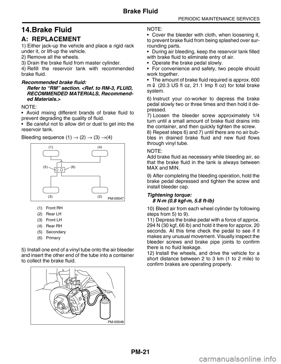
Bleeding sequence (1) → (2) → (3) →(4)
5) Install one end of a vinyl tube onto the air bleeder
and insert the other end of the tube into a container
to collect the brake fluid.
NOTE:
•Cover the bleeder with cloth, when loosening it,
to prevent brake fluid from being splashed over sur-
rounding parts.
•During air bleeding, keep the reservoir tank filled
with brake fluid to eliminate entry of air.
•Operate the brake pedal slowly.
•For convenience and safety, two people should
work together.
•The amount of brake fluid required is approx. 600
m2 (20.3 US fl oz, 21.1 Imp fl oz) for total brake
system.
6) Instruct your co-worker to depress the brake
pedal slowly two or three times and then hold it de-
pressed.
7) Loosen the bleeder screw approximately 1/4
turn until a small amount of brake fluid drains into
the container, and then quickly tighten the screw.
8) Repeat steps 6) and 7) until there are no air bub-
bles in drained brake fluid and new fluid flows
through vinyl tube.
NOTE:
Add brake fluid as necessary while bleeding air, so
that the brake fluid in the tank is always between
MAX and MIN.
9) After completing the bleeding operation, hold the
brake pedal depressed and tighten the screw and
install bleeder cap.
Tightening torque:
8 N·m (0.8 kgf-m, 5.8 ft-lb)
10) Bleed air from each wheel cylinder by following
steps from 5) to 9).
11) Depress the brake pedal with a force of approx.
294 N (30 kgf, 66 lb) and hold it there for approx. 20
seconds. At this time check the pedal to see if it
makes any unusual movement. Visually inspect the
bleeder screws and brake pipe joints to confirm
there is no fluid leakage.
12) Install the wheels, and drive the vehicle for a
short distance between 2 to 3 km (1 to 2 mile) to
confirm brakes are operating properly.
(1) Front RH
(2) Rear LH
(3) Front LH
(4) Rear RH
(5) Secondary
(6) Primary
(1) (4)
(2)(3)
(5) (6)
PM-00047
PM-00048
Page 2294 of 2453
WI-10
Basic Diagnostic Procedure
WIRING SYSTEM
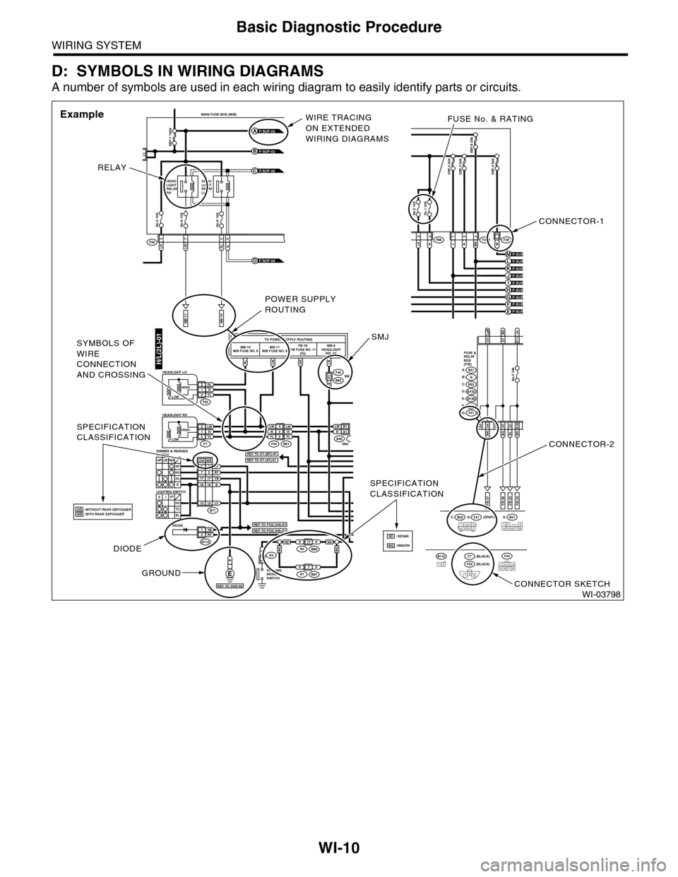
D: SYMBOLS IN WIRING DIAGRAMS
A number of symbols are used in each wiring diagram to easily identify parts or circuits.
WI-03798
LRLWRL3725
MAIN FUSE BOX (M/B)
MB-11MB-10
F39
P-SUP-02B
P-SUP-02A
P-SUP-02C
No.3 10ANo.9 15ANo.8 15A
SBF-1 100A
HEAD-LIGHTRELAYRH
HEAD-LIGHTRELAYLH
G
P-SUP-04D
H/L(2L)-01RLLWGRLB
TO POWER SUPPLY ROUTINGMB-10M/B FUSE NO. 8MB-11M/B FUSE NO. 9FB-16F/B FUSE NO. 11(IG)MB-5HEADLIGHTRELAY
LW 4R3YLLWRYL2
YB1RY2
LW2R1YL3
P
LW B 1RA1
F44
F45
F23
F7B61
B62
B
RL2R1YL3
B71
B112
LY8RY7YBB1716
3
1716
UPLOWPA S SHFHUHLE
SMJLB H1
B36SMJ
DIODE
: WITHOUT REAR DEFOGGER: WITH REAR DEFOGGER
PA R K I N GBRAKESWITCH
R4
OFFHCTCEL
LOWHIGH
HEADLIGHT RH
HEADLIGHT LH
LIGHTING SWITCH
DIMMER & PASSINGSWITCH
LOWHIGH
B51A:B52C:F41G: (GRAY)
(BLACK)(BLACK)
FB-37
D4D7BGD11
A2WR G4BLG1BR D10
FB-35FB-34
123456712345678
LgBOr
FUSE &RELAYBOX(F/B)
i5B:B51A:
B152D:B52C:
B158E:
F41G:F40F:
FB-36
A3BGG7
No.5 10A
P-SUP-03H
P-SUP-03F
P-SUP-04KP-SUP-04J
No.1 20ANo.2 15A
SBF-6 30A
LR2R3L1R3BW 2W
SBF-2 50ASBF-3 50ASBF-4 50A
F36F38F68
P-SUP-04E
P-SUP-04MP-SUP-04L
P-SUP-03I
P-SUP-04G
12345678
F44B11212F23
123
F7
SPECIFICATIONCLASSIFICATION
SPECIFICATIONCLASSIFICATION
2
LY1313
WROR
ORWRREF. TO FOG (H4)-01
REF. TO ST (MT)-01REF. TO ST (AT)-01
REF. TO FOG (H6)-01
REF. TO GND-02
CONNECTOR-1
FUSE No. & RATING
CONNECTOR-2
CONNECTOR SKETCH
RELAY
WIRE TRACINGON EXTENDEDWIRING DIAGRAMS
Example
DIODE
GROUND
POWER SUPPLYROUTING
SMJSYMBOLS OFWIRECONNECTIONAND CROSSING
PP17R3B99
PP7R1B97
WGWGSDSD: WAGON: SEDANSDWG
Page 2359 of 2453
WI-75
Cruise Control System
WIRING SYSTEM
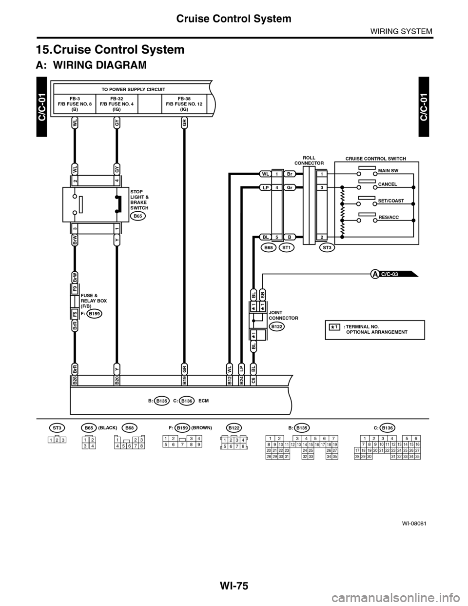
15.Cruise Control System
A: WIRING DIAGRAM
WI-08081
C/C-01C/C-01
B159F:
WLGY
WLGY
TO POWER SUPPLY CIRCUIT
FB-32F/B FUSE NO. 4(IG)
ECM
FB-3F/B FUSE NO. 8(B)
42
B65
BrW
BrW
BrR
3
Y
1
F9
F5
FUSE &RELAY BOX(F/B)B159F:
C/C-03A
BrR
B28
Y
B20
FB-38F/B FUSE NO. 12(IG)
GR
GR
B19B12B24
WL
B68
MAIN SW
CRUISE CONTROL SWITCH
CANCEL
SET/COAST
RES/ACC
WL1
4
BL5
(BROWN)B65B68F:
32187654
B159B122
B122
157628349
ST3
123
(BLACK)
Br
Gr
B
1
3
2
ST3ST1
ROLLCONNECTOR
STOPLIGHT &BRAKESWITCH
JOINTCONNECTOR
B135B:B136C:
LP
C6
BL
LP
1234
B: B135
5672134
29
101112131415252416
30
98171819202821222332312627333435
BL
BL
SB
*
**
: TERMINAL NO. OPTIONAL ARRANGEMENT*
C:B136
16101112131415252430
9871718192028212223293231
123456
2726333435
12345678
1
11
1
Page 2372 of 2453
WI-88
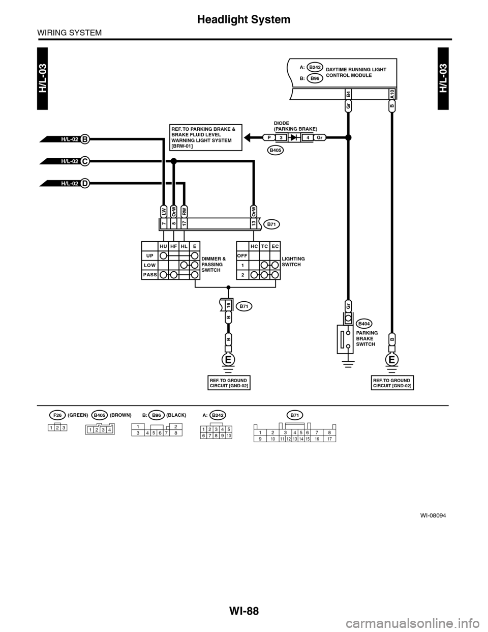
Headlight System
WIRING SYSTEM
WI-08094
H/L-03H/L-03
DAYTIME RUNNING LIGHTCONTROL MODULE
DIODE(PARKING BRAKE)
DIMMER &PA S S I N GSWITCH
LIGHTINGSWITCH
PA R K I N GBRAKESWITCH
B405
H/L-02D
H/L-02C
H/L-02B
817
B4
16
Gr
Gr
B71
23456718910 11 12 13 14 15 16 17
A10
B
B404
B71
B71
PGr34
B
B
7
LWOrWRW
13
OrW
REF. TO GROUNDCIRCUIT [GND-02]
B
REF. TO GROUNDCIRCUIT [GND-02]
UP
HU HF HL E
LOW
PASS
OFF
1
2
HC TC EC
B405F26
123
B96B:
B242A:
B242A:
12346789510
14723568
B96B:(BLACK)(BROWN)(GREEN)
REF. TO PARKING BRAKE &BRAKE FLUID LEVELWARNING LIGHT SYSTEM[BRW-01]
1234