2009 SUBARU TRIBECA Repair manual
[x] Cancel search: Repair manualPage 635 of 2453

SL-6
General Description
SECURITY AND LOCKS
5. KEYLESS ENTRY SYSTEM
B: CAUTION
•Before disassembling or reassembling parts, al-
ways disconnect the battery ground cable from bat-
tery. When repairing the audio, control module, etc.
which are provided with memory functions, record
the memory contents before disconnecting the
ground cable from battery. Otherwise, these con-
tents are erased upon disconnection.
•Reassemble the parts in the reverse order of dis-
assembly unless otherwise indicated.
•Adjust the parts to the specifications described in
this manual if so designated.
•Connect the connectors securely during reas-
sembly.
•After reassembly, ensure the functional parts op-
erate smoothly.
•The air bag system wiring harness is routed near
electrical parts and switches.
•Airbag system wiring harnesses and connectors
are yellow. Do not use the electrical test equipment
on these circuits.
•Be careful not to damage the airbag system wir-
ing harness when servicing the ignition key cylin-
der.
(1) Keyless entry control module (3) Door switch (5) Horn
(2) Rear gate latch switch (4) Body integrated unit (6) Keyless buzzer
SL-00440
(2)
(3)
(4)
(5)
(5)
(6)
(1)
Page 654 of 2453

SL-25
Keyless Entry System
SECURITY AND LOCKS
15.CHECK IGNITION SWITCH.
CAUTION:
When the ignition key lock is replaced, all ignition keys also must be registered. (Refer to the “IMMO-
BILIZER TEACHING OPERATION MANUAL”.)
Step Check Yes No
1CHECK FUSIBLE LINK.
Remove the fusible link main SBF and SBF-6
(in main fuse box), and visually check.
Is the fusible link blown out? Replace the fus-
ible link main SBF
or SBF-6. If the
replaced fusible
link has blown out
easily, repair the
short circuit
between the fus-
ible link and the
ignition switch.
Go to step 2.
2CHECK FOR POWER SUPPLY OF IGNITION
SWITCH.
1) Disconnect the ignition switch harness con-
nector.
2) Measure the voltage between harness con-
nector terminal and chassis ground.
Connector & terminal
(B72) No. 3 (+) — Chassis ground (– ):
Is the voltage more than 10 V? Go to step 3.Check the harness
for open circuits
and shorts
between the igni-
tion switch and
fusible link.
3CHECK IGNITION SWITCH.
1) Insert the ignition key into ignition switch,
and turn the each position.
2) Measure the resistance between ignition
switch terminals.
Connector & terminal
No. 3 — No. 4 (ACC position):
No. 3 — No. 4 — No. 6 — No. 1 (ON posi-
tion):
No. 3 — No. 6 — No. 1 — No. 2 (ST posi-
tion):
Is the resistance less than 1 Ω
when turning the ignition key to
each position?
Ignition switch is
normal.
Replace the igni-
tion switch with a
new part.
MENT, Ignition Key
Lock.>
Page 1183 of 2453
EN(H6DO)(diag)-22
General Scan Tool
ENGINE (DIAGNOSTICS)
8. General Scan Tool
A: OPERATION
1. HOW TO USE GENERAL SCAN TOOL
1) Prepare a scan tool (general scan tool) required
by SAE J1978.
2) Open the cover and connect the general scan
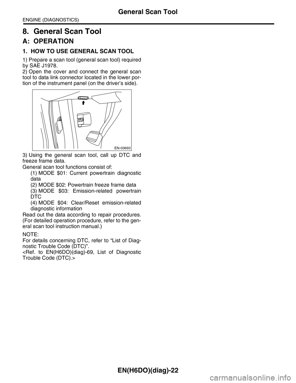
tool to data link connector located in the lower por-
tion of the instrument panel (on the driver’s side).
3) Using the general scan tool, call up DTC and
freeze frame data.
General scan tool functions consist of:
(1) MODE $01: Current powertrain diagnostic
data
(2) MODE $02: Powertrain freeze frame data
(3) MODE $03: Emission-related powertrain
DTC
(4) MODE $04: Clear/Reset emission-related
diagnostic information
Read out the data according to repair procedures.
(For detailed operation procedure, refer to the gen-
eral scan tool instruction manual.)
NOTE:
For details concerning DTC, refer to “List of Diag-
nostic Trouble Code (DTC)”.
EN-03693
Page 1238 of 2453
EN(H6DO)(diag)-77
Diagnostic Procedure with Diagnostic Trouble Code (DTC)
ENGINE (DIAGNOSTICS)
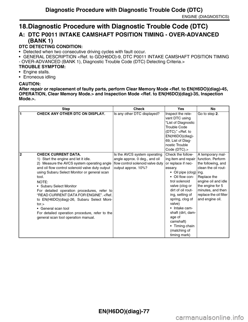
18.Diagnostic Procedure with Diagnostic Trouble Code (DTC)
A: DTC P0011 INTAKE CAMSHAFT POSITION TIMING - OVER-ADVANCED
(BANK 1)
DTC DETECTING CONDITION:
•Detected when two consecutive driving cycles with fault occur.
•GENERAL DESCRIPTION
TROUBLE SYMPTOM:
•Engine stalls.
•Erroneous idling
CAUTION:
After repair or replacement of faulty parts, perform Clear Memory Mode
Step Check Yes No
1CHECK ANY OTHER DTC ON DISPLAY.Is any other DTC displayed? Inspect the rele-
vant DTC using
“List of Diagnostic
Tr o u b l e C o d e
(DTC).”
69, List of Diag-
nostic Trouble
Code (DTC).>
Go to step 2.
2CHECK CURRENT DATA.
1) Start the engine and let it idle.
2) Measure the AVCS system operating angle
and oil flow control solenoid valve duty output
using Subaru Select Monitor or general scan
tool.
NOTE:•Subaru Select Monitor
For detailed operation procedures, refer to
“READ CURRENT DATA FOR ENGINE”.
tor.>
•General scan tool
For detailed operation procedure, refer to the
general scan tool operation manual.
Is the AVCS system operating
angle approx. 0 deg., and oil
flow control solenoid valve duty
output approx. 10%?
Check the follow-
ing item and repair
or replace if nec-
essary.
•Oil pipe (clog)
•Oil flow con-
trol solenoid
valve (clog or
dirt of oil rout-
ing, setting of
spring, clog of
valve)
•Intake cam-
shaft (dirt, dam-
age of
camshaft)
•Timing chain
(matching of
timing mark)
A temporary mal-
function. Perform
the following, and
clean the oil rout-
ing.
Replace the
engine oil and idle
the engine for 5
minutes, and then
replace the oil filter
and engine oil.
Page 1239 of 2453
EN(H6DO)(diag)-78
Diagnostic Procedure with Diagnostic Trouble Code (DTC)
ENGINE (DIAGNOSTICS)
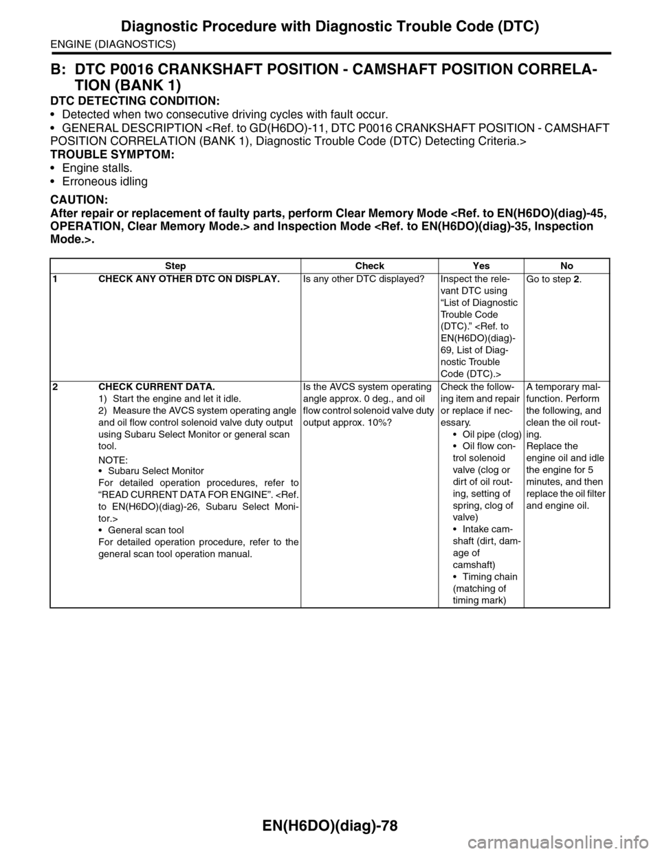
B: DTC P0016 CRANKSHAFT POSITION - CAMSHAFT POSITION CORRELA-
TION (BANK 1)
DTC DETECTING CONDITION:
•Detected when two consecutive driving cycles with fault occur.
•GENERAL DESCRIPTION
TROUBLE SYMPTOM:
•Engine stalls.
•Erroneous idling
CAUTION:
After repair or replacement of faulty parts, perform Clear Memory Mode
Step Check Yes No
1CHECK ANY OTHER DTC ON DISPLAY.Is any other DTC displayed? Inspect the rele-
vant DTC using
“List of Diagnostic
Tr o u b l e C o d e
(DTC).”
69, List of Diag-
nostic Trouble
Code (DTC).>
Go to step 2.
2CHECK CURRENT DATA.
1) Start the engine and let it idle.
2) Measure the AVCS system operating angle
and oil flow control solenoid valve duty output
using Subaru Select Monitor or general scan
tool.
NOTE:•Subaru Select Monitor
For detailed operation procedures, refer to
“READ CURRENT DATA FOR ENGINE”.
tor.>
•General scan tool
For detailed operation procedure, refer to the
general scan tool operation manual.
Is the AVCS system operating
angle approx. 0 deg., and oil
flow control solenoid valve duty
output approx. 10%?
Check the follow-
ing item and repair
or replace if nec-
essary.
•Oil pipe (clog)
•Oil flow con-
trol solenoid
valve (clog or
dirt of oil rout-
ing, setting of
spring, clog of
valve)
•Intake cam-
shaft (dirt, dam-
age of
camshaft)
•Timing chain
(matching of
timing mark)
A temporary mal-
function. Perform
the following, and
clean the oil rout-
ing.
Replace the
engine oil and idle
the engine for 5
minutes, and then
replace the oil filter
and engine oil.
Page 1240 of 2453
EN(H6DO)(diag)-79
Diagnostic Procedure with Diagnostic Trouble Code (DTC)
ENGINE (DIAGNOSTICS)
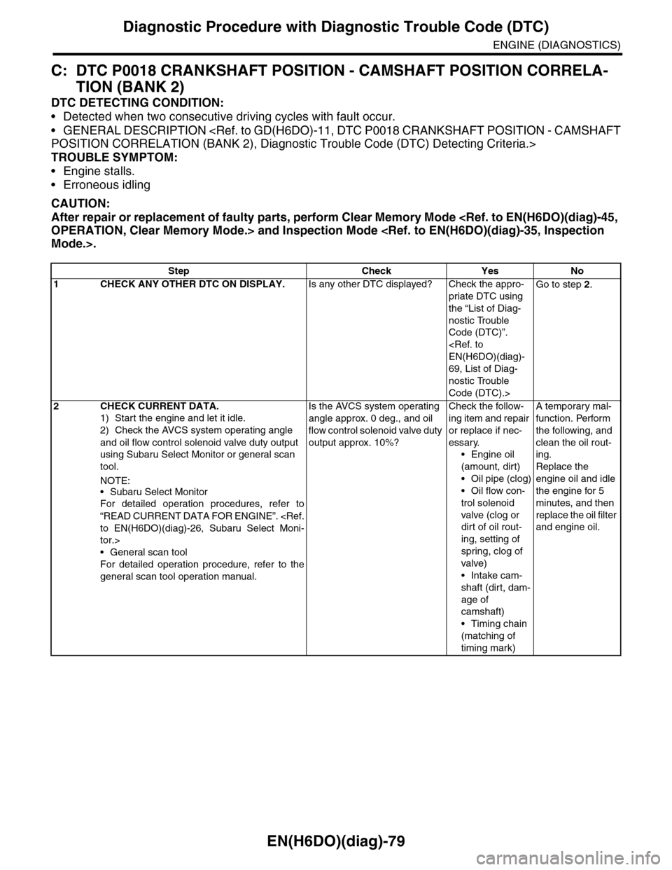
C: DTC P0018 CRANKSHAFT POSITION - CAMSHAFT POSITION CORRELA-
TION (BANK 2)
DTC DETECTING CONDITION:
•Detected when two consecutive driving cycles with fault occur.
•GENERAL DESCRIPTION
TROUBLE SYMPTOM:
•Engine stalls.
•Erroneous idling
CAUTION:
After repair or replacement of faulty parts, perform Clear Memory Mode
Step Check Yes No
1CHECK ANY OTHER DTC ON DISPLAY.Is any other DTC displayed? Check the appro-
priate DTC using
the “List of Diag-
nostic Trouble
Code (DTC)”.
69, List of Diag-
nostic Trouble
Code (DTC).>
Go to step 2.
2CHECK CURRENT DATA.
1) Start the engine and let it idle.
2) Check the AVCS system operating angle
and oil flow control solenoid valve duty output
using Subaru Select Monitor or general scan
tool.
NOTE:
•Subaru Select Monitor
For detailed operation procedures, refer to
“READ CURRENT DATA FOR ENGINE”.
tor.>
•General scan tool
For detailed operation procedure, refer to the
general scan tool operation manual.
Is the AVCS system operating
angle approx. 0 deg., and oil
flow control solenoid valve duty
output approx. 10%?
Check the follow-
ing item and repair
or replace if nec-
essary.
•Engine oil
(amount, dirt)
•Oil pipe (clog)
•Oil flow con-
trol solenoid
valve (clog or
dirt of oil rout-
ing, setting of
spring, clog of
valve)
•Intake cam-
shaft (dirt, dam-
age of
camshaft)
•Timing chain
(matching of
timing mark)
A temporary mal-
function. Perform
the following, and
clean the oil rout-
ing.
Replace the
engine oil and idle
the engine for 5
minutes, and then
replace the oil filter
and engine oil.
Page 1241 of 2453
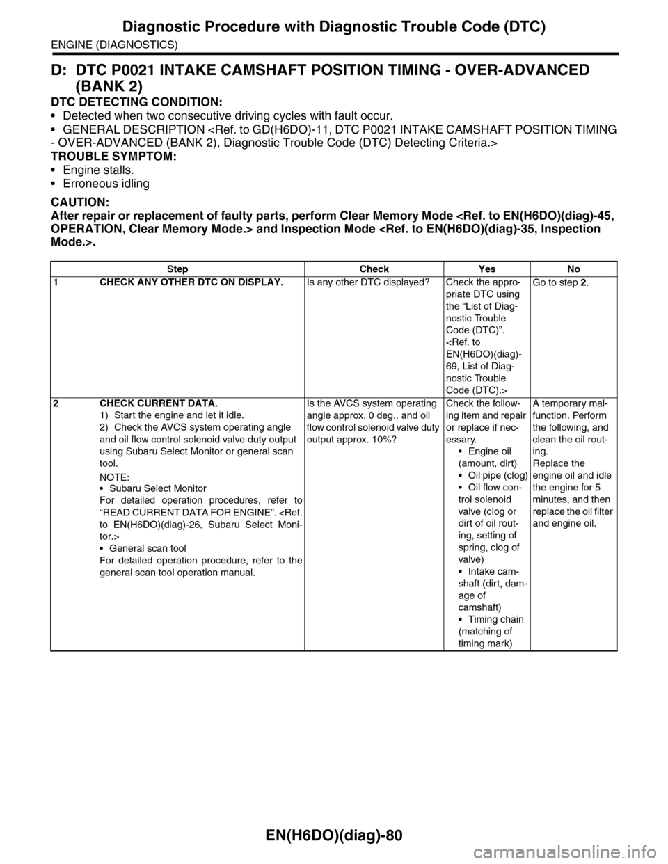
EN(H6DO)(diag)-80
Diagnostic Procedure with Diagnostic Trouble Code (DTC)
ENGINE (DIAGNOSTICS)
D: DTC P0021 INTAKE CAMSHAFT POSITION TIMING - OVER-ADVANCED
(BANK 2)
DTC DETECTING CONDITION:
•Detected when two consecutive driving cycles with fault occur.
•GENERAL DESCRIPTION
TROUBLE SYMPTOM:
•Engine stalls.
•Erroneous idling
CAUTION:
After repair or replacement of faulty parts, perform Clear Memory Mode
Step Check Yes No
1CHECK ANY OTHER DTC ON DISPLAY.Is any other DTC displayed? Check the appro-
priate DTC using
the “List of Diag-
nostic Trouble
Code (DTC)”.
69, List of Diag-
nostic Trouble
Code (DTC).>
Go to step 2.
2CHECK CURRENT DATA.
1) Start the engine and let it idle.
2) Check the AVCS system operating angle
and oil flow control solenoid valve duty output
using Subaru Select Monitor or general scan
tool.
NOTE:
•Subaru Select Monitor
For detailed operation procedures, refer to
“READ CURRENT DATA FOR ENGINE”.
tor.>
•General scan tool
For detailed operation procedure, refer to the
general scan tool operation manual.
Is the AVCS system operating
angle approx. 0 deg., and oil
flow control solenoid valve duty
output approx. 10%?
Check the follow-
ing item and repair
or replace if nec-
essary.
•Engine oil
(amount, dirt)
•Oil pipe (clog)
•Oil flow con-
trol solenoid
valve (clog or
dirt of oil rout-
ing, setting of
spring, clog of
valve)
•Intake cam-
shaft (dirt, dam-
age of
camshaft)
•Timing chain
(matching of
timing mark)
A temporary mal-
function. Perform
the following, and
clean the oil rout-
ing.
Replace the
engine oil and idle
the engine for 5
minutes, and then
replace the oil filter
and engine oil.
Page 1251 of 2453
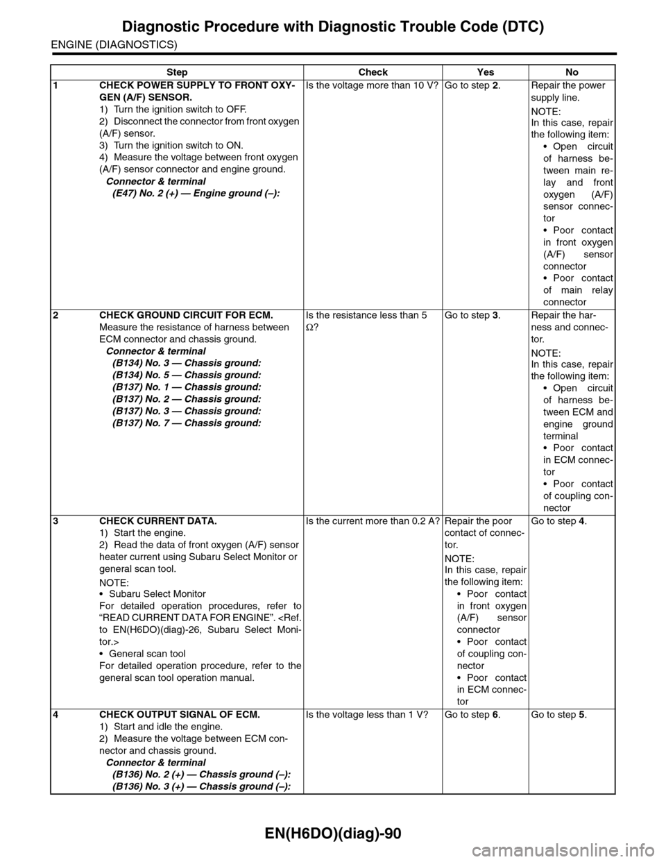
EN(H6DO)(diag)-90
Diagnostic Procedure with Diagnostic Trouble Code (DTC)
ENGINE (DIAGNOSTICS)
Step Check Yes No
1 CHECK POWER SUPPLY TO FRONT OXY-
GEN (A/F) SENSOR.
1) Turn the ignition switch to OFF.
2) Disconnect the connector from front oxygen
(A/F) sensor.
3) Turn the ignition switch to ON.
4) Measure the voltage between front oxygen
(A/F) sensor connector and engine ground.
Connector & terminal
(E47) No. 2 (+) — Engine ground (–):
Is the voltage more than 10 V? Go to step 2.Repair the power
supply line.
NOTE:
In this case, repair
the following item:
•Open circuit
of harness be-
tween main re-
lay and front
oxygen (A/F)
sensor connec-
tor
•Poor contact
in front oxygen
(A/F) sensor
connector
•Poor contact
of main relay
connector
2CHECK GROUND CIRCUIT FOR ECM.
Measure the resistance of harness between
ECM connector and chassis ground.
Connector & terminal
(B134) No. 3 — Chassis ground:
(B134) No. 5 — Chassis ground:
(B137) No. 1 — Chassis ground:
(B137) No. 2 — Chassis ground:
(B137) No. 3 — Chassis ground:
(B137) No. 7 — Chassis ground:
Is the resistance less than 5
Ω?
Go to step 3.Repair the har-
ness and connec-
tor.
NOTE:
In this case, repair
the following item:
•Open circuit
of harness be-
tween ECM and
engine ground
terminal
•Poor contact
in ECM connec-
tor
•Poor contact
of coupling con-
nector
3CHECK CURRENT DATA.
1) Start the engine.
2) Read the data of front oxygen (A/F) sensor
heater current using Subaru Select Monitor or
general scan tool.
NOTE:•Subaru Select Monitor
For detailed operation procedures, refer to
“READ CURRENT DATA FOR ENGINE”.
tor.>
•General scan tool
For detailed operation procedure, refer to the
general scan tool operation manual.
Is the current more than 0.2 A? Repair the poor
contact of connec-
tor.
NOTE:
In this case, repair
the following item:
•Poor contact
in front oxygen
(A/F) sensor
connector
•Poor contact
of coupling con-
nector
•Poor contact
in ECM connec-
tor
Go to step 4.
4CHECK OUTPUT SIGNAL OF ECM.
1) Start and idle the engine.
2) Measure the voltage between ECM con-
nector and chassis ground.
Connector & terminal
(B136) No. 2 (+) — Chassis ground (–):
(B136) No. 3 (+) — Chassis ground (–):
Is the voltage less than 1 V? Go to step 6.Go to step 5.