2009 SUBARU TRIBECA Misfire
[x] Cancel search: MisfirePage 1405 of 2453
EN(H6DO)(diag)-244
Diagnostic Procedure with Diagnostic Trouble Code (DTC)
ENGINE (DIAGNOSTICS)
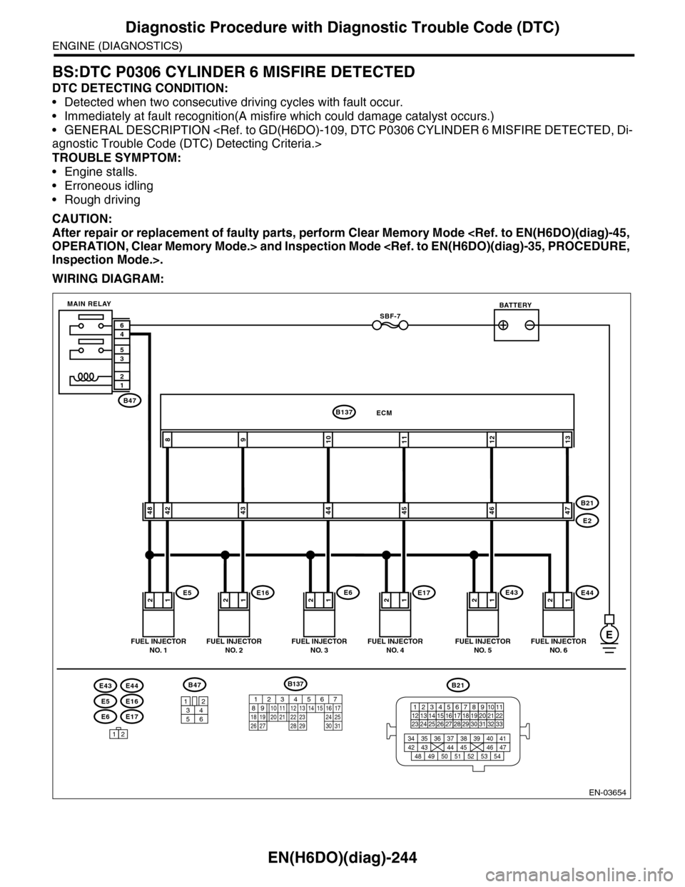
BS:DTC P0306 CYLINDER 6 MISFIRE DETECTED
DTC DETECTING CONDITION:
•Detected when two consecutive driving cycles with fault occur.
•Immediately at fault recognition(A misfire which could damage catalyst occurs.)
•GENERAL DESCRIPTION
TROUBLE SYMPTOM:
•Engine stalls.
•Erroneous idling
•Rough driving
CAUTION:
After repair or replacement of faulty parts, perform Clear Memory Mode
WIRING DIAGRAM:
EN-03654
E6E17
E5E16
E43E44
12121212
109811
4248434445
ECMB137
E5E16E6E17
B21
E2
FUEL INJECTORNO. 1FUEL INJECTORNO. 2FUEL INJECTORNO. 3FUEL INJECTORNO. 4
BATTERY
1212
1213
4647
E43E44
FUEL INJECTORNO. 5FUEL INJECTORNO. 6
SBF-7
B47
MAIN RELAY
12
35
46
B47
3412
56
12
B21
123412131415567816171819910 1120212223 24 25 2627 28 29 3031 32 33
3534 37363938 41404342 4445 47464948 51505352 54
E
B137
85610 11 12 13 14 157213416
3019 20 2228 29
91718 2521 23 243126 27
Page 1408 of 2453
EN(H6DO)(diag)-247
Diagnostic Procedure with Diagnostic Trouble Code (DTC)
ENGINE (DIAGNOSTICS)
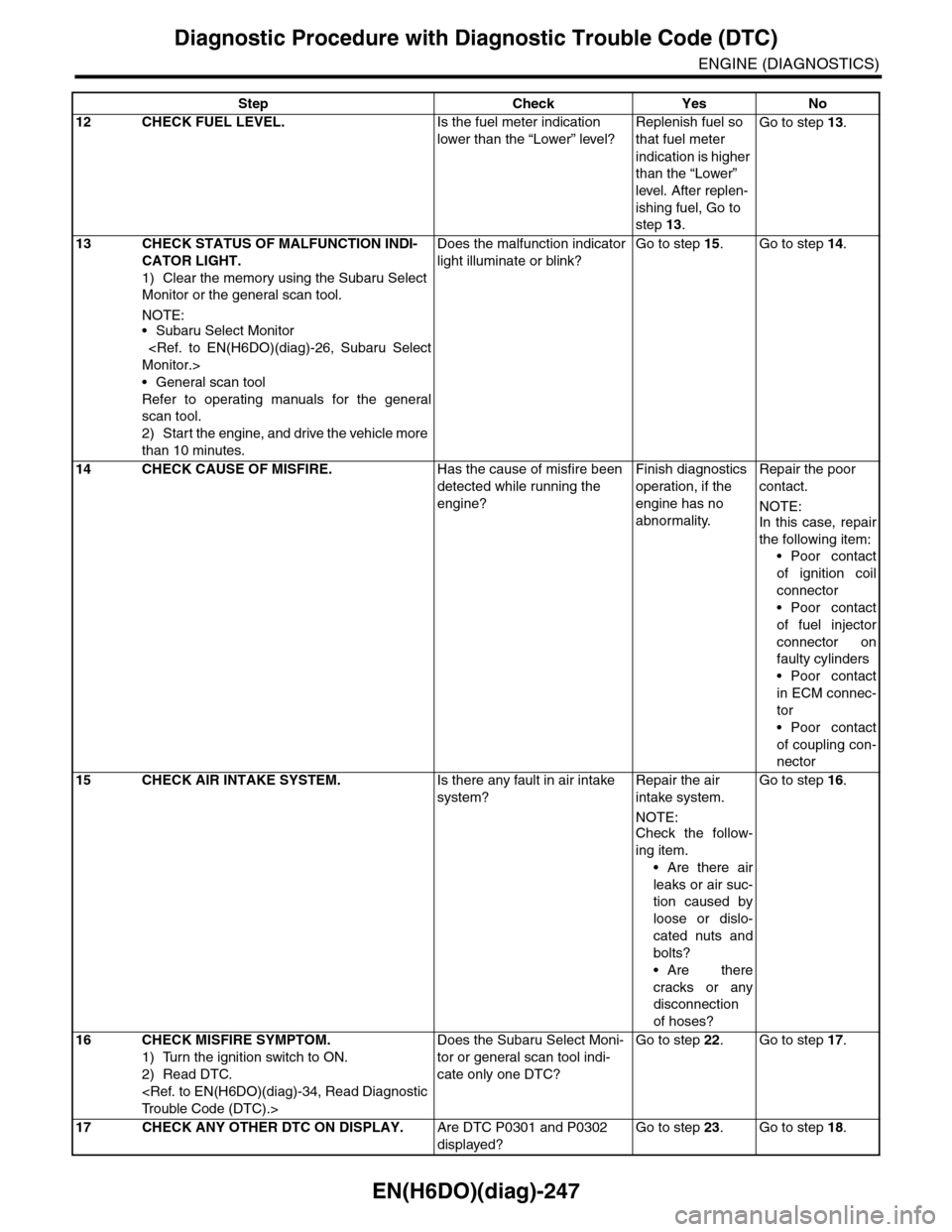
12 CHECK FUEL LEVEL.Is the fuel meter indication
lower than the “Lower” level?
Replenish fuel so
that fuel meter
indication is higher
than the “Lower”
level. After replen-
ishing fuel, Go to
step 13.
Go to step 13.
13 CHECK STATUS OF MALFUNCTION INDI-
CATOR LIGHT.
1) Clear the memory using the Subaru Select
Monitor or the general scan tool.
NOTE:•Subaru Select Monitor
•General scan tool
Refer to operating manuals for the general
scan tool.
2) Start the engine, and drive the vehicle more
than 10 minutes.
Does the malfunction indicator
light illuminate or blink?
Go to step 15.Go to step 14.
14 CHECK CAUSE OF MISFIRE.Has the cause of misfire been
detected while running the
engine?
Finish diagnostics
operation, if the
engine has no
abnormality.
Repair the poor
contact.
NOTE:In this case, repair
the following item:
•Poor contact
of ignition coil
connector
•Poor contact
of fuel injector
connector on
faulty cylinders
•Poor contact
in ECM connec-
tor
•Poor contact
of coupling con-
nector
15 CHECK AIR INTAKE SYSTEM.Is there any fault in air intake
system?
Repair the air
intake system.
NOTE:
Check the follow-
ing item.
•Are there air
leaks or air suc-
tion caused by
loose or dislo-
cated nuts and
bolts?
•Are there
cracks or any
disconnection
of hoses?
Go to step 16.
16 CHECK MISFIRE SYMPTOM.
1) Turn the ignition switch to ON.
2) Read DTC.
Does the Subaru Select Moni-
tor or general scan tool indi-
cate only one DTC?
Go to step 22.Go to step 17.
17 CHECK ANY OTHER DTC ON DISPLAY.Are DTC P0301 and P0302
displayed?
Go to step 23.Go to step 18.
Step Check Yes No
Page 1617 of 2453
GD(H6DO)-5
List of Diagnostic Trouble Code (DTC)
GENERAL DESCRIPTION
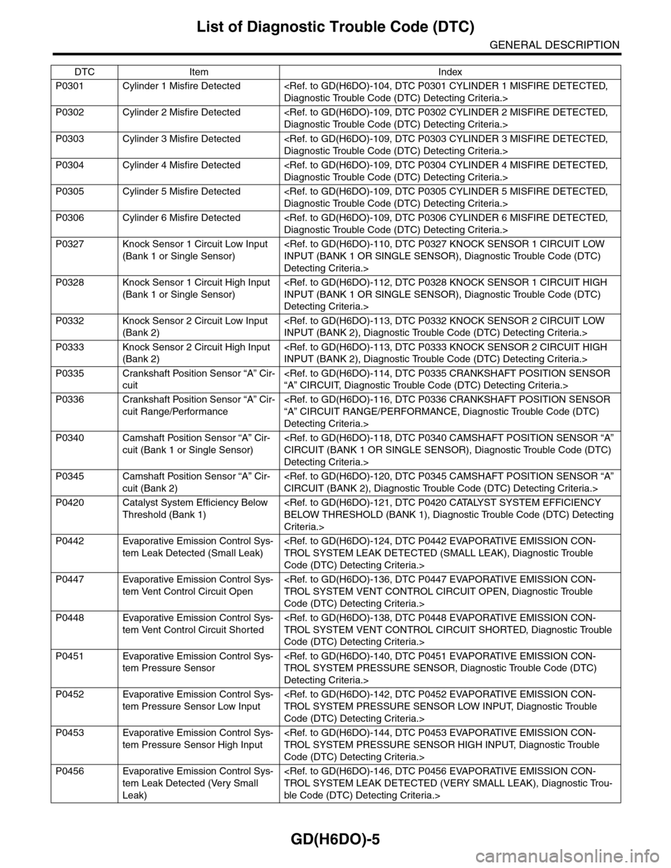
P0301 Cylinder 1 Misfire Detected
P0302 Cylinder 2 Misfire Detected
P0303 Cylinder 3 Misfire Detected
P0304 Cylinder 4 Misfire Detected
P0305 Cylinder 5 Misfire Detected
P0306 Cylinder 6 Misfire Detected
P0327 Knock Sensor 1 Circuit Low Input
(Bank 1 or Single Sensor)
Detecting Criteria.>
P0328 Knock Sensor 1 Circuit High Input
(Bank 1 or Single Sensor)
Detecting Criteria.>
P0332 Knock Sensor 2 Circuit Low Input
(Bank 2)
P0333 Knock Sensor 2 Circuit High Input
(Bank 2)
P0335 Crankshaft Position Sensor “A” Cir-
cuit
P0336 Crankshaft Position Sensor “A” Cir-
cuit Range/Performance
Detecting Criteria.>
P0340 Camshaft Position Sensor “A” Cir-
cuit (Bank 1 or Single Sensor)
Detecting Criteria.>
P0345 Camshaft Position Sensor “A” Cir-
cuit (Bank 2)
P0420 Catalyst System Efficiency Below
Threshold (Bank 1)
Criteria.>
P0442 Evaporative Emission Control Sys-
tem Leak Detected (Small Leak)
Code (DTC) Detecting Criteria.>
P0447 Evaporative Emission Control Sys-
tem Vent Control Circuit Open
Code (DTC) Detecting Criteria.>
P0448 Evaporative Emission Control Sys-
tem Vent Control Circuit Shorted
Code (DTC) Detecting Criteria.>
P0451 Evaporative Emission Control Sys-
tem Pressure Sensor
Detecting Criteria.>
P0452 Evaporative Emission Control Sys-
tem Pressure Sensor Low Input
Code (DTC) Detecting Criteria.>
P0453 Evaporative Emission Control Sys-
tem Pressure Sensor High Input
Code (DTC) Detecting Criteria.>
P0456 Evaporative Emission Control Sys-
tem Leak Detected (Very Small
Leak)
ble Code (DTC) Detecting Criteria.>
DTC Item Index
Page 1684 of 2453
GD(H6DO)-72
Diagnostic Trouble Code (DTC) Detecting Criteria
GENERAL DESCRIPTION
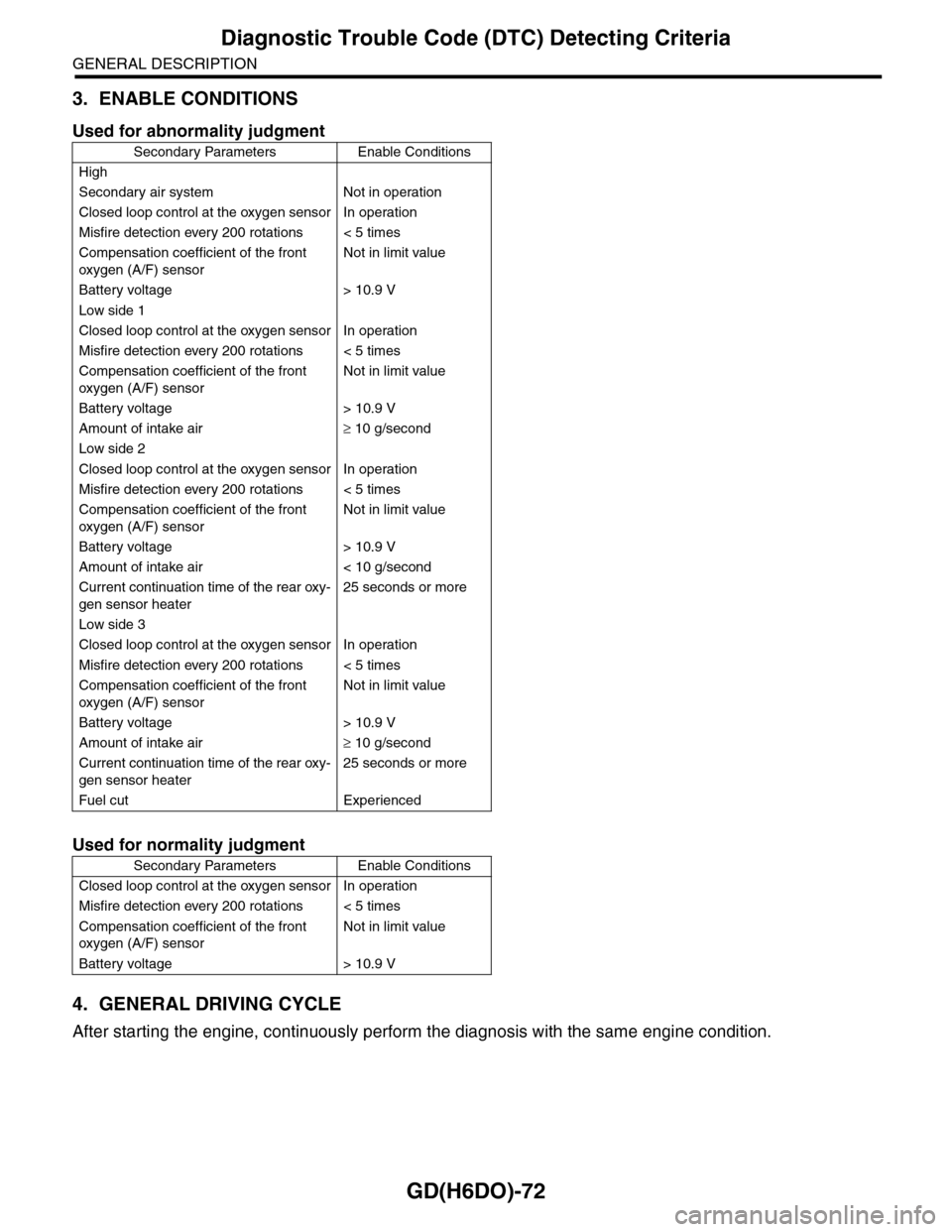
3. ENABLE CONDITIONS
4. GENERAL DRIVING CYCLE
After starting the engine, continuously perform the diagnosis with the same engine condition.
Used for abnormality judgment
Secondary Parameters Enable Conditions
High
Secondary air system Not in operation
Closed loop control at the oxygen sensor In operation
Misfire detection every 200 rotations < 5 times
Compensation coefficient of the front
oxygen (A/F) sensor
Not in limit value
Battery voltage > 10.9 V
Low side 1
Closed loop control at the oxygen sensor In operation
Misfire detection every 200 rotations < 5 times
Compensation coefficient of the front
oxygen (A/F) sensor
Not in limit value
Battery voltage > 10.9 V
Amount of intake air≥ 10 g/second
Low side 2
Closed loop control at the oxygen sensor In operation
Misfire detection every 200 rotations < 5 times
Compensation coefficient of the front
oxygen (A/F) sensor
Not in limit value
Battery voltage > 10.9 V
Amount of intake air < 10 g/second
Current continuation time of the rear oxy-
gen sensor heater
25 seconds or more
Low side 3
Closed loop control at the oxygen sensor In operation
Misfire detection every 200 rotations < 5 times
Compensation coefficient of the front
oxygen (A/F) sensor
Not in limit value
Battery voltage > 10.9 V
Amount of intake air≥ 10 g/second
Current continuation time of the rear oxy-
gen sensor heater
25 seconds or more
Fuel cut Experienced
Used for normality judgment
Secondary Parameters Enable Conditions
Closed loop control at the oxygen sensor In operation
Misfire detection every 200 rotations < 5 times
Compensation coefficient of the front
oxygen (A/F) sensor
Not in limit value
Battery voltage > 10.9 V
Page 1692 of 2453
GD(H6DO)-80
Diagnostic Trouble Code (DTC) Detecting Criteria
GENERAL DESCRIPTION
AR:DTC P0140 O2 SENSOR CIRCUIT NO ACTIVITY DETECTED (BANK 1 SEN-
SOR 2)
1. OUTLINE OF DIAGNOSIS
Detect the rear oxygen sensor open or short circuit. Judge as NG when the rear oxygen sensor voltage can
be determined to be abnormal considering conditions such as intake air amount, engine coolant tempera-
ture, main feedback control and deceleration fuel cut.
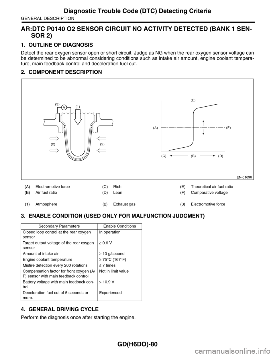
2. COMPONENT DESCRIPTION
3. ENABLE CONDITION (USED ONLY FOR MALFUNCTION JUDGMENT)
4. GENERAL DRIVING CYCLE
Perform the diagnosis once after starting the engine.
(A) Electromotive force (C) Rich (E) Theoretical air fuel ratio
(B) Air fuel ratio (D) Lean (F) Comparative voltage
(1) Atmosphere (2) Exhaust gas (3) Electromotive force
Secondary Parameters Enable Conditions
Closed loop control at the rear oxygen
sensor
In operation
Ta r g e t o u t p u t v o l t a g e o f t h e r e a r o x y g e n
sensor
≥ 0.6 V
Amount of intake air≥ 10 g/second
Engine coolant temperature≥ 75°C (167°F)
Misfire detection every 200 rotations≤ 7 times
Compensation factor for front oxygen (A/
F) sensor with main feedback control
Not in limit value
Battery voltage with main feedback con-
trol
> 10.9 V
Deceleration fuel cut of 5 seconds or
more.
Experienced
EN-01696
(3)V(1)
(2) (2)
(E)
(F)
(C) (B) (D)
(A)
Page 1716 of 2453
GD(H6DO)-104
Diagnostic Trouble Code (DTC) Detecting Criteria
GENERAL DESCRIPTION
BN:DTC P0301 CYLINDER 1 MISFIRE DETECTED
1. OUTLINE OF DIAGNOSIS
Detect the presence of misfire occurrence. (Revolution fluctuation method)
Monitoring Misfire which influences exhaust deterioration (1.5 times of FTP) and catalyst damage is made
obligatory by the law. Misfire affecting these two has three patterns below. Intermittent misfire (Different cyl-
inders misfire intermittently.):
•Intermittent misfire (The same cylinder misfires in random, or different cylinders misfire in random.): FTP
1.5 times misfire
•Every time misfire (The same cylinder misfires every time.): FTP 1.5 times misfire, Catalyst damage misfire
The following detecting methods are adopted for these detection.
1) Intermittent misfire: FTP 1.5 times misfire
•120° Interval Difference Method
•360° Interval Difference Method (whole range)
•720° Interval Difference Method (3,000 rpm or less)
2) Misfire every time: FTP 1.5 times misfire, Catalyst damage misfire
•360° Interval Difference Method
2. ENABLE CONDITIONS
Map 3
3. GENERAL DRIVING CYCLE
•If conditions are met, detect misfire from idling to high rotation.
•Perform the diagnosis continuously.
Secondary Parameters Enable Conditions
All secondary parameters enable condi-
tions
1 second or more
120° Intake manifold pressure change at
CA
< 20 kPa (150 mmHg,
5.9 inHg)
Throttle position change during 16 milli-
seconds
< 20°
Fuel shut-off function Not in operation
Fuel level≥ 9.6 2 (2.54 US gal,
2.11 Imp gal)
Ve h i c l e d y n a m i c c o n t r o l o r AT t o r q u e
control
Not in operation
Evaporative system leak check Not in operation
Engine speed 400 — 8000 rpm
Intake manifold pressure >Value of Map 3 or
more
Battery voltage≥ 8 V
Atmospheric pressure≥ 75.0 kPa (563
mmHg, 22.17 inHg)
Fuel parameter determination Not extremely low vol-
atility
rpm 700 1000 1500 2000 2500 3000 3500 4000 4500 5000 5500 6000 6500 7000
kPa
(mmHg,
inHg)
26.7
(200.0,
7.87)
26.7
(200.0,
7.87)
24.0
(180.0,
7.09)
24.1
(181.0,
7.13)
24.3
(182.0,
7.17)
24.7
(185.0,
7.28)
28.3
(212.3,
8.36)
30.9
(232.1,
9.14)
32.9
(247.0,
9.72)
33.1
(248.0,
9.76)
34.3
(257.0,
10.12)
38.1
(286.0,
11.26)
41.9
(314.0,
12.36)
48.9
(367.0,
14.45)
Page 1717 of 2453
GD(H6DO)-105
Diagnostic Trouble Code (DTC) Detecting Criteria
GENERAL DESCRIPTION
4. DIAGNOSTIC METHOD
When a misfire occurs, the engine RPM will decreased and the crankshaft position speed will change. Cal-
culate the interval difference value (diagnostic value) from crankshaft position speed by the following formu-
la, and judge whether a misfire is occurring or not comparing the calculated result with judgment value.
Counting the number of misfires, if the misfire ratio is higher during 1000 rev. or 200 rev. Judge correspond-
ing cylinders as NG.
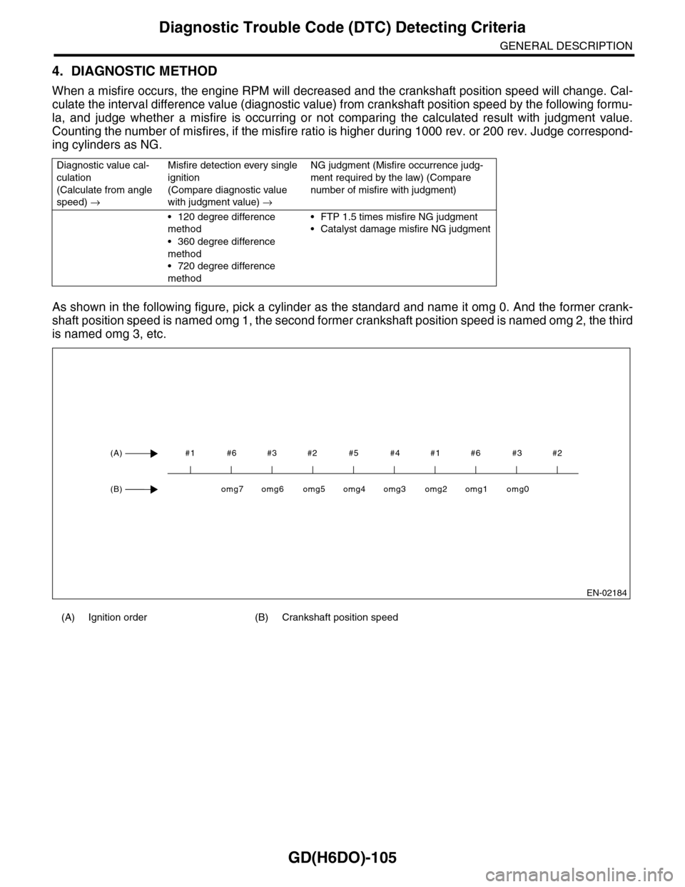
As shown in the following figure, pick a cylinder as the standard and name it omg 0. And the former crank-
shaft position speed is named omg 1, the second former crankshaft position speed is named omg 2, the third
is named omg 3, etc.
Diagnostic value cal-
culation
(Calculate from angle
speed) →
Misfire detection every single
ignition
(Compare diagnostic value
with judgment value) →
NG judgment (Misfire occurrence judg-
ment required by the law) (Compare
number of misfire with judgment)
•120 degree difference
method
•360 degree difference
method
•720 degree difference
method
•FTP 1.5 times misfire NG judgment
•Catalyst damage misfire NG judgment
(A) Ignition order (B) Crankshaft position speed
EN-02184
#1 #6 #3 #2 #5 #4 #1 #6 #3 #2(A)
(B)omg0omg1omg2omg3omg4omg5omg6omg7
Page 1718 of 2453
GD(H6DO)-106
Diagnostic Trouble Code (DTC) Detecting Criteria
GENERAL DESCRIPTION
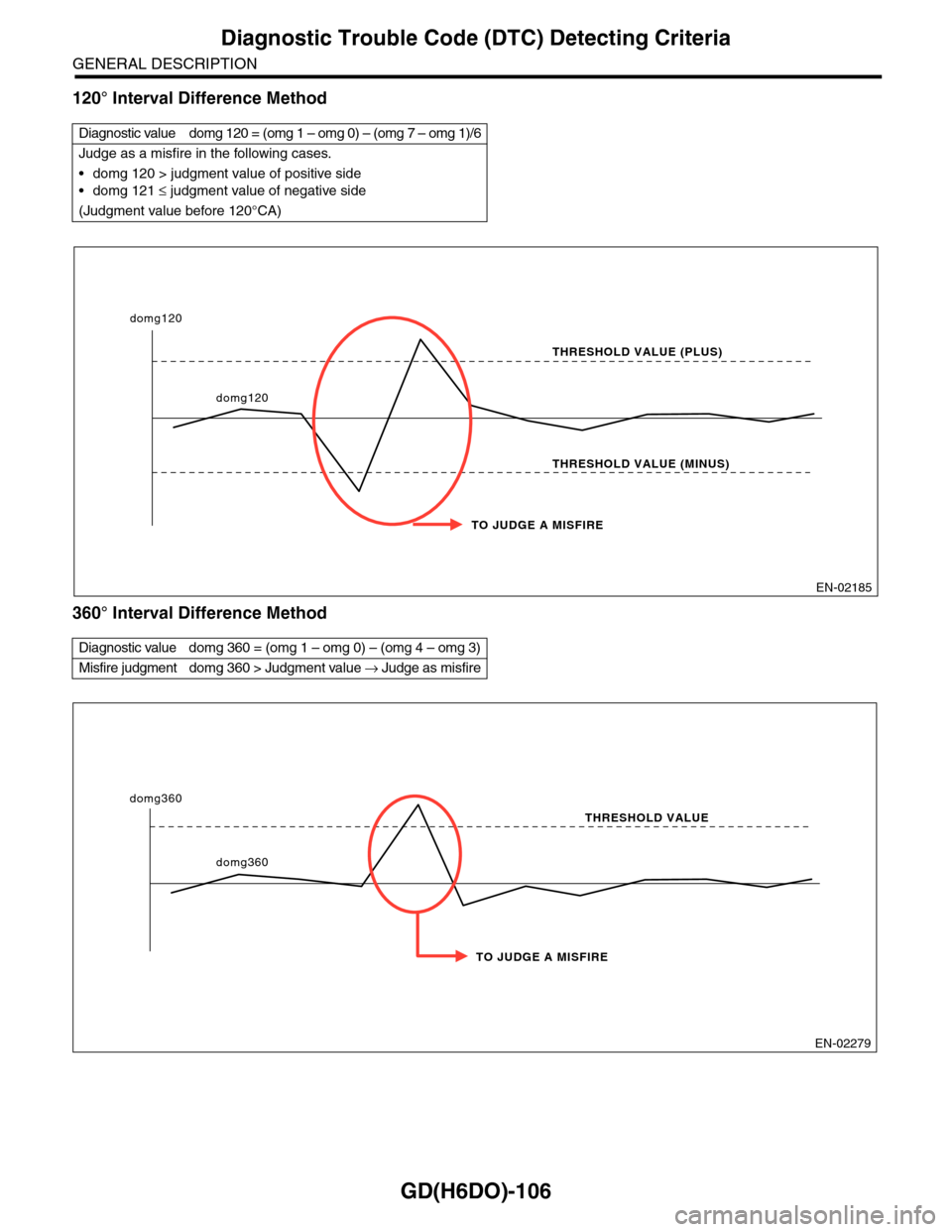
120° Interval Difference Method
360° Interval Difference Method
Diagnostic value domg 120 = (omg 1 – omg 0) – (omg 7 – omg 1)/6
Judge as a misfire in the following cases.
•domg 120 > judgment value of positive side
•domg 121 ≤ judgment value of negative side
(Judgment value before 120°CA)
Diagnostic value domg 360 = (omg 1 – omg 0) – (omg 4 – omg 3)
Misfire judgment domg 360 > Judgment value → Judge as misfire
EN-02185
TO JUDGE A MISFIRE
THRESHOLD VALUE (PLUS)
THRESHOLD VALUE (MINUS)
domg120
domg120
EN-02279
TO JUDGE A MISFIRE
THRESHOLD VALUE
domg360
domg360