Page 1773 of 2453
GD(H6DO)-161
Diagnostic Trouble Code (DTC) Detecting Criteria
GENERAL DESCRIPTION
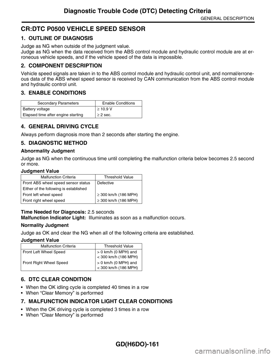
CR:DTC P0500 VEHICLE SPEED SENSOR
1. OUTLINE OF DIAGNOSIS
Judge as NG when outside of the judgment value.
Judge as NG when the data received from the ABS control module and hydraulic control module are at er-
roneous vehicle speeds, and if the vehicle speed of the data is impossible.
2. COMPONENT DESCRIPTION
Vehicle speed signals are taken in to the ABS control module and hydraulic control unit, and normal/errone-
ous data of the ABS wheel speed sensor is received by CAN communication from the ABS control module
and hydraulic control unit.
3. ENABLE CONDITIONS
4. GENERAL DRIVING CYCLE
Always perform diagnosis more than 2 seconds after starting the engine.
5. DIAGNOSTIC METHOD
Abnormality Judgment
Judge as NG when the continuous time until completing the malfunction criteria below becomes 2.5 second
or more.
Time Needed for Diagnosis: 2.5 seconds
Malfunction Indicator Light: Illuminates as soon as a malfunction occurs.
Normality Judgment
Judge as OK and clear the NG when all of the following criteria are established.
6. DTC CLEAR CONDITION
•When the OK idling cycle is completed 40 times in a row
•When “Clear Memory” is performed
7. MALFUNCTION INDICATOR LIGHT CLEAR CONDITIONS
•When the OK driving cycle is completed 3 times in a row
•When “Clear Memory” is performed
Secondary Parameters Enable Conditions
Battery voltage≥ 10.9 V
Elapsed time after engine starting≥ 2 sec.
Judgment Value
Malfunction Criteria Threshold Value
Fr o nt A B S w he e l s pe ed se n so r st at u s D efe ct i ve
Either of the following is established
Fr o nt l ef t whe e l s pe e d≥ 300 km/h (186 MPH)
Fr o nt r i gh t whe e l sp e ed≥ 300 km/h (186 MPH)
Judgment Value
Malfunction Criteria Threshold Value
Fr o nt L ef t Wh e el S pe e d > 0 km /h ( 0 M P H) a n d
< 300 km/h (186 MPH)
Fr o nt Ri gh t Wh e el S pe e d > 0 km /h ( 0 M P H) a n d
< 300 km/h (186 MPH)
Page 1774 of 2453
GD(H6DO)-162
Diagnostic Trouble Code (DTC) Detecting Criteria
GENERAL DESCRIPTION
8. FAIL SAFE
•ABS wheel speed sensor signal process: Vehicle speed = 10 km/h (6 MPH)
•ISC control: ISC feedback amount calculation prohibited
•Radiator fan control: Send the duty signal 50% to the controller.
9. ECM OPERATION AT DTC SETTING
Memorize the freeze frame data. (For test mode $02)
Page 1961 of 2453
SC(H6DO)-3
General Description
STARTING/CHARGING SYSTEMS
B: COMPONENT
1. STARTER
(1) Front bracket (12) Wave washer (23) Space ring
(2) Front bearing (13) Internal gear (24) Snap ring
(3) Plunger (14) Washer (25) End frame cover
(4) Snap ring (15) Shaft (26) Plunger spring
(5) Stopper (16) Planetary gear (27) Magnet switch
(6) Overrunning clutch (17) Armature plate
(7) Snap ring (18) YokeTightening torque: N·m (kgf-m, ft-lb)
(8) Washer (19) ArmatureT1: 1.4 (0.14, 1.03)
(9) Lever (20) Brush holder ASSYT2: 6 (0.6, 4.4)
(10) Oilless bearing (21) End frameT3: 7.5 (0.8, 5.5)
(11) Shock absorber bearing (22) Rear bearingT4: 10 (1.0, 7.4)
SC-02108
T3
T1
T2
(1)
(2)
T4
(4)(21)
(22)
(23)
(24)
(25)(5)(6)
(7)
(8)
(15)
(14)(13)
(12)(11)
(10)(9)
(3)
(26)
(27)
(16)(17)
(18)
(19)
(20)
Page 1966 of 2453
SC(H6DO)-8
Starter
STARTING/CHARGING SYSTEMS
14) Remove the shaft assembly, overrunning
clutch and lever from front bracket as a unit.
15) Remove the overrunning clutch from shaft as-
sembly as follows:
(1) Remove the stopper from snap ring by light-
ly tapping the stopper with an appropriate tool
(such as a fit socket wrench).
(2) Remove the snap ring, stopper and clutch
from shaft.
16) Remove the snap ring.
17) Remove the shock absorber bearing, wave
washer and internal gear from shaft.
18) Remove the front bearing from front bracket.
(1) Set an appropriate tool (φ13 mm) to front
bearing.
(2) Using a press, remove the front bearing.
(A) Front bracket
(B) Lever
(C) Shaft ASSY
(A) Socket wrench
(B) Snap ring
(C) Shaft
(D) Stopper
SC-02052
(B)
(A)
(C)
SC-00014
(A)
(B)
(C)(D)
(A) Shock absorber bearing
(B) Wave washer
(C) Internal gear
SC-02053
SC-02054
(C)
(A)
(B)
SC-02055
Page 1967 of 2453
SC(H6DO)-9
Starter
STARTING/CHARGING SYSTEMS
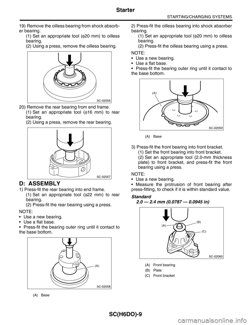
19) Remove the oilless bearing from shock absorb-
er bearing.
(1) Set an appropriate tool (φ20 mm) to oilless
bearing.
(2) Using a press, remove the oilless bearing.
20) Remove the rear bearing from end frame.
(1) Set an appropriate tool (φ16 mm) to rear
bearing.
(2) Using a press, remove the rear bearing.
D: ASSEMBLY
1) Press-fit the rear bearing into end frame.
(1) Set an appropriate tool (φ22 mm) to rear
bearing.
(2) Press-fit the rear bearing using a press.
NOTE:
•Use a new bearing.
•Use a flat base.
•Press-fit the bearing outer ring until it contact to
the base bottom.
2) Press-fit the oilless bearing into shock absorber
bearing.
(1) Set an appropriate tool (φ20 mm) to oilless
bearing.
(2) Press-fit the oilless bearing using a press.
NOTE:
•Use a new bearing.
•Use a flat base.
•Press-fit the bearing outer ring until it contact to
the base bottom.
3) Press-fit the front bearing into front bracket.
(1) Set the front bearing into front bracket.
(2) Set an appropriate tool (2.0-mm thickness
plate) to front bracket, and press-fit the front
bearing using a press.
NOTE:
•Use a new bearing.
•Measure the protrusion of front bearing after
press-fitting, to check if it is within standard value.
Standard
2.0 — 2.4 mm (0.0787 — 0.0945 in)
(A) Base
SC-02056
SC-02057
SC-02058
(A)
(A) Base
(A) Front bearing
(B) Plate
(C) Front bracket
SC-02059
(A)
SC-02060
(B)
(C)
(A)
Page 1968 of 2453
SC(H6DO)-10
Starter
STARTING/CHARGING SYSTEMS
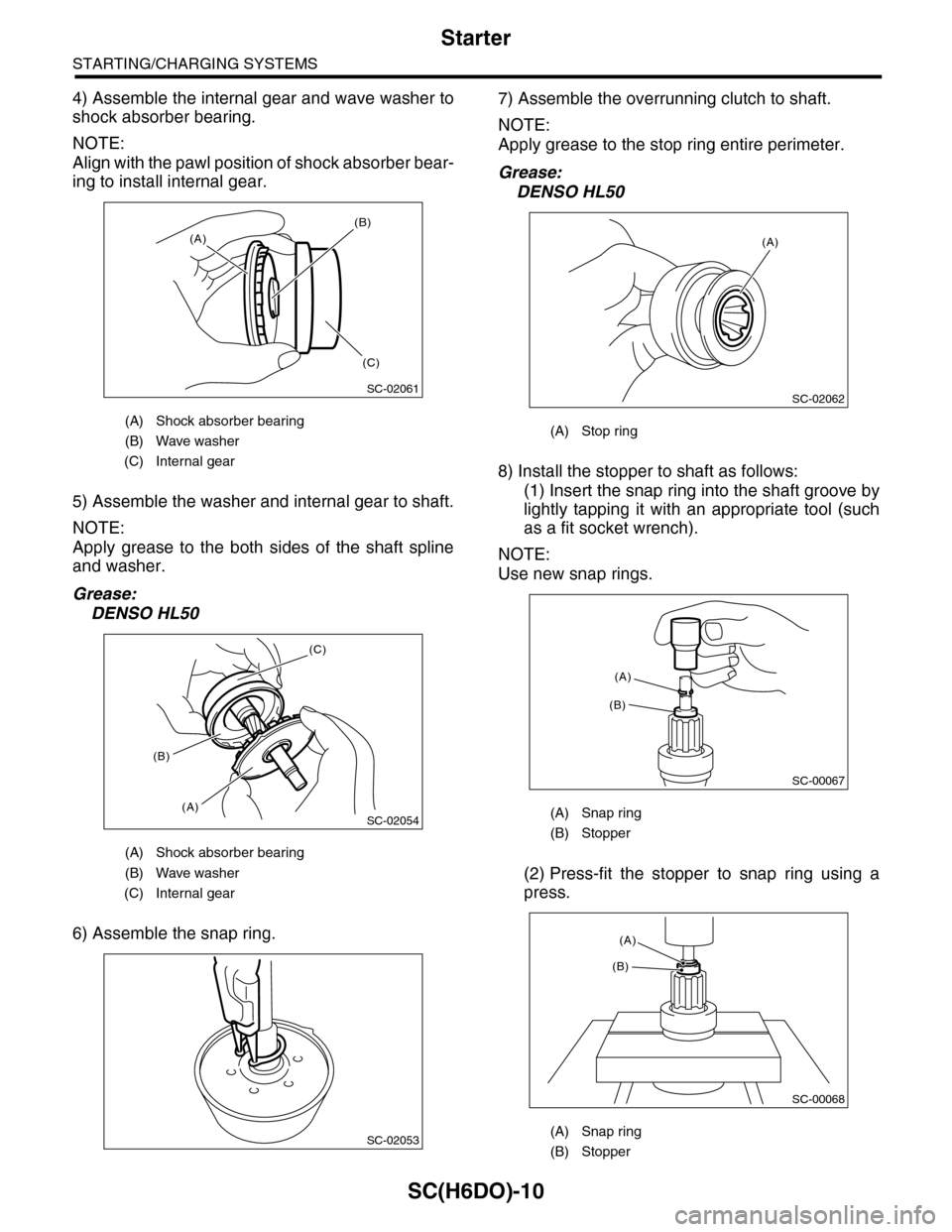
4) Assemble the internal gear and wave washer to
shock absorber bearing.
NOTE:
Align with the pawl position of shock absorber bear-
ing to install internal gear.
5) Assemble the washer and internal gear to shaft.
NOTE:
Apply grease to the both sides of the shaft spline
and washer.
Grease:
DENSO HL50
6) Assemble the snap ring.
7) Assemble the overrunning clutch to shaft.
NOTE:
Apply grease to the stop ring entire perimeter.
Grease:
DENSO HL50
8) Install the stopper to shaft as follows:
(1) Insert the snap ring into the shaft groove by
lightly tapping it with an appropriate tool (such
as a fit socket wrench).
NOTE:
Use new snap rings.
(2) Press-fit the stopper to snap ring using a
press.
(A) Shock absorber bearing
(B) Wave washer
(C) Internal gear
(A) Shock absorber bearing
(B) Wave washer
(C) Internal gear
SC-02061
(A)
(B)
(C)
SC-02054
(C)
(A)
(B)
SC-02053
(A) Stop ring
(A) Snap ring
(B) Stopper
(A) Snap ring
(B) Stopper
SC-02062
(A)
SC-00067
(B)
(A)
SC-00068
(A)
(B)
Page 1975 of 2453
SC(H6DO)-17
Starter
STARTING/CHARGING SYSTEMS
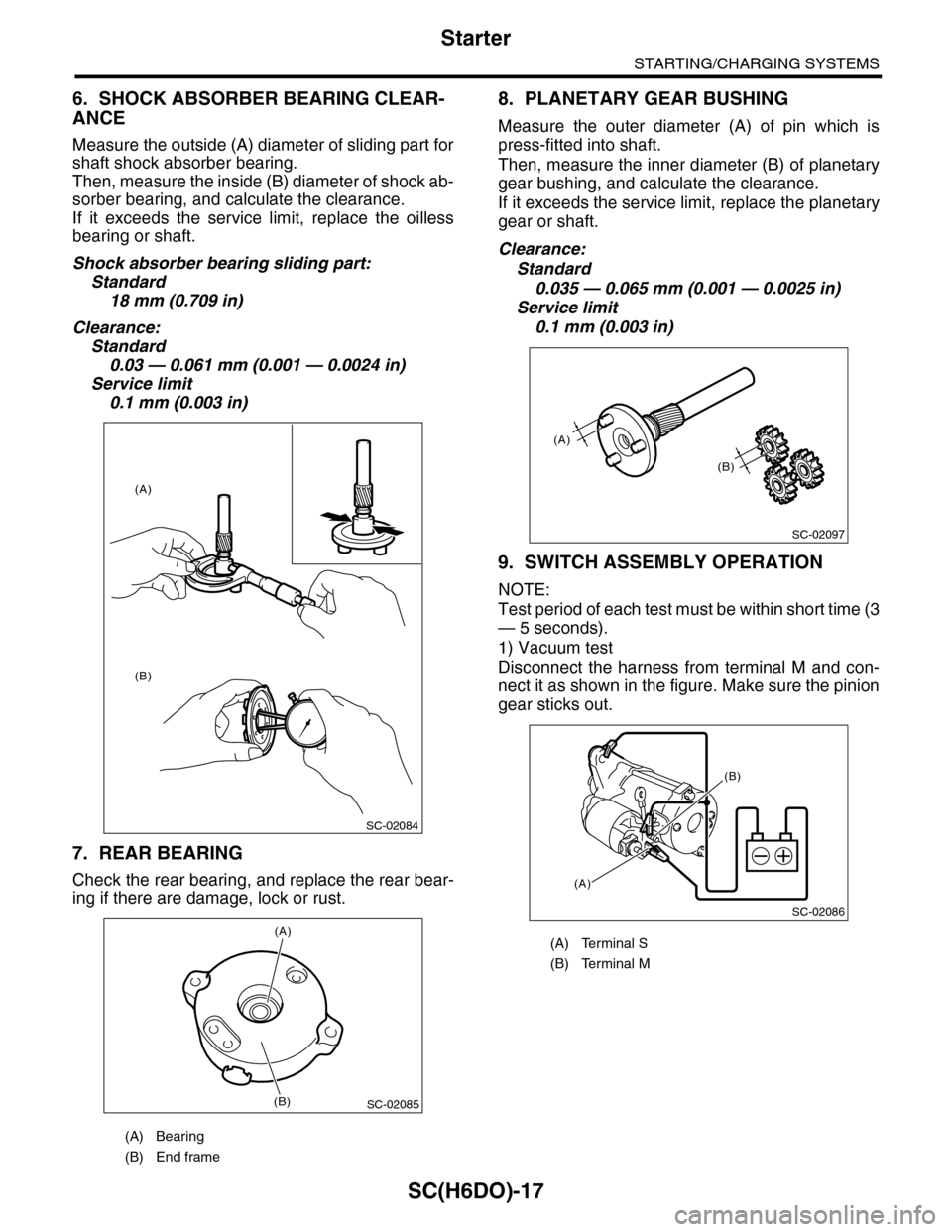
6. SHOCK ABSORBER BEARING CLEAR-
ANCE
Measure the outside (A) diameter of sliding part for
shaft shock absorber bearing.
Then, measure the inside (B) diameter of shock ab-
sorber bearing, and calculate the clearance.
If it exceeds the service limit, replace the oilless
bearing or shaft.
Shock absorber bearing sliding part:
Standard
18 mm (0.709 in)
Clearance:
Standard
0.03 — 0.061 mm (0.001 — 0.0024 in)
Service limit
0.1 mm (0.003 in)
7. REAR BEARING
Check the rear bearing, and replace the rear bear-
ing if there are damage, lock or rust.
8. PLANETARY GEAR BUSHING
Measure the outer diameter (A) of pin which is
press-fitted into shaft.
Then, measure the inner diameter (B) of planetary
gear bushing, and calculate the clearance.
If it exceeds the service limit, replace the planetary
gear or shaft.
Clearance:
Standard
0.035 — 0.065 mm (0.001 — 0.0025 in)
Service limit
0.1 mm (0.003 in)
9. SWITCH ASSEMBLY OPERATION
NOTE:
Test period of each test must be within short time (3
— 5 seconds).
1) Vacuum test
Disconnect the harness from terminal M and con-
nect it as shown in the figure. Make sure the pinion
gear sticks out.
(A) Bearing
(B) End frame
SC-02084
(A)
(B)
SC-02085
(A)
(B)
(A) Terminal S
(B) Terminal M
SC-02097
(A)
(B)
SC-02086
(A)
(B)
Page 2007 of 2453
PM-24
Suspension
PERIODIC MAINTENANCE SERVICES
17.Suspension
A: INSPECTION
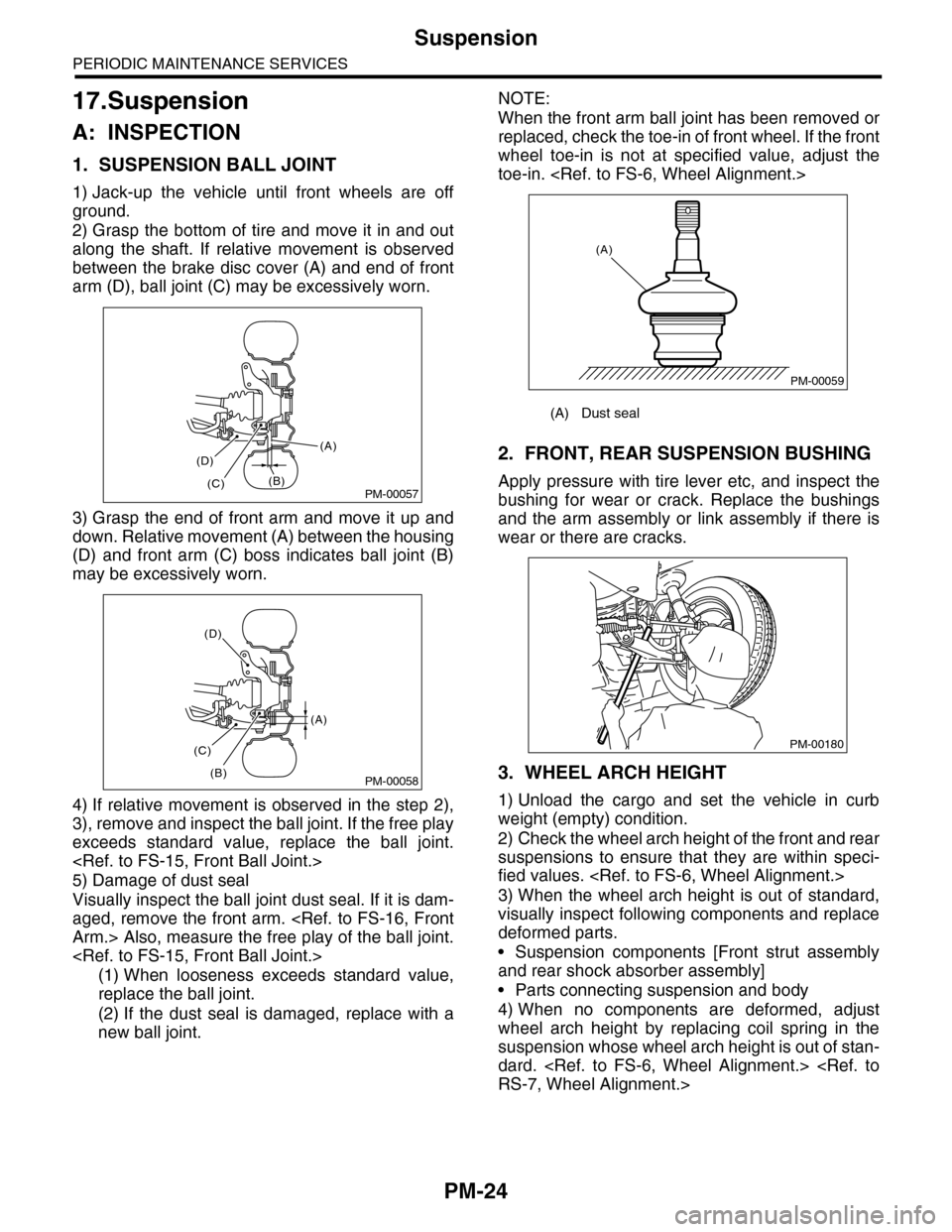
1. SUSPENSION BALL JOINT
1) Jack-up the vehicle until front wheels are off
ground.
2) Grasp the bottom of tire and move it in and out
along the shaft. If relative movement is observed
between the brake disc cover (A) and end of front
arm (D), ball joint (C) may be excessively worn.
3) Grasp the end of front arm and move it up and
down. Relative movement (A) between the housing
(D) and front arm (C) boss indicates ball joint (B)
may be excessively worn.
4) If relative movement is observed in the step 2),
3), remove and inspect the ball joint. If the free play
exceeds standard value, replace the ball joint.
5) Damage of dust seal
Visually inspect the ball joint dust seal. If it is dam-
aged, remove the front arm.
Arm.> Also, measure the free play of the ball joint.
(1) When looseness exceeds standard value,
replace the ball joint.
(2) If the dust seal is damaged, replace with a
new ball joint.
NOTE:
When the front arm ball joint has been removed or
replaced, check the toe-in of front wheel. If the front
wheel toe-in is not at specified value, adjust the
toe-in.
2. FRONT, REAR SUSPENSION BUSHING
Apply pressure with tire lever etc, and inspect the
bushing for wear or crack. Replace the bushings
and the arm assembly or link assembly if there is
wear or there are cracks.
3. WHEEL ARCH HEIGHT
1) Unload the cargo and set the vehicle in curb
weight (empty) condition.
2) Check the wheel arch height of the front and rear
suspensions to ensure that they are within speci-
fied values.
3) When the wheel arch height is out of standard,
visually inspect following components and replace
deformed parts.
•Suspension components [Front strut assembly
and rear shock absorber assembly]
•Parts connecting suspension and body
4) When no components are deformed, adjust
wheel arch height by replacing coil spring in the
suspension whose wheel arch height is out of stan-
dard.
RS-7, Wheel Alignment.>
PM-00057
(A)
(B)(C)
(D)
PM-00058
(A)
(B)
(C)
(D)
(A) Dust seal
PM-00059
(A)
PM-00180