2009 SUBARU TRIBECA engine coolant
[x] Cancel search: engine coolantPage 1865 of 2453
LU(H6DO)-16
Oil Cooler
LUBRICATION
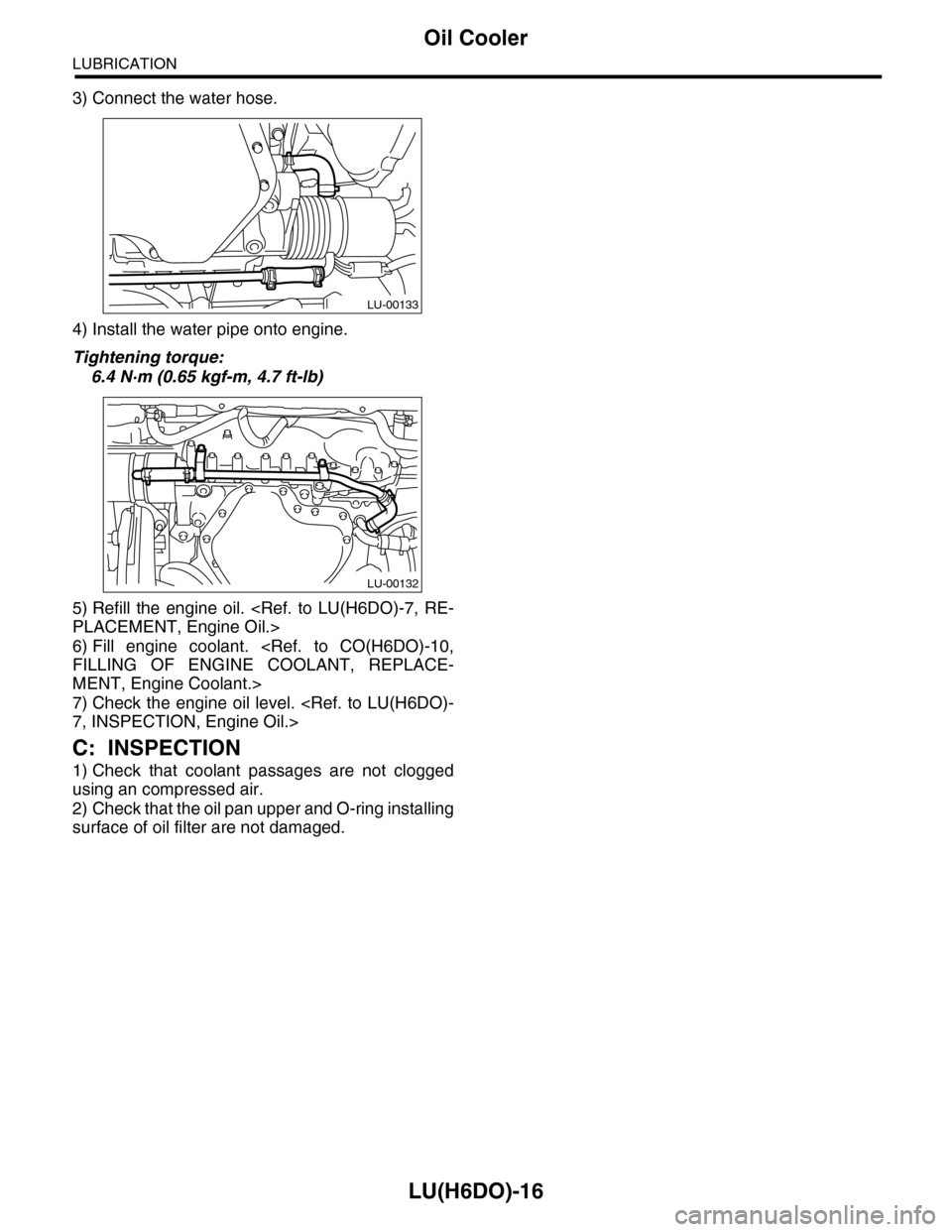
3) Connect the water hose.
4) Install the water pipe onto engine.
Tightening torque:
6.4 N·m (0.65 kgf-m, 4.7 ft-lb)
5) Refill the engine oil.
6) Fill engine coolant.
MENT, Engine Coolant.>
7) Check the engine oil level.
C: INSPECTION
1) Check that coolant passages are not clogged
using an compressed air.
2) Check that the oil pan upper and O-ring installing
surface of oil filter are not damaged.
LU-00133
LU-00132
Page 1880 of 2453
ME(H6DO)-14
General Description
MECHANICAL
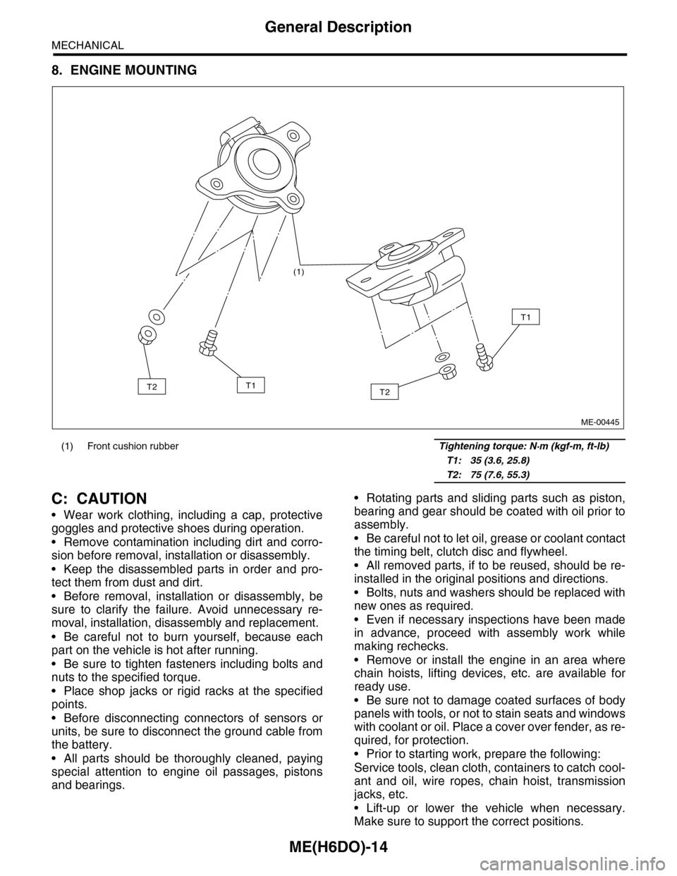
8. ENGINE MOUNTING
C: CAUTION
•Wear work clothing, including a cap, protective
goggles and protective shoes during operation.
•Remove contamination including dirt and corro-
sion before removal, installation or disassembly.
•Keep the disassembled parts in order and pro-
tect them from dust and dirt.
•Before removal, installation or disassembly, be
sure to clarify the failure. Avoid unnecessary re-
moval, installation, disassembly and replacement.
•Be careful not to burn yourself, because each
part on the vehicle is hot after running.
•Be sure to tighten fasteners including bolts and
nuts to the specified torque.
•Place shop jacks or rigid racks at the specified
points.
•Before disconnecting connectors of sensors or
units, be sure to disconnect the ground cable from
the battery.
•All parts should be thoroughly cleaned, paying
special attention to engine oil passages, pistons
and bearings.
•Rotating parts and sliding parts such as piston,
bearing and gear should be coated with oil prior to
assembly.
•Be careful not to let oil, grease or coolant contact
the timing belt, clutch disc and flywheel.
•All removed parts, if to be reused, should be re-
installed in the original positions and directions.
•Bolts, nuts and washers should be replaced with
new ones as required.
•Even if necessary inspections have been made
in advance, proceed with assembly work while
making rechecks.
•Remove or install the engine in an area where
chain hoists, lifting devices, etc. are available for
ready use.
•Be sure not to damage coated surfaces of body
panels with tools, or not to stain seats and windows
with coolant or oil. Place a cover over fender, as re-
quired, for protection.
•Prior to starting work, prepare the following:
Service tools, clean cloth, containers to catch cool-
ant and oil, wire ropes, chain hoist, transmission
jacks, etc.
•Lift-up or lower the vehicle when necessary.
Make sure to support the correct positions.
(1) Front cushion rubber Tightening torque: N·m (kgf-m, ft-lb)
T1: 35 (3.6, 25.8)
T2: 75 (7.6, 55.3)
(1)
T2
T1
T1T2
ME-00445
Page 1904 of 2453
ME(H6DO)-38
Engine Assembly
MECHANICAL
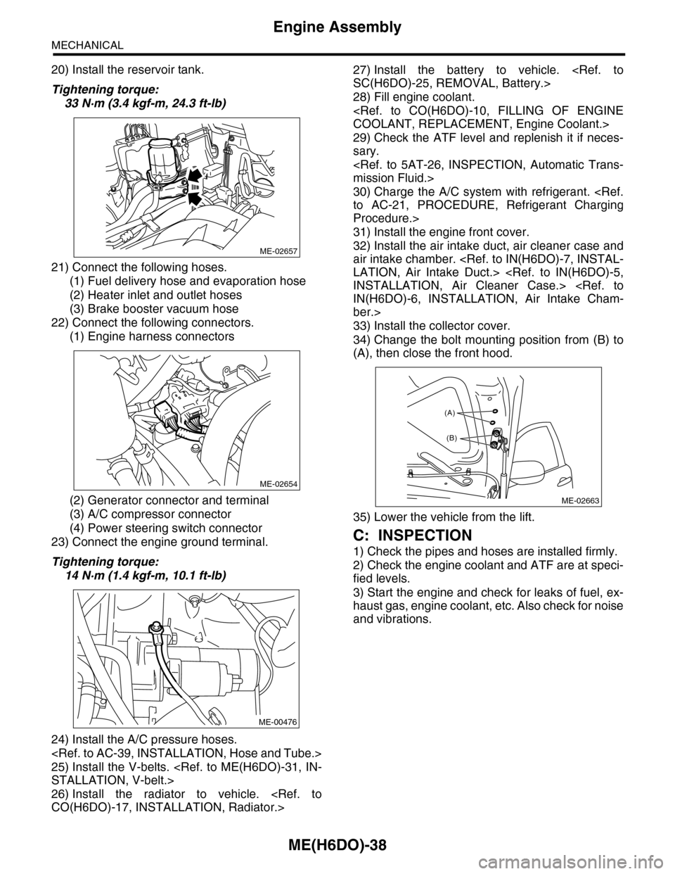
20) Install the reservoir tank.
Tightening torque:
33 N·m (3.4 kgf-m, 24.3 ft-lb)
21) Connect the following hoses.
(1) Fuel delivery hose and evaporation hose
(2) Heater inlet and outlet hoses
(3) Brake booster vacuum hose
22) Connect the following connectors.
(1) Engine harness connectors
(2) Generator connector and terminal
(3) A/C compressor connector
(4) Power steering switch connector
23) Connect the engine ground terminal.
Tightening torque:
14 N·m (1.4 kgf-m, 10.1 ft-lb)
24) Install the A/C pressure hoses.
25) Install the V-belts.
26) Install the radiator to vehicle.
27) Install the battery to vehicle.
28) Fill engine coolant.
29) Check the ATF level and replenish it if neces-
sary.
30) Charge the A/C system with refrigerant.
Procedure.>
31) Install the engine front cover.
32) Install the air intake duct, air cleaner case and
air intake chamber.
ber.>
33) Install the collector cover.
34) Change the bolt mounting position from (B) to
(A), then close the front hood.
35) Lower the vehicle from the lift.
C: INSPECTION
1) Check the pipes and hoses are installed firmly.
2) Check the engine coolant and ATF are at speci-
fied levels.
3) Start the engine and check for leaks of fuel, ex-
haust gas, engine coolant, etc. Also check for noise
and vibrations.
ME-02657
ME-02654
ME-00476
ME-02663
(A)
(B)
Page 1906 of 2453
ME(H6DO)-40
Preparation for Overhaul
MECHANICAL
12.Preparation for Overhaul
A: REMOVAL
1) Remove the engine assembly from the body.
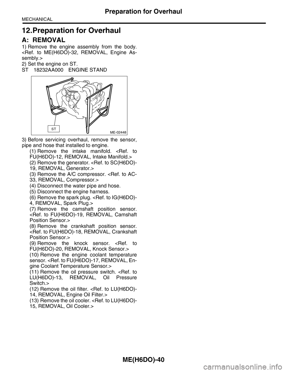
2) Set the engine on ST.
ST 18232AA000 ENGINE STAND
3) Before servicing overhaul, remove the sensor,
pipe and hose that installed to engine.
(1) Remove the intake manifold.
(2) Remove the generator.
(3) Remove the A/C compressor.
(4) Disconnect the water pipe and hose.
(5) Disconnect the engine harness.
(6) Remove the spark plug.
(7) Remove the camshaft position sensor.
(8) Remove the crankshaft position sensor.
(9) Remove the knock sensor.
(10) Remove the engine coolant temperature
sensor.
(11) Remove the oil pressure switch.
Switch.>
(12) Remove the oil filter.
(13) Remove the oil cooler.
STME-02448
Page 1986 of 2453
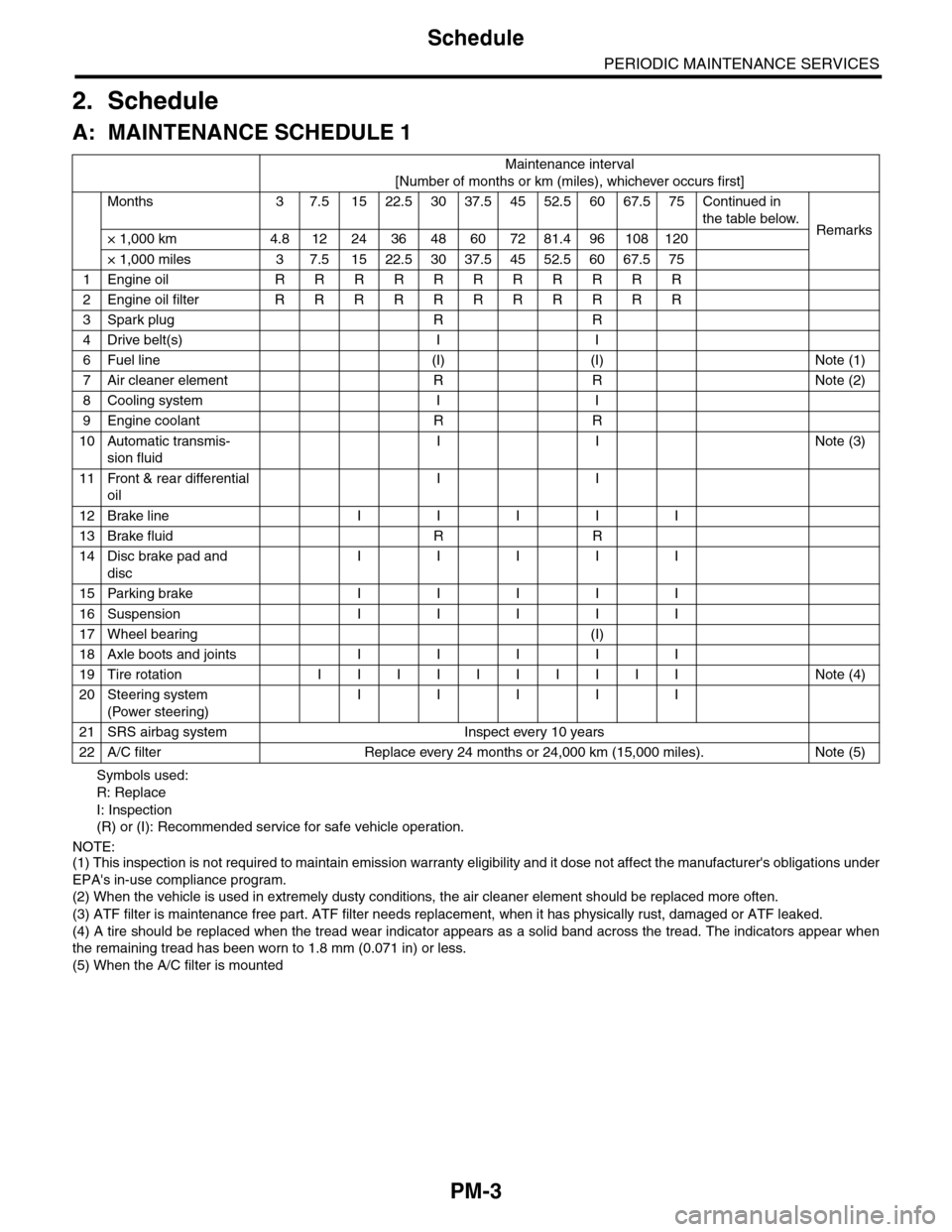
PM-3
Schedule
PERIODIC MAINTENANCE SERVICES
2. Schedule
A: MAINTENANCE SCHEDULE 1
Symbols used:
R: Replace
I: Inspection
(R) or (I): Recommended service for safe vehicle operation.
NOTE:(1) This inspection is not required to maintain emission warranty eligibility and it dose not affect the manufacturer's obligations under
EPA's in-use compliance program.
(2) When the vehicle is used in extremely dusty conditions, the air cleaner element should be replaced more often.
(3) ATF filter is maintenance free part. ATF filter needs replacement, when it has physically rust, damaged or ATF leaked.
(4) A tire should be replaced when the tread wear indicator appears as a solid band across the tread. The indicators appear when
the remaining tread has been worn to 1.8 mm (0.071 in) or less.
(5) When the A/C filter is mounted
Maintenance interval
[Number of months or km (miles), whichever occurs first]
Months 3 7.51522.53037.54552.56067.575Continued in
the table below.Remarks× 1,000 km 4.8 12 24 36 48 60 72 81.4 96 108 120
× 1,000 miles 3 7.5 15 22.5 30 37.5 45 52.5 60 67.5 75
1Engine oil R R R R R R R R R R R
2Engine oil filter R R R R R R R R R R R
3Spark plug R R
4Drive belt(s) I I
6Fuel line (I) (I) Note (1)
7Air cleaner element R R Note (2)
8Cooling system I I
9Engine coolant R R
10 Automatic transmis-
sion fluid
I I Note (3)
11 Front & rear differential
oil
I I
12 Brake line I I I I I
13 Brake fluid R R
14 Disc brake pad and
disc
I I I I I
15 Parking brake I I I I I
16 Suspension I I I I I
17 Wheel bearing (I)
18 Axle boots and joints I I I I I
19 Tire rotation I I I I I I I I I I Note (4)
20 Steering system
(Power steering)
I I I I I
21 SRS airbag system Inspect every 10 years
22 A/C filter Replace every 24 months or 24,000 km (15,000 miles). Note (5)
Page 1987 of 2453
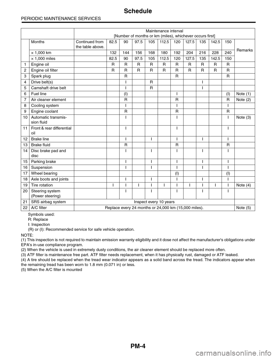
PM-4
Schedule
PERIODIC MAINTENANCE SERVICES
Symbols used:
R: Replace
I: Inspection
(R) or (I): Recommended service for safe vehicle operation.
NOTE:(1) This inspection is not required to maintain emission warranty eligibility and it dose not affect the manufacturer's obligations under
EPA's in-use compliance program.
(2) When the vehicle is used in extremely dusty conditions, the air cleaner element should be replaced more often.
(3) ATF filter is maintenance free part. ATF filter needs replacement, when it has physically rust, damaged or ATF leaked.
(4) A tire should be replaced when the tread wear indicator appears as a solid band across the tread. The indicators appear when
the remaining tread has been worn to 1.8 mm (0.071 in) or less.
(5) When the A/C filter is mounted
Maintenance interval
[Number of months or km (miles), whichever occurs first]
Months Continued from
the table above.
82.5 90 97.5 105112.5120127.5135142.5150
Remarks× 1,000 km 132 144 156 168 180 192 204 216 228 240
× 1,000 miles 82.5 90 97.5 105112.5120127.5135142.5150
1Engine oil R R R R R R R R R R
2Engine oil filter R R R R R R R R R R
3Spark plug R R R
4Drive belt(s) I R I
5Camshaft drive belt I R I
6Fuel line (I) I (I) Note (1)
7Air cleaner element R R R Note (2)
8Cooling system I I I
9Engine coolant R R R
10 Automatic transmis-
sion fluid
I I INote (3)
11 Front & rear differential
oil
I I I
12 Brake line I I I I I
13 Brake fluid R R R
14 Disc brake pad and
disc
I I I I I
15 Parking brake I I I I I
16 Suspension I I I I I
17 Wheel bearing (I) (I)
18 Axle boots and joints I I I I I
19 Tire rotation I I I I I I I I I I Note (4)
20 Steering system
(Power steering)
I I I I I
21 SRS airbag system Inspect every 10 years
22 A/C filter Replace every 24 months or 24,000 km (15,000 miles). Note (5)
Page 1990 of 2453
PM-7
Engine Oil
PERIODIC MAINTENANCE SERVICES
B: INSPECTION
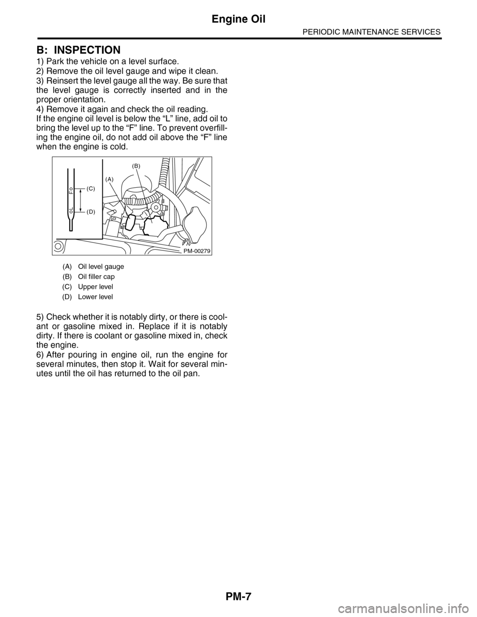
1) Park the vehicle on a level surface.
2) Remove the oil level gauge and wipe it clean.
3) Reinsert the level gauge all the way. Be sure that
the level gauge is correctly inserted and in the
proper orientation.
4) Remove it again and check the oil reading.
If the engine oil level is below the “L” line, add oil to
bring the level up to the “F” line. To prevent overfill-
ing the engine oil, do not add oil above the “F” line
when the engine is cold.
5) Check whether it is notably dirty, or there is cool-
ant or gasoline mixed in. Replace if it is notably
dirty. If there is coolant or gasoline mixed in, check
the engine.
6) After pouring in engine oil, run the engine for
several minutes, then stop it. Wait for several min-
utes until the oil has returned to the oil pan.
(A) Oil level gauge
(B) Oil filler cap
(C) Upper level
(D) Lower level
PM-00279
(A)
(B)
(C)
(D)
Page 1996 of 2453
PM-13
Cooling System
PERIODIC MAINTENANCE SERVICES
9. Cooling System
A: INSPECTION
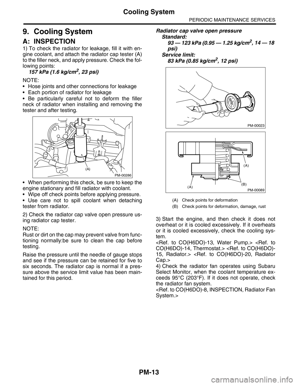
1) To check the radiator for leakage, fill it with en-
gine coolant, and attach the radiator cap tester (A)
to the filler neck, and apply pressure. Check the fol-
lowing points:
157 kPa (1.6 kg/cm2, 23 psi)
NOTE:
•Hose joints and other connections for leakage
•Each portion of radiator for leakage
•Be particularly careful not to deform the filler
neck of radiator when installing and removing the
tester and after testing.
•When performing this check, be sure to keep the
engine stationary and fill radiator with coolant.
•Wipe off check points before applying pressure.
•Use care not to spill coolant when detaching
tester from radiator.
2) Check the radiator cap valve open pressure us-
ing radiator cap tester.
NOTE:
Rust or dirt on the cap may prevent valve from func-
tioning normally:be sure to clean the cap before
testing.
Raise the pressure until the needle of gauge stops
and see if the pressure can be retained for five to
six seconds. The radiator cap is normal if a pres-
sure above the service limit value has been main-
tained for this period.
Radiator cap valve open pressure
Standard:
93 — 123 kPa (0.95 — 1.25 kg/cm2, 14 — 18
psi)
Service limit:
83 kPa (0.85 kg/cm2, 12 psi)
3) Start the engine, and then check it does not
overheat or it is cooled excessively. If it overheats
or it is cooled excessively, check the cooling sys-
tem.
4) Check the radiator fan operates using Subaru
Select Monitor, when the coolant temperature ex-
ceeds 95°C (203°F). If it does not operate, check
the radiator fan system.
PM-00286
(A)
(A) Check points for deformation
(B) Check points for deformation, damage, rust
PM-00023
PM-00089
(B)(A)
(A)