Page 314 of 2453

GW-19
Windshield Glass
GLASS/WINDOWS/MIRRORS
B: INSTALLATION
1) Clean the external circumference of windshield
glass with alcohol or white gasoline.
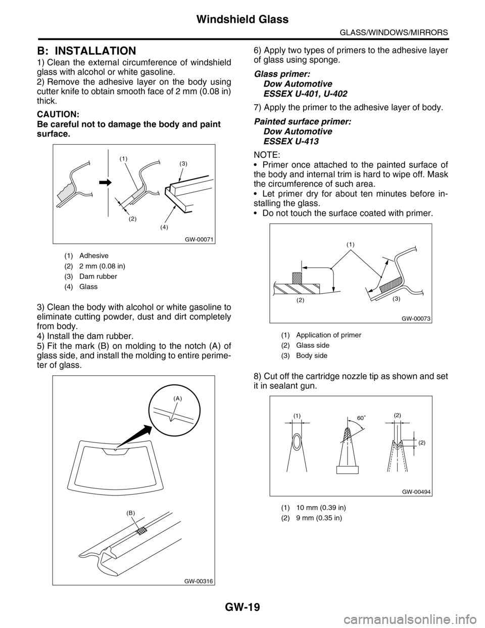
2) Remove the adhesive layer on the body using
cutter knife to obtain smooth face of 2 mm (0.08 in)
thick.
CAUTION:
Be careful not to damage the body and paint
surface.
3) Clean the body with alcohol or white gasoline to
eliminate cutting powder, dust and dirt completely
from body.
4) Install the dam rubber.
5) Fit the mark (B) on molding to the notch (A) of
glass side, and install the molding to entire perime-
ter of glass.
6) Apply two types of primers to the adhesive layer
of glass using sponge.
Glass primer:
Dow Automotive
ESSEX U-401, U-402
7) Apply the primer to the adhesive layer of body.
Painted surface primer:
Dow Automotive
ESSEX U-413
NOTE:
•Primer once attached to the painted surface of
the body and internal trim is hard to wipe off. Mask
the circumference of such area.
•Let primer dry for about ten minutes before in-
stalling the glass.
•Do not touch the surface coated with primer.
8) Cut off the cartridge nozzle tip as shown and set
it in sealant gun.
(1) Adhesive
(2) 2 mm (0.08 in)
(3) Dam rubber
(4) Glass
(4)
(2)
(1)(3)
GW-00071
GW-00316
(A)
(B)
(1) Application of primer
(2) Glass side
(3) Body side
(1) 10 mm (0.39 in)
(2) 9 mm (0.35 in)
(3)(2)
(1)
GW-00073
GW-00494
(1)(2)
(2)
60
Page 441 of 2453

IDI-2
General Description
INSTRUMENTATION/DRIVER INFO
1. General Description
A: SPECIFICATION
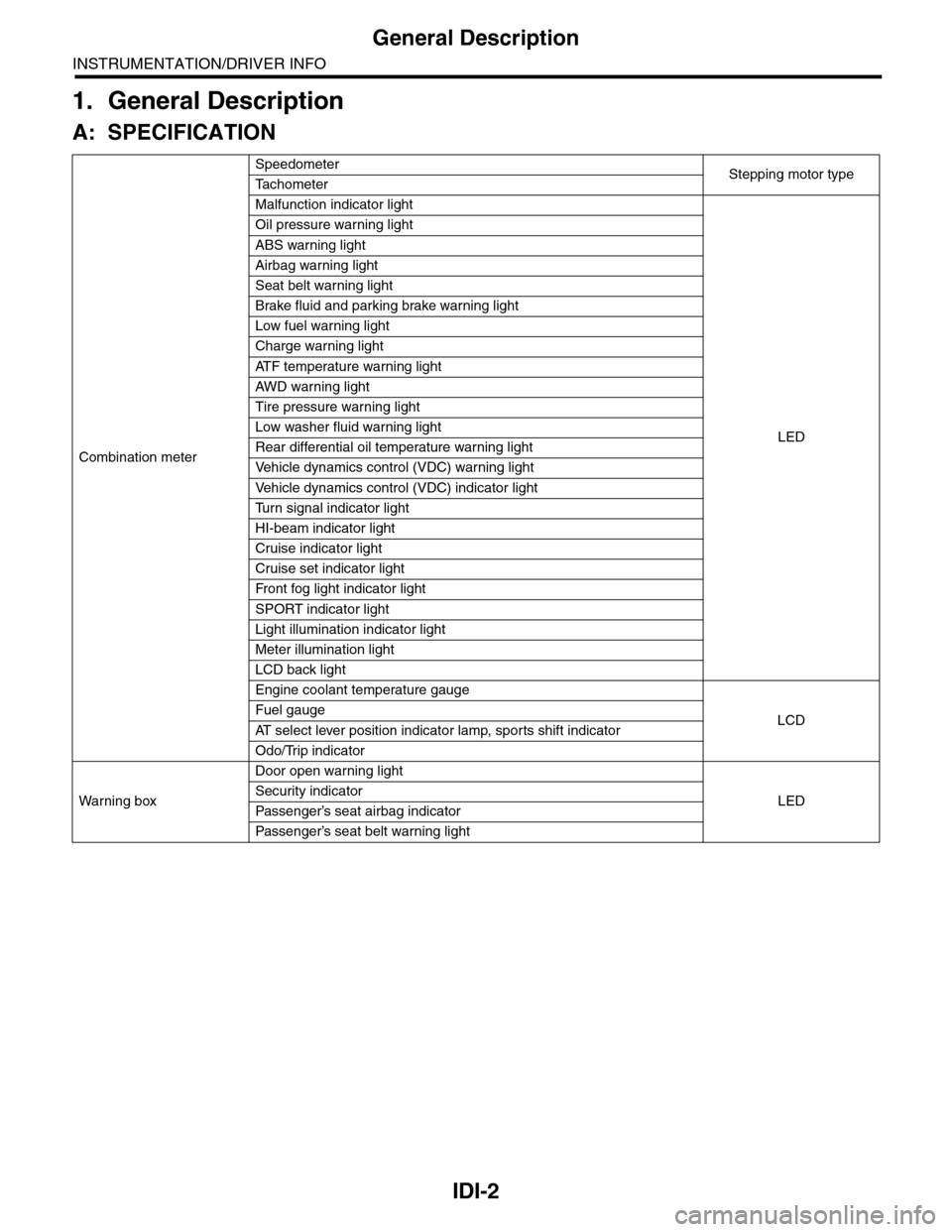
Combination meter
SpeedometerStepping motor typeTa c h o m e t e r
Malfunction indicator light
LED
Oil pressure warning light
ABS warning light
Airbag warning light
Seat belt warning light
Brake fluid and parking brake warning light
Low fuel warning light
Charge warning light
AT F t e m p e r a t u r e w a r n i n g l i g h t
AW D war n in g l i gh t
Tire pressure warning light
Low washer fluid warning light
Rear differential oil temperature warning light
Ve h i c l e d y n a m i c s c o n t r o l ( V D C ) w a r n i n g l i g h t
Ve h i c l e d y n a m i c s c o n t r o l ( V D C ) i n d i c a t o r l i g h t
Tu r n s i g n a l i n d i c a t o r l i g h t
HI-beam indicator light
Cruise indicator light
Cruise set indicator light
Fr o nt fog li g ht i nd i ca to r li g ht
SPORT indicator light
Light illumination indicator light
Meter illumination light
LCD back light
Engine coolant temperature gauge
LCDFuel gauge
AT s e l e c t l e v e r p o s i t i o n i n d i c a t o r l a m p , s p o r t s s h i f t i n d i c a t o r
Odo/Trip indicator
Wa r ni n g b ox
Door open warning light
LEDSecurity indicator
Passenger’s seat airbag indicator
Passenger’s seat belt war ning light
Page 544 of 2453

LI-11
Headlight Assembly
LIGHTING SYSTEM
10.Headlight Assembly
A: REMOVAL
1) Disconnect the ground cable from battery.
2) Remove the air intake duct.
3) Remove the engine front cover.
4) Disengage the three clips, and then turn over the
mud guard.
5) Remove the three bolts securing the headlight
assembly from the lower side of vehicle.
6) Remove the two bolts and then remove the
headlight assembly.
7) Disconnect the connector and then detach the
rear headlight assembly.
B: INSTALLATION
Install in the reverse order of removal.
C: ADJUSTMENT
1. HEADLIGHT AIMING
NOTE:
Aiming of this headlight can be adjusted only in the
vertical direction. It cannot be adjusted in the hori-
zontal direction.
CAUTION:
Turn off the light before adjusting the headlight
beam level. If it is necessary to inspect the
beam level, do not turn on the lamp for more
than two minutes.
NOTE:
Before checking the headlight beam level, be sure
of the following:
•Check the area around the headlight for any
scratches, damage or other type of deformation.
•Make sure that the vehicle is parked on a level
surface.
•Make sure that the inflation pressure of tires are
correct.
•Check that the vehicle fuel tank is full.
1) Bounce the vehicle several times to normalize
the suspension.
2) Make certain that someone is seated in the driv-
er's seat.
IN-02134
CO-02176
LI-00503
LI-00504
Page 786 of 2453

DI-2
General Description
DIFFERENTIALS
1. General Description
A: SPECIFICATION
1. REAR DIFFERENTIAL
When replacing a rear differential assembly, select the correct one according to the following table.
NOTE:
•Using a different rear differential assembly will cause the drive train and tires to drag or emit abnormal
noise.
•For option code, refer to “ID” section.
2. IDENTIFICATION
Identification label positions are shown in the fol-
lowing figures. For details concerning identification,
refer to the “ID” section.
3. REAR DIFFERENTIAL GEAR OIL
Recommended gear oil:
GL–5 (75W–90)
NOTE:
Each oil manufacturer has its base oil and addi-
tives. Thus, do not mix two or more brands.
4. SERVICE DATA
Rear differential type VA2-type
Identification XX
LSD type—
Ty p e o f g e a r H y p o i d g e a r
Gear ratio (Number of gear teeth) 3.583 (43/12)
Oil capacity 0.82 (0.8 US qt, 0.7 lmp qt)
Rear differential gear oil GL-5
(1) Identification
ID-00114
(1)
(1) Item
(2) Rear differential gear oil
(3) API classification
(4) SAE viscosity No. and applicable temperature
MT-00001
(1)
(4)GL-5(3)
(2)
( C)( F)-30 -26 -15 15
9085W80W75W -90
25 30 -5 0-22-1523328659775
Drive pinion bearing preload Measure with spring measurement. (Mea-
sured from the companion flange bolt)
N (kgf, lb)
12.7 — 32.2 (1.3 — 3.28, 2.9 — 7.24)
Measure with torque wrench
N·m (kgf–m, ft–lb)0.48 — 1.22 (0.045 — 0.124, 0.32 — 0.9)
Hypoid driven gear to drive pinion backlash mm (in) 0.10 — 0.15 (0.0039 — 0.0059)
Page 798 of 2453
DI-14
Rear Differential (VA–type)
DIFFERENTIALS
4. Rear Differential (VA–type)
A: REMOVAL
1) Disconnect the ground cable from the battery.
2) Release the parking brake.
3) Jack-up the vehicle.
4) Remove the rear exhaust pipe and muffler.
Pipe.>
5) Remove the heat shield cover.
6) Remove the propeller shaft.
7) Remove the connector from the rear differential
oil temperature switch.
8) Prepare the transmission jack and band.
9) Remove the DOJ of rear drive shaft from rear dif-
ferential.
10) Remove the nuts which hold the rear differen-
tial front member.
11) Support the rear differential with the transmis-
sion jack.
12) Loosen the self-lock nuts which hold the rear
differential to rear crossmember.
AT-03243
DI-00471
DI-00268
(A) Tire lever
(B) Bolt
DI-00472
(A)
(B)
DI-00358
DI-00473
DI-00269
Page 799 of 2453

DI-15
Rear Differential (VA–type)
DIFFERENTIALS
13) Remove the rear differential front member.
14) Secure the rear differential using band.
15) Remove the self-lock nuts which hold the rear
differential to rear crossmember.
16) Remove the air breather hose from the sub
frame.
17) Remove the rear differential stud bolt from rear
crossmember bushing.
NOTE:
When removing the stud bolt, carefully adjust the
angle and location of transmission jack and jack
stand, if necessary
18) Pull out the axle shaft from rear differential.
NOTE:
If it is difficult to remove the axle shaft from rear dif-
ferential, remove it using tire lever.
19) Lower the transmission jack.
20) Secure the rear drive shaft to lateral link using
wire.
21) Remove the rear differential member plate from
rear differential.
B: INSTALLATION
1) Insert the rear differential member plate into rear
differential.
2) Set the rear differential to transmission jack.
NOTE:
Secure the rear differential to transmission jack us-
ing band.
3) Install the ST to rear differential.
ST 28099PA090 OIL SEAL PROTECTOR
DI-00474
DI-00276
DI-00277
(A) Rear differential member plate
(A) Rear differential member plate
DI-00475
(A)
DI-00475
(A)
DI-00476
ST
Page 1000 of 2453
VDC(diag)-8
Check List for Interview
VEHICLE DYNAMICS CONTROL (VDC) (DIAGNOSTICS)
Condition a) Brakes Deceleration: G
continuous / intermittent
b) Accelerator Acceleration: G
continuous / intermittent
c) Vehicle speed km/h MPH
Advancing
Accelerating
Reducing speed
Low speed
Turning
Others:
d) Tire inflation pressure Front RH tire: kPa
Fr o n t L H t ir e : kPa
Rear RH tire: kPa
Rear LH tire: kPa
e) Degree of wear Front RH tire:
Fr o n t L H t ir e :
Rear RH tire:
Rear LH tire:
f) Steering wheel Sharp turning
Gentle turning
Straight forward motion
Gentle return
Sharp return
g) Tire/Wheel size Specified size
Except specification ( )
h) Tire variation Summer tire
Studless tire (Brand: )
i) Tire chains are fitted: Yes / No
j) T-type tire is used: Yes / No
k) Condition of suspension alignment:
l) Loading state:
m) Repair parts are used: Yes / No
• Contents:
n) Others:
Page 1108 of 2453

WT-2
General Description
WHEEL AND TIRE SYSTEM
1. General Description
A: SPECIFICATION
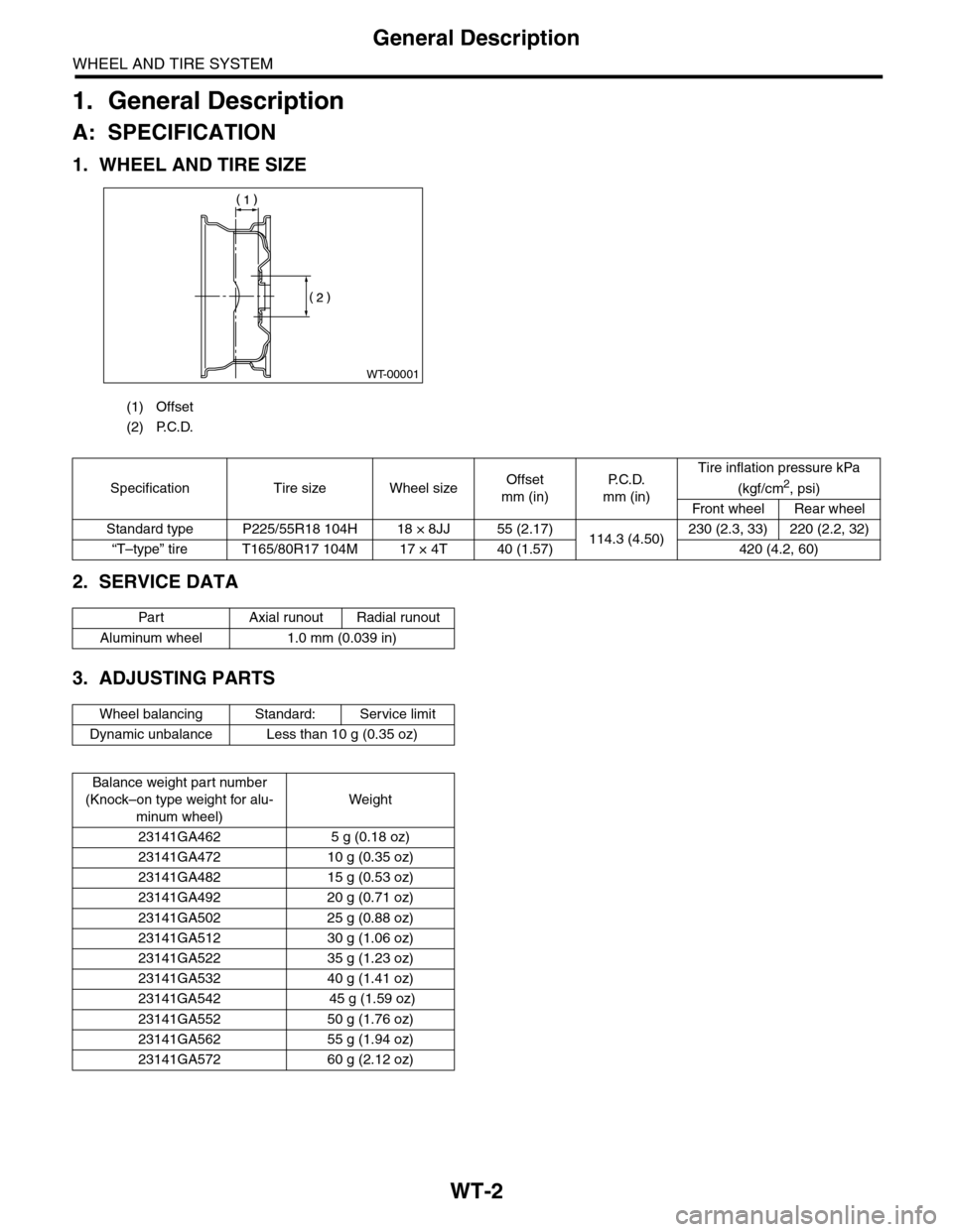
1. WHEEL AND TIRE SIZE
2. SERVICE DATA
3. ADJUSTING PARTS
(1) Offset
(2) P.C.D.
WT-00001
Specification Tire size Wheel sizeOffset
mm (in)
P. C . D .
mm (in)
Tire inflation pressure kPa
(kgf/cm2, psi)
Front wheel Rear wheel
Standard type P225/55R18 104H 18 × 8JJ 55 (2.17)114.3 (4.50)230 (2.3, 33) 220 (2.2, 32)
“T–type” tire T165/80R17 104M 17 × 4T 40 (1.57) 420 (4.2, 60)
Par t Axial r unout Radial r unout
Aluminum wheel 1.0 mm (0.039 in)
Wheel balancing Standard: Service limit
Dynamic unbalance Less than 10 g (0.35 oz)
Balance weight par t number
(Knock–on type weight for alu-
minum wheel)
Weight
23141GA462 5 g (0.18 oz)
23141GA472 10 g (0.35 oz)
23141GA482 15 g (0.53 oz)
23141GA492 20 g (0.71 oz)
23141GA502 25 g (0.88 oz)
23141GA512 30 g (1.06 oz)
23141GA522 35 g (1.23 oz)
23141GA532 40 g (1.41 oz)
23141GA542 45 g (1.59 oz)
23141GA552 50 g (1.76 oz)
23141GA562 55 g (1.94 oz)
23141GA572 60 g (2.12 oz)