Page 1109 of 2453

WT-3
General Description
WHEEL AND TIRE SYSTEM
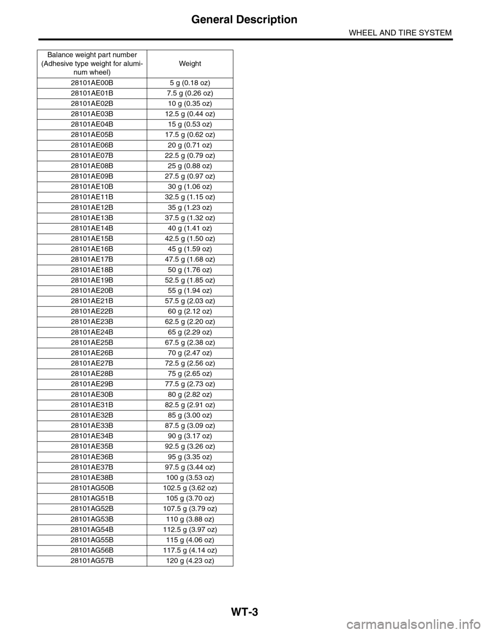
Balance weight par t number
(Adhesive type weight for alumi-
num wheel)
Weight
28101AE00B 5 g (0.18 oz)
28101AE01B 7.5 g (0.26 oz)
28101AE02B 10 g (0.35 oz)
28101AE03B 12.5 g (0.44 oz)
28101AE04B 15 g (0.53 oz)
28101AE05B 17.5 g (0.62 oz)
28101AE06B 20 g (0.71 oz)
28101AE07B 22.5 g (0.79 oz)
28101AE08B 25 g (0.88 oz)
28101AE09B 27.5 g (0.97 oz)
28101AE10B 30 g (1.06 oz)
28101AE11B 32.5 g (1.15 oz)
28101AE12B 35 g (1.23 oz)
28101AE13B 37.5 g (1.32 oz)
28101AE14B 40 g (1.41 oz)
28101AE15B 42.5 g (1.50 oz)
28101AE16B 45 g (1.59 oz)
28101AE17B 47.5 g (1.68 oz)
28101AE18B 50 g (1.76 oz)
28101AE19B 52.5 g (1.85 oz)
28101AE20B 55 g (1.94 oz)
28101AE21B 57.5 g (2.03 oz)
28101AE22B 60 g (2.12 oz)
28101AE23B 62.5 g (2.20 oz)
28101AE24B 65 g (2.29 oz)
28101AE25B 67.5 g (2.38 oz)
28101AE26B 70 g (2.47 oz)
28101AE27B 72.5 g (2.56 oz)
28101AE28B 75 g (2.65 oz)
28101AE29B 77.5 g (2.73 oz)
28101AE30B 80 g (2.82 oz)
28101AE31B 82.5 g (2.91 oz)
28101AE32B 85 g (3.00 oz)
28101AE33B 87.5 g (3.09 oz)
28101AE34B 90 g (3.17 oz)
28101AE35B 92.5 g (3.26 oz)
28101AE36B 95 g (3.35 oz)
28101AE37B 97.5 g (3.44 oz)
28101AE38B 100 g (3.53 oz)
28101AG50B 102.5 g (3.62 oz)
28101AG51B 105 g (3.70 oz)
28101AG52B 107.5 g (3.79 oz)
28101AG53B 110 g (3.88 oz)
28101AG54B 112.5 g (3.97 oz)
28101AG55B 115 g (4.06 oz)
28101AG56B 117.5 g (4.14 oz)
28101AG57B 120 g (4.23 oz)
Page 1114 of 2453

WT-8
Wheel Balancing
WHEEL AND TIRE SYSTEM
4. Wheel Balancing
A: ADJUSTMENT
NOTE:
The balance weight for the outside of the wheel
uses an adhesive type weight. Change the setting
of the wheel balancer to an adhesive type weight.
1) Remove the balance weights.
CAUTION:
•Be careful not to damage the wheel.
•Completely remove the double–sided tape of
the adhesive type weight from the wheel.
2) Using the wheel balancer, measure wheel bal-
ance.
3) Select a weight close to the value measured by
wheel balancer.
CAUTION:
Use SUBARU genuine balance weights.
4) Install the selected weight to the point designat-
ed by the wheel balancer.
CAUTION:
•Remove grease from adhesive type weight
applying surface of wheel.
•Press the adhesive type weight by 25 N (2.5
kgf, 5.6 lb) or more per 5 g (0.18 oz) for more
then 2 seconds and attain full adhesion.
•The total weight of all adhesive weight on
models with transmitters (tire pressure sensor)
is to be 120 g (4.23 oz) or less.
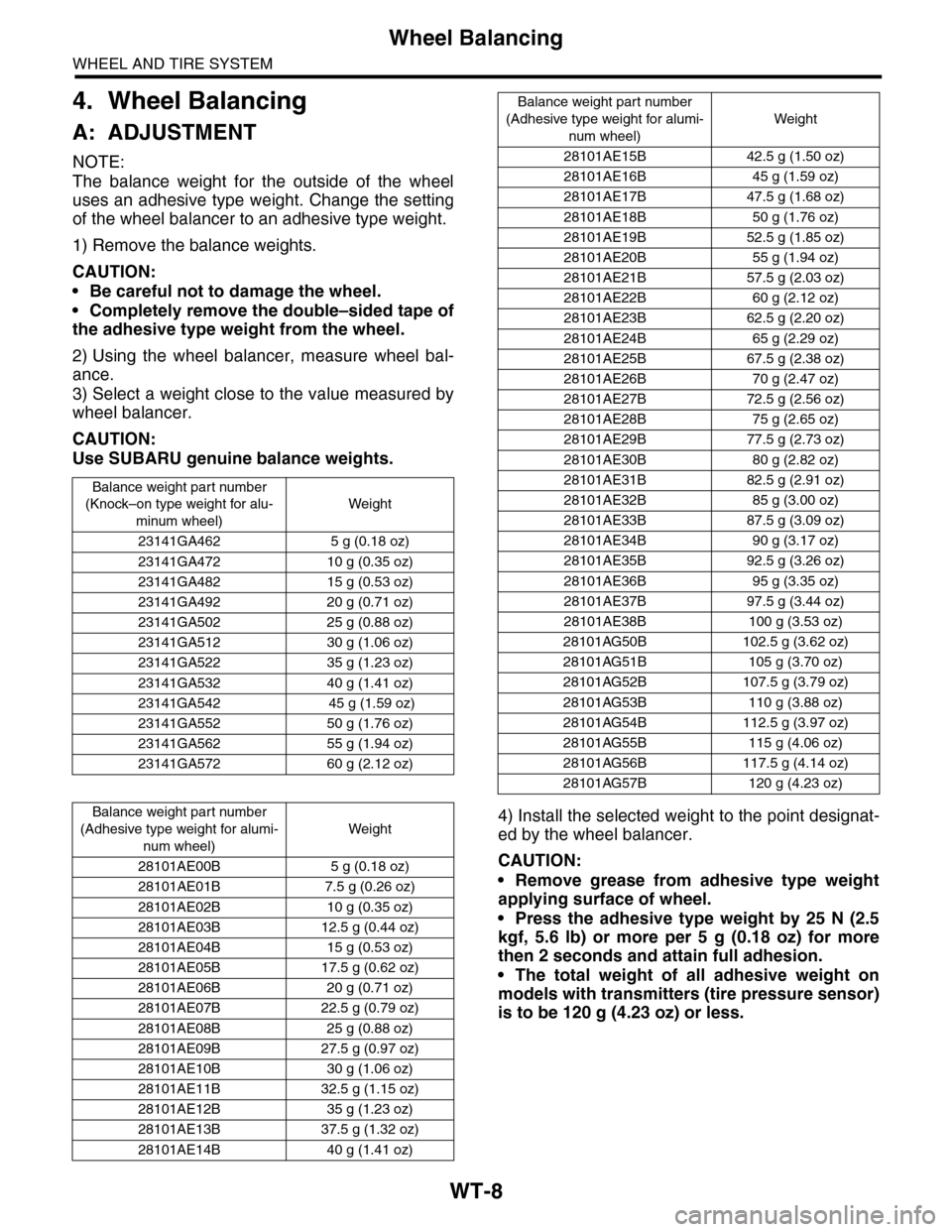
Balance weight par t number
(Knock–on type weight for alu-
minum wheel)
Weight
23141GA462 5 g (0.18 oz)
23141GA472 10 g (0.35 oz)
23141GA482 15 g (0.53 oz)
23141GA492 20 g (0.71 oz)
23141GA502 25 g (0.88 oz)
23141GA512 30 g (1.06 oz)
23141GA522 35 g (1.23 oz)
23141GA532 40 g (1.41 oz)
23141GA542 45 g (1.59 oz)
23141GA552 50 g (1.76 oz)
23141GA562 55 g (1.94 oz)
23141GA572 60 g (2.12 oz)
Balance weight par t number
(Adhesive type weight for alumi-
num wheel)
Weight
28101AE00B 5 g (0.18 oz)
28101AE01B 7.5 g (0.26 oz)
28101AE02B 10 g (0.35 oz)
28101AE03B 12.5 g (0.44 oz)
28101AE04B 15 g (0.53 oz)
28101AE05B 17.5 g (0.62 oz)
28101AE06B 20 g (0.71 oz)
28101AE07B 22.5 g (0.79 oz)
28101AE08B 25 g (0.88 oz)
28101AE09B 27.5 g (0.97 oz)
28101AE10B 30 g (1.06 oz)
28101AE11B 32.5 g (1.15 oz)
28101AE12B 35 g (1.23 oz)
28101AE13B 37.5 g (1.32 oz)
28101AE14B 40 g (1.41 oz)
28101AE15B 42.5 g (1.50 oz)
28101AE16B 45 g (1.59 oz)
28101AE17B 47.5 g (1.68 oz)
28101AE18B 50 g (1.76 oz)
28101AE19B 52.5 g (1.85 oz)
28101AE20B 55 g (1.94 oz)
28101AE21B 57.5 g (2.03 oz)
28101AE22B 60 g (2.12 oz)
28101AE23B 62.5 g (2.20 oz)
28101AE24B 65 g (2.29 oz)
28101AE25B 67.5 g (2.38 oz)
28101AE26B 70 g (2.47 oz)
28101AE27B 72.5 g (2.56 oz)
28101AE28B 75 g (2.65 oz)
28101AE29B 77.5 g (2.73 oz)
28101AE30B 80 g (2.82 oz)
28101AE31B 82.5 g (2.91 oz)
28101AE32B 85 g (3.00 oz)
28101AE33B 87.5 g (3.09 oz)
28101AE34B 90 g (3.17 oz)
28101AE35B 92.5 g (3.26 oz)
28101AE36B 95 g (3.35 oz)
28101AE37B 97.5 g (3.44 oz)
28101AE38B 100 g (3.53 oz)
28101AG50B 102.5 g (3.62 oz)
28101AG51B 105 g (3.70 oz)
28101AG52B 107.5 g (3.79 oz)
28101AG53B 110 g (3.88 oz)
28101AG54B 112.5 g (3.97 oz)
28101AG55B 115 g (4.06 oz)
28101AG56B 117.5 g (4.14 oz)
28101AG57B 120 g (4.23 oz)
Balance weight part number
(Adhesive type weight for alumi-
num wheel)
Weight
Page 1115 of 2453
WT-9
Wheel Balancing
WHEEL AND TIRE SYSTEM
5) Using the wheel balancer, measure the wheel
balance again. Check that wheel balance is cor-
rectly adjusted.
NOTE:
Knock-on type balance weights for aluminum
wheels are available for use with any 15 to 18 inch
wheels.
Service limit:
Knock-on type weight for aluminum wheels:
5—25 g (0.18—0.88 oz) 5.0 mm (0.20 in)
30 g (1.06 oz) or more 4.5 mm (0.177 in)
(1) Knock-on type weight for aluminum wheels
Page 1116 of 2453
WT-10
“T–type” Tire
WHEEL AND TIRE SYSTEM
5. “T–type” Tire
A: NOTE
“T–type” tire for temporary use is equipped as a
spare tire.
CAUTION:
•Do not drive at a speed greater than 100 km/h
(62 MPH).
•For the model with tire pressure monitoring
system, the indicator light may blink when run-
ning with the “T-type” tire.
B: REPLACEMENT
Refer to Aluminum Wheels for removal and instal-
lation procedures of the “T–type”.
REMOVAL, Aluminum Wheel.>
CAUTION:
The “T–type” tire is only for temporary use. Re-
place with a conventional tire as soon as possi-
ble.
C: INSPECTION
1) Check the tire air pressure.
Specifications:
420 kPa (4.2 kg/cm2, 60 psi)
2) Take stones, glass, nails, etc. out of the tread
groove.
3) Check the tires for deformation, cracks, partial
wear, or wear.
CAUTION:
Replace the tire with a new one if defective.
Page 2295 of 2453

WI-11
Basic Diagnostic Procedure
WIRING SYSTEM
1. RELAY
A symbol used to indicate a relay.
2. CONNECTOR 1
The sketch of the connector indicates the one-pole
types.
3. WIRING CONNECTION
Some wiring diagrams are indicated in foldouts for
convenience. Wiring destinations are indicated
where necessary by corresponding symbols.
(When two pages are needed for clear indication)
4. FUSE NO. & RATING
The “FUSE No. & RATING“ corresponds with that
used in the fuse box (main fuse box, fuse and joint
box).
5. CONNECTOR 2
•Each connector is indicated by a symbol.
•Each terminal number is indicated in the corre-
sponding wiring diagram in an abbreviated form.
•For example, terminal number "G4" refers to No.
4 terminal of connector (G: F41) shown in the con-
nector sketch.
6. CONNECTOR SKETCH
•Each connector sketch clearly identifies the
shape and color of a connector as well as terminal
locations. Non-colored connectors are indicated in
white or natural color.
•When more than two types of connector number
are indicated in a connector sketch, it means that
the same type connectors are used.
7. GROUND
Each grounding point can be located easily by re-
ferring to the corresponding wiring harness.
8. DIODE
A symbol is used to indicate a diode.
9. WIRE TRACING ON EXTENDED WIRING
DIAGRAMS
For a wiring diagram extending over at least two
pages, a symbol (consisting of the same characters
with arrows), facilitates wire tracing from one page
to the next.
A ←→ B, B ←→ B
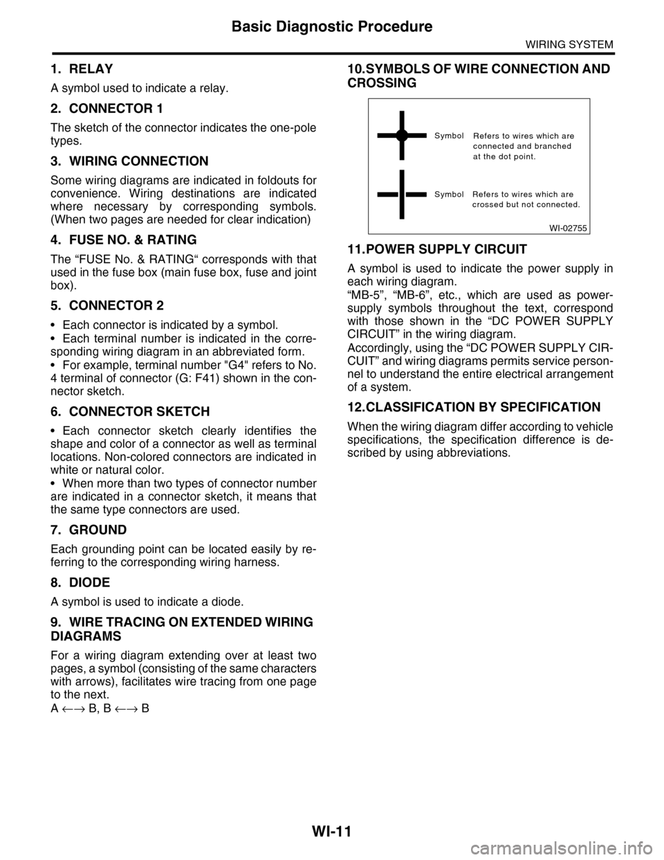
10.SYMBOLS OF WIRE CONNECTION AND
CROSSING
11.POWER SUPPLY CIRCUIT
A symbol is used to indicate the power supply in
each wiring diagram.
“MB-5”, “MB-6”, etc., which are used as power-
supply symbols throughout the text, correspond
with those shown in the “DC POWER SUPPLY
CIRCUIT” in the wiring diagram.
Accordingly, using the “DC POWER SUPPLY CIR-
CUIT” and wiring diagrams permits service person-
nel to understand the entire electrical arrangement
of a system.
12.CLASSIFICATION BY SPECIFICATION
When the wiring diagram differ according to vehicle
specifications, the specification difference is de-
scribed by using abbreviations.
WI-02755
Symbol
Symbol Refers to wires which arecrossed but not connected.
Refers to wires which areconnected and branchedat the dot point.