Page 209 of 284

203
Self-help, vehicle care
5. Unscrew the wheel bolts. If the wheel bolts have retaining
washers 3, they must not be removed.
6. Change wheel. Notes on spare wheel 3197. Notes on temporary spare wheel
3 197.
Picture no: 17249t.tif
7. Screw in the wheel bolts. Push the wheel
bolt wrench 3 on as far as possible and
tighten the wheel bolts slightly.
8. Lower vehicle.
9. Push the wheel bolt wrench 3 on as far
as possible and tighten crosswise.
Tightening torque is 110 Nm. 10. Before refitting the wheel trim, clean the
wheel around the retaining clips. Valve
symbol 3 on back of wheel trim must
point towards valve on wheel.
Align and refit wheel trim or wheel bolt
caps 3.
Alloy wheels 3: Align and refit wheel
bolt caps 3.
11. Stow removed wheel, tool kit and warning triangle 3 in the luggage
compartment 3196 to 3198.
12. Check the tyre pressure of the newly mounted wheel.
13. Have the wheel bolt tightening torque (110 Nm) checked.
14. Replace the faulty tyre on the wheel that was removed.
15. Initialise deflation detection system 3
3 164.
Back to overview
Page 210 of 284

204 Self-help, vehicle careTyre repair kit
3
Minor damage to the tyre tread or side wall
can be repaired using the tyre repair kit
(does not apply to run-flat tyres).
Do not remove the foreign body from the
tyre.
T y r e d a m a g e e x c e e d i n g 4 m m o r t ha t i s o n
the rim cannot be repaired with the tyre
repair kit.
Important 3207.
In the event of a flat tyre:
z Switch on hazard warning lights, apply
handbrake, engage 1st or reverse gear,
in the case of automatic transmission 3
move selector lever to position P.
z Erect warning triangle 3 as specified.
Warning triangle 3196.
Picture no: 18317s.tif
The tyre repair kit is located in the
compartment to the right in the luggage
compartment.
To open the compartment, disengage the
cover and open it.
Picture no: 18318s.tif
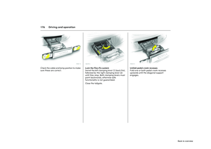
1. Remove the sealant bottle and holder
with the air tube from the compartment.
9
Warning
Do not drive faster than 80 km/h.
Do not use the temporary spare wheel
for a lengthy period.
Steering and handling may be affected.
Back to overview
Page 211 of 284
205
Self-help, vehicle care
Picture no: 17252t.tif
2. Unwind the air tube from the holder and screw onto the sealant bottle connector.
Picture no: 17468t.tif
3. Place the sealant bottle on the holder as shown in the illustrati on. Make sure that
the bottle does not fall over.
Picture no: 17469t.tif
4. Remove the valve cap from the defective
tyre.
5. Screw the filler hose to the tyre valve.
Back to overview
Page 212 of 284

206 Self-help, vehicle care
Picture no: 18427s.tif
6. Screw the air tube to the connector on the compressor.
7. Switch on ignition. To prevent battery discharge, we
recommend that you leave the engine
running.
Picture no: 18428s.tif
8. Press button < on the compressor, the
tyre is filled with the sealant.
9. While the sealant bottle drains (approx. 30 seconds) the pressure
indicator on the comp ressor briefly points
to 6 bar. Pressure then sinks again. 10. All of the sealant is
pumped into the tyre.
Afterwards, the tyre is filled with air.
11. The prescribed tyre pressure 3264,
should be attained within 10 minutes.
Once the pressure is attained, switch off
the compressor by pressing button <
again.
If the prescribed tyre pressure is not
obtained within 10 minutes, remove the
tyre repair kit. Move the vehicle one tyre
rotation. Reattach the tyre repair kit
and continue the filling procedure for
10 minutes. If the prescribed tyre
pressure is still not obtained, the tyre is
too badly damaged. Seek the
assistance of a workshop.
Release excess tyre pressure using
button ].
Do not operate the compressor for
more than 10 minutes, see "Important"
3 207.
Back to overview
Page 213 of 284

207
Self-help, vehicle care
12. Dismantle the tyre repair kit. When removing the sealant bottle from the
holder, press the ratchet on the holder.
Screw the tyre filler tube onto the free
connector on the sealant bottle. This
prevents the sealant from escaping.
Stow the tyre repair kit in the luggage
compartment.
13. Wipe away any sealant spill with a cloth.
14. Fold away warning triangle 3, store in
luggage compartment 3196.
15. Apply the sticker on the sealant bottle showing the maximum permitted speed
within the line of sight of the driver.
Sticker 3205, Fig. 17469 T. 16. Continue driving immediately so that
the sealant is distributed evenly
inside the tyre. After approx. 10 km
(after 10 minutes at the latest), stop
and check the tyre pressure. To do this,
screw an air tube directly to the tyre
valve and compressor.
If tyre pressure is more than 1.3 bar,
adjust to the prescribed value. Repeat
the procedure until there is no more
pressure loss.
If the tyre pressure has dropped
below 1.3 bar, the vehicle must not
be used. Contact a workshop for
assistance.
17. Stow the tyre repair kit behind the cover on the right in the side trim in the
luggage compartment. To close, lower
the cover and engage in the trim. Important
The driving comfort of the repaired tyre is
severely affected, therefore have this tyre
replaced.
If the compressor makes abnormal noises
or heats up greatly, switch it off for at
least 30 minutes.
The integrated safety valve opens at a
pressure of 7 bar.
Protect the compressor from moisture and
rain.
The sealant can only be stored for
approx. 4 years. After this time, the sealing
properties can no longer be guaranteed.
Heed the expiration
date on the sealant
bottle.
Replace the used sealant bottle. Dispose of
the bottle as prescrib ed by applicable laws.
The compressor and sealant can be used
from approx. -30 C.
The adapter 3 supplied may be used to
pump up other objects, such as balls,
airbeds, dinghies.
When using the tyre repair kit, no consumer
may be connected to the front accessory
socket at the same time.
Back to overview
Page 214 of 284
208 Self-help, vehicle careElectrical system Fuses
Data on the replacement fuse must match
the data on the defective fuse.
There are three fuse boxes in the vehicle:
zfront left, in the engine compartment,
z in the interior behind the light switch, or,
in right-hand drive cars, behind the
glove compartment,
z on the left of the luggage compartment,
behind a cover.
Before replacing a fuse, turn off the
respective switch and the ignition.
A blown fuse can be recognised by its
melted wire. Do not replace the fuse until
the cause of the fault has been remedied.
Only fit fuses of the specified current
rating. Each fuse has its current rating
written on it, the ratings are also colour
coded.
Picture no: 17259t.tif
Some functions are protected by several
fuses.
There may be fuses inserted with no
function.
Picture no: 17260t.tif
Different versions of fuses are used.
Back to overview
Page 215 of 284
209
Self-help, vehicle care
Picture no: 18588s.tif
Fuses and the most important
circuits they protectFuse box in engine compartment
The fuse box is at the front left side of the
engine compartment.
To open, disengage the cover, fold cover
up and remove.
Picture no: 18589s.tif Picture no:
No. Circuit
1 Starter
2 Air conditioning system
3 Diesel fuel filter heater
4 Horn
5 Manual transmission automated,
automatic transmission
6 Engine control unit
7 Fog lamps
8 Engine cooling
9 Engine cooling
No. Circuit
10 Automated manual transmission
11 Glow plugs, ignition system
12 Headlamp range adjustment,
Adaptive Forward Lighting
13 Air conditioning system
14 Automated manual transmission
15 Main beam (right)
16 Main beam (left)
17 Main relay
18 Engine control unit
Back to overview
Page 216 of 284
210 Self-help, vehicle care
Picture no: 18272s.tif
Fuse box in interior
The fuse box is located behind the light
switch. Pull the top edge of the panel and
fold down.
Picture no: 18403s.tif
In right-hand drive cars, the fuse box is
located behind a cover in the glove
compartment. Open the glove
compartment and remove the cover. To
close, first put on the cover, then lock it into
position.
No. Circuit
19 Airbags
20 Main relay
21 Main relay
22 Central control unit
23 Tyre repair kit
24 Fuel pump
25 Anti-lock brake system
26 Heated rear window
27 Anti-lock brake system
28 Interior fan
29 Cigarette lighter
30 Air conditioning system
31 Electric window (left)
32 Electric window (right)
33 Heated exterior mirrors
34 –
35 –
Back to overview