Page 121 of 284
115
Lighting
Picture no: 18303s.tif
Front courtesy lamp
Centre switch position: automatic interior
light, see previous page.
To operate manually from inside when the
doors are closed:
Picture no: 17131t.tif
Front courtesy lamp with reading lamps3
Automatic interior light, see previous page.
Pressing the button c when the doors are
closed.
Picture no: 17132t.tif
Front reading lamps 3
Operating using buttons a with the ignition
switched on.
On = Switch position I
Off = Switch position 0
Back to overview
Page 122 of 284

116 Lighting
Picture no: 17133t.tif
Courtesy lamps and rear reading lamps 3
Operated with switch (I = on, 0 = off,
centre = automatic interior light). Welcome Light
3
After unlocking the car, the instrument and
switch lighting, the front and rear foot well
lighting 3 and the information display 3
come on for a few seconds.
Glove compartment lighting 3
Glove compartment lighting comes on
when the lid is opened.
Luggage compartment lighting
The luggage compartment light comes on
when the tailgate is open.
Automatically regulated centre console
lighting 3
Spotlight in housing of interior mirror.
Daylight-dependent, automatically
regulated centre console lighting with
ignition switched on.
Battery discharge protection To prevent the battery from becoming
discharged, the courtesy lamp, reading
lamps 3, luggage compartment lighting
and glove compartment lighting 3 switch
off automatically 5 minutes after the
ignition is switched off. Misted light covers The inside of the light covers may mist up
briefly in poor, wet and cold weather
conditions, in heavy rain or after washing.
The mist disappears quickly by itself; to
help, switch on the lights.
Back to overview
Page 123 of 284
117
Lighting
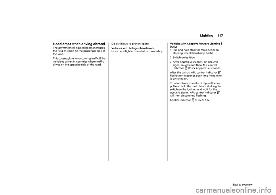
Headlamps when driving abroad The asymmetrical dipped beam increases
the field of vision on the passenger side of
the lane.
This causes glare for oncoming traffic if the
vehicle is driven in countries where traffic
drives on the opposite side of the road. Do as follows to prevent glare:
Vehicles with halogen headlamps
Have headlights conv
erted in a workshop. Vehicles with Adaptive Forward Lighting
3
(AFL)
1. Pull and hold stalk for main beam on steering wheel (headlamp flash).
2. Switch on ignition.
3. After approx. 3 seconds, an acoustic signal sounds and then AFL control
indicator
B flashes approx. 4 seconds.
After the switch, AFL control indicator
B
flashes for 4 seconds each time the ignition
is switched on.
To return to asymmetrical dipped beam,
pull and hold the main beam stalk again,
switch on the ignition and wait for the
acoustic signal. AFL control indicator
B
will then discontinue flashing.
Control indicator
B
3 85. 3112.
Back to overview
Page 124 of 284
118 Infotainment systemInfotainment system
Radio reception
3
Radio reception may be disrupted by
static, noise, distortion or loss of reception
due to
zchanges in dist ance from the
transmitter,
z multi-path reception due to reflection
and
z shadowing. Infotainment system
3
The infotainment system is operated as
described in the operating instructions.
Picture no: 18188s.tif
Steering wheel remote control
3
The functions of the Infotainment system 3
and the information display can be
operated with the adjusting wheels and
buttons on the steering wheel.
Further information 397 and the
infotainment system instructions.
Radio reception
3................................ 118
Infotainment system 3........................ 118
Steering wheel remote control 3........ 118
AUX input 3......................................... 119
Mobile telephones and radio equipment 3...................................... 119
Back to overview
Page 125 of 284

119
Infotainment system
Picture no: 18471s.tif
AUX input
3
The AUX input is in the centre console in
front of the gearshift lever.
An external audio source such as a
portable CD player can be connected via
the AUX input with a 3.5 mm jack plug.
Keep AUX input clean and dry at all times.
Further information in the infotainment
system instructions.
Mobile telephones and radio
equipment
3
The Opel installation instructions and the
operating guidelines provided by the
telephone manufacturer must be followed
when fitting and operating a mobile
telephone. Failure to do so could invalidate
the vehicle’s operating permit
(EU Directive 95 54/EG).
Recommended prerequisites for fault-free
operation:
z Professionally installed exterior antenna
to obtain the maximum range possible.
z Maximum transmission power 10 Watt.
z Installation of the te lephone in a suitable
spot (see information 377).
Seek advice on predetermined installation
points for the external antenna or
equipment holder and ways of using
devices with a transmission power
exceeding 10 watts.
We recommend you contact your Opel
Service Partner who will have brackets and
various different accessory kits available
and can fit them correctly. Use of a handsfree attachment without
external antenna with mobile telephone
standards GSM 900/1800/1900 and UMTS
is only permitted if the maximum
transmission power of the mobile
telephone is 2 watts for GSM 900 or 1 watt
for the other types.
For reasons of safety, we recommend that
you do not use the phone while driving.
Even use of a handsfree set can be a
distraction while
driving. Be sure to observe
any country-specific regulations.
9
Warning
Mobile phones that do not comply with
the above-mentioned mobile phone
standard and radio equipment must
only be operated using an antenna that
is attached to the exterior of the vehicle.
Caution
Mobile phones and radio equipment
may cause malfunctions in the vehicle
electronics if they are operated in the
vehicle without the external antenna
unless the above-mentioned regulations
are complied with.
Back to overview
Page 126 of 284

120 Climate controlClimate control
Picture no: 18203s.tif
Heating and ventilation system,
air conditioning system
3
Ventilation, heating and cooling 3 are
combined into one unit that is designed to
provide comfort regardless of the season,
weather or outside temperature.
When cooling 3 is activated, the air is
cooled and dried. The heating unit heats the air as required in
all operating modes depending on the
position of the temperature switch. The air
supply can be adjusted to suit
requirements by means of the fan.
Heating and ventilation system, air conditioning system 3...................... 120
Electronic climate control system 3... 121
Air vents ............................................... 122
Heating and ventilation system ......... 123
Air conditioning system 3................... 126
Electronic climate control system 3... 128
Auxiliary heater ................................... 134
Air intake .............................................. 135
Pollen filter ........................................... 135
Regular operation ............................... 135
Service .................................................. 135
Back to overview
Page 127 of 284
121
Climate control
Picture no: 18204s.tif
The buttons for cooling n and air
recirculation 4 are only found on
versions with optional air conditioning
system 3 .
Air conditioning system 3 3 126.
Picture no: 18205s.tif
Electronic climat e control system
3
Offers the greatest comfort in the vehicle
interior regardless of th e conditions outside.
To ensure a uniform and comfortable
climate in the vehicle, the temperature of
inflowing air, air-flow rate and air
distribution are automatically adapted
based on the climate conditions outside
the vehicle and the current temperature of
the vehicle interior. The set values appear on the information
display.
Electronic climate control system
3128.
Back to overview
Page 128 of 284

122 Climate control
Picture no: 18304s.tif
Air vents At least one air vent must be open while
cooling 3 (air conditioning compressor) is
on in order to prevent the evaporator from
icing up due to lack of air movement.
Comfortable ventilation of the interior is
based on the position of the temperature
switch.
To increase the air supply, set the fan to a
higher speed and set the air distribution
switch to M or L.
Picture no: 18305s.tif
Centre and side air vents (1)
Set the direction of the air flow by turning
the adjuster wheel from right to left and
raise or lower the horizontal slats.
The side air vents can be directed at the
door windows in order to assist the
windscreen defroster nozzles (2).
To close the air vent, turn the adjuster
wheel left or right to its stop. Windscreen defros
ter nozzles (2)
Air distribution switch set to l: Air is
directed onto the windscreen and the door
windows.
Other air vents
Located beneath the windscreen and in
the foot wells.
Back to overview