Page 3781 of 4331

MA-38< SERVICE INFORMATION >
CHASSIS AND BODY MAINTENANCE
CVT FLUID : Checking CVT Fluid (RE0F08A) INFOID:0000000004803426
FLUID LEVEL CHECK
Fluid level should be checked with the fluid warmed up to 50 ° to 80 °C (122 ° to 176 °F).
1. Check for fluid leakage.
2. With the engine warmed up, drive the vehicle to warm up the CVT fluid. When ambient temperature is 20 °C (68 °F), it takes
about 10 minutes for the CVT fluid to warm up to 50 ° to 80 °C
(122 ° to 176 °F).
3. Park the vehicle on a level surface and set the parking brake.
4. With engine at idle, while depressing brake pedal, move the selector lever throughout the entire shift range and return it to
the “P” position.
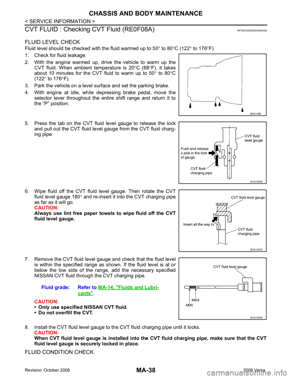
5. Press the tab on the CVT fluid level gauge to release the lock and pull out the CVT fluid level gauge from the CVT fluid charg-
ing pipe.
6. Wipe fluid off the CVT fluid level gauge. Then rotate the CVT fluid level gauge 180 ° and re-insert it into the CVT charging pipe
as far as it will go.
CAUTION:
Always use lint free paper towels to wipe fluid off the CVT
fluid level gauge.
7. Remove the CVT fluid level gauge and check that the fluid level is within the specified range as shown. If the fluid level is at or
below the low side of the range, add the necessary specified
NISSAN CVT fluid through the CVT charging pipe.
CAUTION:
• Only use specified NISSAN CVT fluid.
• Do not overfill the CVT.
8. Install the CVT fluid level gauge to the CVT fluid charging pipe until it locks. CAUTION:
When CVT fluid level gauge is in stalled into the CVT fluid charging pipe, make sure that the CVT
fluid level gauge is securely locked in place.
FLUID CONDITION CHECK SMA146B
SCIA1933E
SCIA1931E
Fluid grade: Refer to
MA-14, " Fluids and Lubri-
cants " .
SCIA1932E
Page 3783 of 4331

MA-40< SERVICE INFORMATION >
CHASSIS AND BODY MAINTENANCE
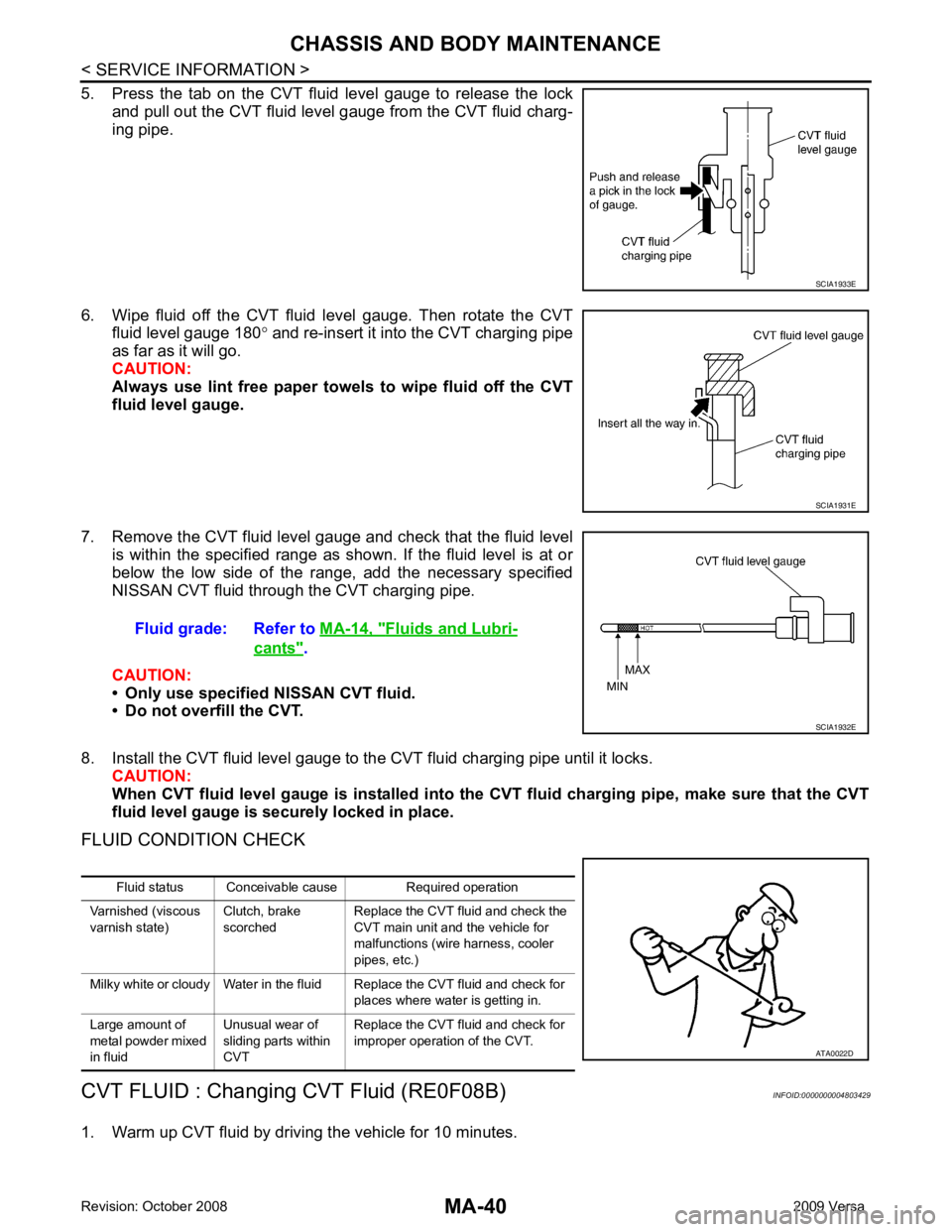
5. Press the tab on the CVT fluid level gauge to release the lock and pull out the CVT fluid level gauge from the CVT fluid charg-
ing pipe.
6. Wipe fluid off the CVT fluid level gauge. Then rotate the CVT fluid level gauge 180 ° and re-insert it into the CVT charging pipe
as far as it will go.
CAUTION:
Always use lint free paper towels to wipe fluid off the CVT
fluid level gauge.
7. Remove the CVT fluid level gauge and check that the fluid level is within the specified range as shown. If the fluid level is at or
below the low side of the range, add the necessary specified
NISSAN CVT fluid through the CVT charging pipe.
CAUTION:
• Only use specified NISSAN CVT fluid.
• Do not overfill the CVT.
8. Install the CVT fluid level gauge to the CVT fluid charging pipe until it locks. CAUTION:
When CVT fluid level gauge is in stalled into the CVT fluid charging pipe, make sure that the CVT
fluid level gauge is securely locked in place.
FLUID CONDITION CHECK
CVT FLUID : Changing CVT Fluid (RE0F08B) INFOID:0000000004803429
1. Warm up CVT fluid by driving the vehicle for 10 minutes. SCIA1933E
SCIA1931E
Fluid grade: Refer to
MA-14, " Fluids and Lubri-
cants " .
SCIA1932E
Fluid status Conceivable cause Required operation
Varnished (viscous
varnish state) Clutch, brake
scorched Replace the CVT fluid and check the
CVT main unit and the vehicle for
malfunctions (wire harness, cooler
pipes, etc.)
Milky white or cloudy Water in the fluid Replace the CVT fluid and check for places where water is getting in.
Large amount of
metal powder mixed
in fluid Unusual wear of
sliding parts within
CVT Replace the CVT fluid and check for
improper operation of the CVT. ATA0022D
Page 3784 of 4331
![NISSAN TIIDA 2009 Service Repair Manual CHASSIS AND BODY MAINTENANCE
MA-41
< SERVICE INFORMATION >
C
D E
F
G H
I
J
K
M A
B MA
N
O P
• : Vehicle front
• Radiator (2)
• CVT fluid cooler hose [inlet side (3)]
• Transaxle assembly (4)
2 NISSAN TIIDA 2009 Service Repair Manual CHASSIS AND BODY MAINTENANCE
MA-41
< SERVICE INFORMATION >
C
D E
F
G H
I
J
K
M A
B MA
N
O P
• : Vehicle front
• Radiator (2)
• CVT fluid cooler hose [inlet side (3)]
• Transaxle assembly (4)
2](/manual-img/5/57398/w960_57398-3783.png)
CHASSIS AND BODY MAINTENANCE
MA-41
< SERVICE INFORMATION >
C
D E
F
G H
I
J
K
M A
B MA
N
O P
• : Vehicle front
• Radiator (2)
• CVT fluid cooler hose [inlet side (3)]
• Transaxle assembly (4)
2. Drain CVT fluid from CVT fluid cooler hose [outlet side (1)] and refill with new specified NISSAN CVT fluid in the CVT fluid
charging pipe with the engine running at idle speed.
CAUTION:
Only use the specifi ed NISSAN CVT fluid.
3. Refill until new CVT fluid comes out from CVT fluid cooler hose [outlet side (1)]. NOTE:
About 30 to 50% extra fluid will be required for this procedure.
4. Check fluid level and condition. Refer to MA-39, " CVT FLUID : Checking CVT Fluid (RE0F08B) " .
CAUTION:
Delete CVT fluid deterioration date with CO NSULT-III after changing CVT fluid. Refer to CVT-230," CONSULT-III Function (TRANSMISSION) " .
CLUTCH FLUID
CLUTCH FLUID : Air Bleeding Procedure INFOID:0000000004683730
CAUTION:
Do not spill clutch fluid onto painted surfaces. If it spills, wipe up immediately and wash the affected
area with water.
NOTE:
• Do not use a vacuum assist or any other type of pow er bleeder on this system. Use of a vacuum assist or
power bleeder will not purge all the air from the system.
• Carefully monitor fluid level in reservoir tank during bleeding operation.
1. Fill master cylinder reservoir tank with new clutch fluid.
2. Connect a transparent vinyl tube and container to the bleeding connector (1) on the CSC.
3. Depress and release the clutch pedal slowly and fully 15 times at an interval of two to three seconds and release the clutch
pedal.
4. Push in the lock pin (1) of the bleeding connector (2), and maintain the position. • RS5F91R transaxle models
CAUTION:
Hold the lock pin in to preven t the bleeding connector from
separating when fluid pressure is applied.
Fluid capacity and grade: Refer to
MA-14, " Fluids
and Lubricants " .
SCIA6088E
PCIB1494E
PCIB1495E
Page 3792 of 4331
MA
N
O P
DRIVE SHAFT
DRIVE SHAFT : Drive Shaft INFOID:0000000004305218
Check boot and drive shaft for cracks, wear, damage and grease
leakage.
LOCKS, HINGES AND HOOD LATCH SDIA1190J
Page 3815 of 4331
MT
N
O P
Final Drive Component 1. Retaining pin 2. 1st-2nd shift fork 3. Bushing
4. 1st-2nd fork rod 5. Lock pin 6. 5th-reverse fork rod
7. 5th-reverse shift fork 8. Check ball 9. 3rd-4th shift fork
10. 3rd-4th fork rod 11. Control shaft 12. O-ring
13. Selector 14. Check ball plug 15. Bushing
16. Spring 17. Gear catch
: Apply gear oil.
: Apply Genuine Si licone RTV or an equivalent. Refer to XX-XX, "*****".
: Replace the parts as a set.
Page 3825 of 4331
![NISSAN TIIDA 2009 Service Repair Manual TRANSAXLE ASSEMBLY
MT-31
< SERVICE INFORMATION >
[RS5F91R] D
E
F
G H
I
J
K L
M A
B MT
N
O P
24. Install lock pins ( ) to clutch housing.
25. Install 3rd-4th shift fork to 3rd-4th fork rod, and NISSAN TIIDA 2009 Service Repair Manual TRANSAXLE ASSEMBLY
MT-31
< SERVICE INFORMATION >
[RS5F91R] D
E
F
G H
I
J
K L
M A
B MT
N
O P
24. Install lock pins ( ) to clutch housing.
25. Install 3rd-4th shift fork to 3rd-4th fork rod, and](/manual-img/5/57398/w960_57398-3824.png)
TRANSAXLE ASSEMBLY
MT-31
< SERVICE INFORMATION >
[RS5F91R] D
E
F
G H
I
J
K L
M A
B MT
N
O P
24. Install lock pins ( ) to clutch housing.
25. Install 3rd-4th shift fork to 3rd-4th fork rod, and then install retaining pin to 3rd-4th shift fork.
CAUTION:
• Never reuse retaining pin.
• Replace 3rd-4th fork rod and 3rd-4th shift fork as a set.
26. Install 3rd-4th fork rod assembly (1), 3rd-4th coupling sleeve (2), and input shaft assembly (3) to clutch housing according to the
following procedures.
a. Pull 1st-2nd fork rod (4) up, and then maintain the neutral posi- tion.
b. Set 3rd-4th fork rod assembly onto 3rd-4th coupling sleeve, and then install them together with input shaft assembly to clutch
housing.
CAUTION:
• Set lock pin (3rd-4th fork rod side) onto 1st-2nd fork rod groove and then install 3rd-4th fork rod assembly.
• Be careful with the orientat ion of 3rd-4th coupling sleeve.
- A: 4th main gear side
- B: 3rd main gear side
• Install 3rd input gear of in put shaft assembly so that it is
set under reverse main gear of 3rd-4th coupling sleeve.
• Replace 3rd-4th coupling sl eeve and 3rd-4th synchronizer
hub as a set.
c. Install springs and insert keys to 3rd-4th synchronizer hub.
d. Apply gear oil to 4th baulk ring.
e. Install 4th baulk ring.
27. Install 5th-reverse fork rod (1) to clutch housing according to the following procedures.
CAUTION:
Replace 5th-reverse fork rod and 5th-reverse shift fork as a
set.
a. Pull gear of reverse gear assembly (2) up.
b. Temporarily install 5th-reverse fork rod to clutch housing. JPDIC0534ZZ
PCIB1628E
PCIB1551E
MCIB0061E
PCIB1629E
Page 3826 of 4331
Rec-
ommended Chemical Product and Sealant " .
CAUTION:
• Never allow old liquid gasket, moisture, oil, or foreign matter to remain on mounting surface.
• Check that mounting surface is not damaged.
• Apply a continuous bead of liqu id gasket to the mounting surface.
32. Install transaxle case to clutch housing. If it is difficult to install, slightly rotate control shaft shift lever counterclockwise, and then
install.
• 1: Selector
• 2: Shift fork
CAUTION:
• Never disrupt liquid gasket bead with transaxle case or
other objects during installation.
• Be careful to align the lever of 5th-reverse fork rod with
reverse gear assembly groove. PCIB1529E
PCIB1524E
PCIB1553E
Page 3849 of 4331
MT
N
O P
CONTROL LINKAGE
Component of Contro l Device and Cable INFOID:0000000004305275
Removal and Installation INFOID:0000000004305276
REMOVAL 1. Remove battery. Refer to SC-7, " Removal and Installation " .
2. Remove air duct (front), air duct (Inlet) and air cleaner case. Refer to EM-139, " Removal and Installation " .
3. Remove shift cable from shift lever.
4. Remove select cable according to the following.
a. Move stopper (1) to the unlocked position. 1. Control lever knob 2. Control lever 3. Control device assembly
4. Select cable 5. Shift cable 6. Lock plate
7. Clutch housing 8. Cable bracket 9. Tapping bolt
10. Cable support bracket 11. Adapter plate SCIA7842E