Page 3947 of 4331
Component Parts " .
2. Remove side ventilator duct (right). Refer to MTC-69, " Removal and Installation " .
3. Disconnect blower motor connector (1).
4. Push the flange holding hook (A) toward the blower motor (2), then rotate the blower motor (2) clockwise and remove it from
the A/C unit assembly.
CAUTION:
When blower fan and blower motor are assembled, the bal-
ance is adjusted, do not di sassemble to replace the individ-
ual parts.
INSTALLATION
Installation is in the reverse order of removal.
CAUTION:
Rotate the blower motor until the blower motor fl ange holding hook locks securely into the A/C unit
assembly.
Page 3953 of 4331

MTC-68< SERVICE INFORMATION >
AIR CONDITIONER FILTER
AIR CONDITIONER FILTER
Removal and Installation INFOID:0000000004307087
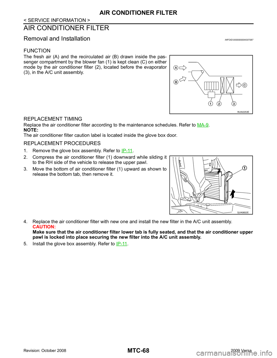
FUNCTION
The fresh air (A) and the recirculated air (B) drawn inside the pas-
senger compartment by the blower fan (1) is kept clean (C) on either
mode by the air conditioner filter (2), located before the evaporator
(3), in the A/C unit assembly.
REPLACEMENT TIMING
Replace the air conditioner filter accord ing to the maintenance schedules. Refer to MA-9 .
NOTE:
The air conditioner filter caution label is located inside the glove box door.
REPLACEMENT PROCEDURES
1. Remove the glove box assembly. Refer to IP-11 .
2. Compress the air conditioner filter (1) downward while sliding it to the RH side of the vehicle to release the upper pawl.
3. Move the bottom of air conditioner filter (1) upward as shown to release the bottom tab, then remove it.
4. Replace the air conditioner filter with new one and install the new filter in the A/C unit assembly. CAUTION:
Make sure that the air conditioner filter lower tab is fully seated, and that the air conditioner upper
pawl is locked into place securing the ne w filter into the A/C unit assembly.
5. Install the glove box assembly. Refer to IP-11 . WJIA2253E
SJIA0652E
Page 3978 of 4331
PB
N
O P
5. When the repair work is completed, return the ignition switch to the
″LOCK ″ position before connecting
the battery cables. (At this time, the steering lock mechanism will engage.)
6. Perform a self-diagnosis check of al l control units using CONSULT-III.
Page 3984 of 4331

PG
N
O P
CONTENTS
POWER SUPPLY, GROUND & CIRCUIT ELEMENTS
SERVICE INFORMATION .. ..........................2
PRECAUTIONS .............................................. .....2
Precaution for Supplemental Restraint System
(SRS) "AIR BAG" and "SEAT BELT PRE-TEN-
SIONER" ............................................................. ......
2
POWER SUPPLY ROUTING CIRCUIT .......... .....3
Schematic ........................................................... ......3
Wiring Diagram - POWER - ................................ ......5
Fuse .................................................................... ....15
Fusible Link ......................................................... ....15
Circuit Breaker (Built Into BCM) .......................... ....15
Circuit Breaker .................................................... ....15
IPDM E/R (INTELLIGENT POWER DISTRI-
BUTION MODULE ENGINE ROOM) ............. ....16
System Description ............................................. ....16
CAN Communication System Description ........... ....17
Function of Detecting Igni tion Relay Malfunction ....17
CONSULT-III Function (IPDM E/R) ..................... ....17
Auto Active Test .................................................. ....19
IPDM E/R Terminal Arrangement - Type A ......... ....22
IPDM E/R Terminal Arrangement - Type B ......... ....23
Terminal and Reference Value for IPDM E/R ..... ....24
IPDM E/R Power/Ground Circuit Inspection ....... ....26
Inspection with CONSULT- III (Self-Diagnosis) .......27
Removal and Installation of IPDM E/R ....................27 GROUND CIRCUI
T ........................................... 29
Ground Distribution .............................................. ....29
HARNESS ................... ...................................... 38
Harness Layout ................................................... ....38
Wiring Diagram Codes (Cell Codes) ................... ....57
ELECTRICAL UNITS LOCATION .................... 60
Electrical Units Location ...................................... ....60
HARNESS CONNECTOR ................................. 64
Description ........................................................... ....64
ELECTRICAL UNITS ........................................ 67
Terminal Arrangement ......................................... ....67
STANDARDIZED RELAY ................................. 68
Description ........................................................... ....68
SUPER MULTIPLE JUNCTION (SMJ) ............. 70
Terminal Arrangement ......................................... ....70
FUSE BLOCK-JUNCTION BOX (J/B) .............. 72
Terminal Arrangement ......................................... ....72
FUSE AND FUSIBLE LINK BOX ...................... 73
Terminal Arrangement ......................................... ....73
Page 4001 of 4331

Item name
CONSULT-III
screen display Display or unit Monitor item selection
Description
ALL
SIGNALS MAIN
SIGNALS SELECTION
FROM MENU
Motor fan request MOTOR FAN
REQ 1/2/3/4 X X X Signal status input from ECM
Compressor re-
quest AC COMP REQ ON/OFF X X X Signal status input from ECM
Parking, license,
and tail lamp re-
quest TAIL & CLR REQ ON/OFF X X X Signal status input from BCM
Headlamp low
beam request HL LO REQ ON/OFF X X X Signal status input from BCM
Headlamp high
beam request HL HI REQ ON/OFF X X X Signal
status input from BCM
Front fog request FR FOG REQ ON/OFF X X X Signal status input from BCM
FR wiper request FR WIP REQ STOP/1LO/LO/HI X X X Signal status input from BCM
Wiper auto stop WIP AUTO
STOP ACT P/STOP P X X X Output status of IPDM E/R
Wiper protection WIP PROT OFF/LS/HS/Block X X X Control status of IPDM E/R
Starter request ST RLY REQ ON/OFF X X Status of input signal (*1)
Ignition relay
status IGN RLY ON/OFF X X X Ignition relay status monitored
with IPDM E/R
Rear defogger re-
quest RR DEF REQ ON/OFF X X X Signal status input from BCM
Oil pressure
switch OIL P SW OPEN/CLOSE X X
Signal status input from IPDM
E/R
Hood switch HOOD SW (*2) OFF X X Signal status input from IPDM
E/R
Page 4008 of 4331

PG
N
O P
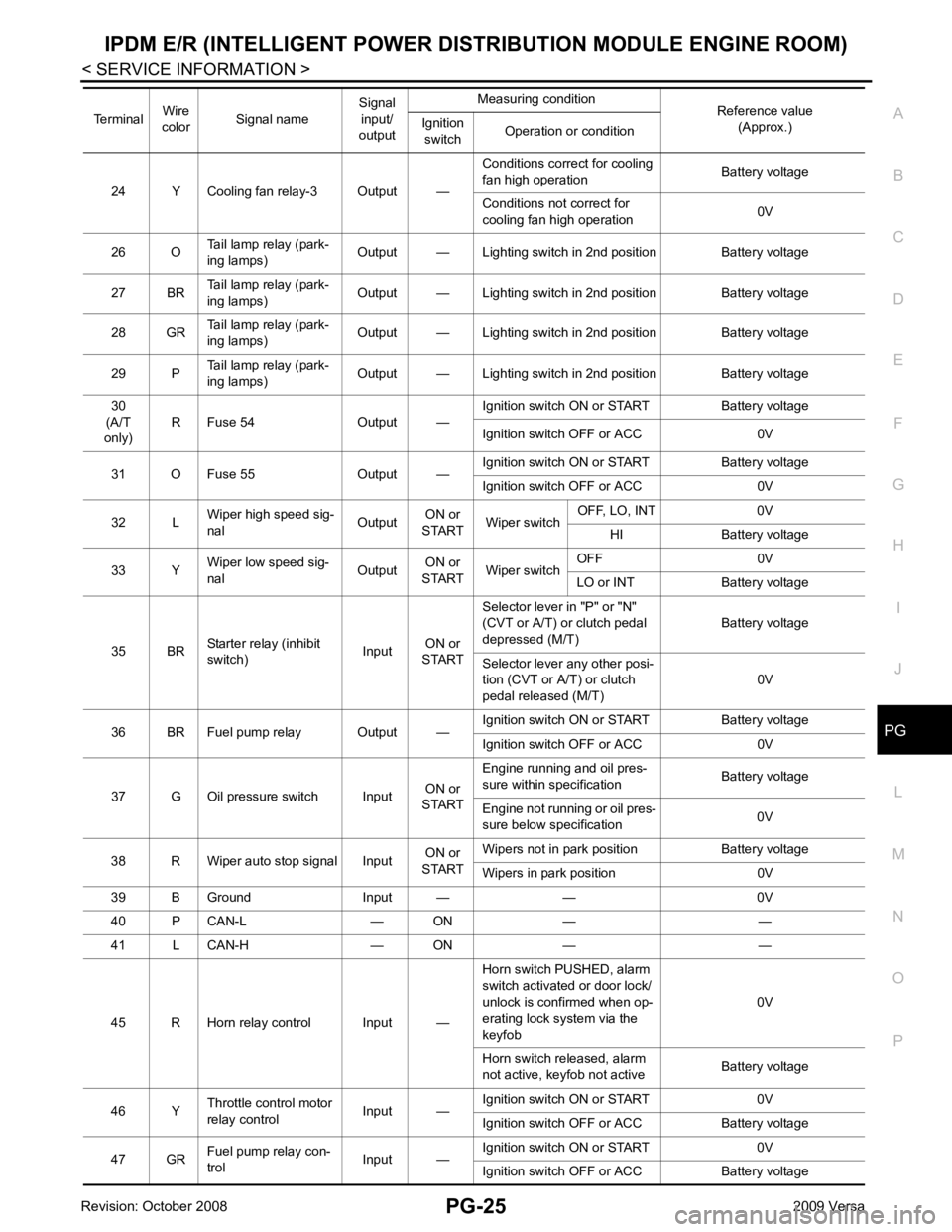
24 Y Cooling fan relay-3 Output —
Conditions correct for cooling
fan high operation Battery voltage
Conditions not correct for
cooling fan high operation 0V
26 O Tail lamp relay (park-
ing lamps) Output — Lighting switch in 2nd position Battery voltage
27 BR Tail lamp relay (park-
ing lamps) Output — Lighting switch in 2nd position Battery voltage
28 GR Tail lamp relay (park-
ing lamps) Output — Lighting switch in 2nd position Battery voltage
29 P Tail lamp relay (park-
ing lamps) Output — Lighting switch in 2nd position Battery voltage
30
(A/T
only) R Fuse 54 Output — Ignition switch ON or START Battery voltage
Ignition switch OFF or ACC 0V
31 O Fuse 55 Output — Ignition switch ON or START Battery voltage
Ignition switch OFF or ACC 0V
32 L Wiper high speed sig-
nal OutputON or
START Wiper switch OFF, LO, INT 0V
HI Battery voltage
33 Y Wiper low speed sig-
nal OutputON or
START Wiper switch OFF 0V
LO or INT Battery voltage
35 BR Starter relay (inhibit
switch) InputON or
START Selector lever in "P" or "N"
(CVT or A/T) or clutch pedal
depressed (M/T) Battery voltage
Selector lever any other posi-
tion (CVT or A/T) or clutch
pedal released (M/T) 0V
36 BR Fuel pump relay Output — Ignition switch ON or START Battery voltage
Ignition switch OFF or ACC 0V
37 G Oil pressure switch Input ON or
START Engine running and oil pres-
sure within specification Battery voltage
Engine not running or oil pres-
sure below specification 0V
38 R Wiper auto stop signal Input ON or
START Wipers not in park position Battery voltage
Wipers in park position 0V
39 B Ground Input — — 0V
40 P CAN-L — ON — —
41 L CAN-H — ON — —
45 R Horn relay control Input — Horn switch PUSHED, alarm
switch activated or door lock/
unlock is confirmed when op-
erating lock system via the
keyfob 0V
Horn switch released, alarm
not active, keyfob not active Battery voltage
46 Y Throttle control motor
relay control Input —Ignition switch ON or START 0V
Ignition switch OFF or ACC Battery voltage
47 GR Fuel pump relay con-
trol Input —Ignition switch ON or START 0V
Ignition switch OFF or ACC Battery voltage
Terminal
Wire
color Signal name Signal
input/
output Measuring condition
Reference value
(Approx.)
Ignition
switch Operation or condition
Page 4035 of 4331
D1 W/16 : To M9 D7 W/16 : Main power window and door lock/unlock switch
D2 W/16 : To M8 D8 W/3 : Main power window and door lock/unlock switch
D3 B/6 : Front door lock actuator LH D9 B/6 : Front power window motor LH
D4 BR/8 : Door mirror LH D10 GR/2 : Front outside antenna LH
D5 GR/2 : Front door request switch LH D12 W/2 : Front door speaker LH
D6 BR/2 : Intelligent key warning buzzer (front door LH) D14 BR/3 : Front door key cylinder switch LH
Page 4040 of 4331

PG
N
O P
Wiring Diagram Codes (Cell Codes)
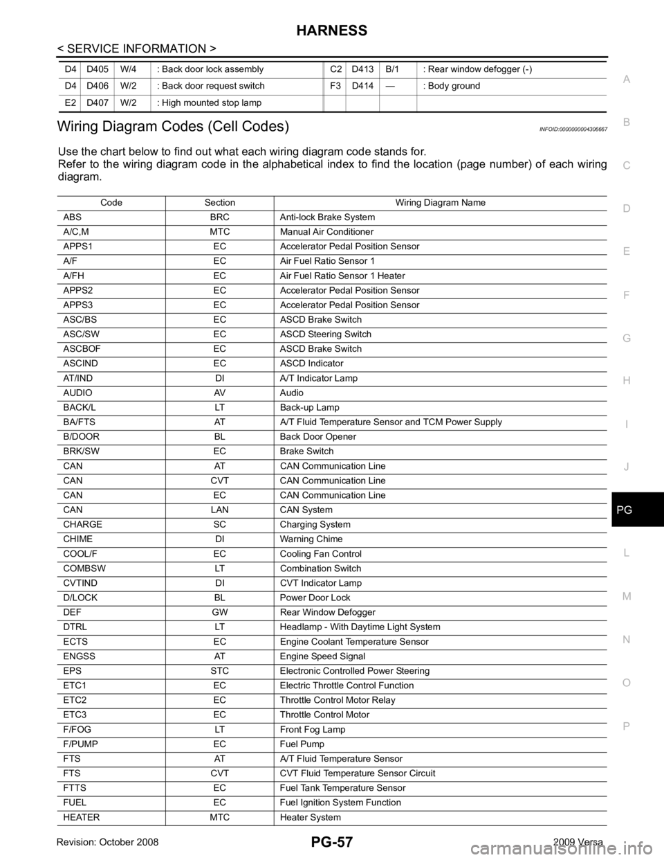
INFOID:0000000004306667
Use the chart below to find out what each wiring diagram code stands for.
Refer to the wiring diagram code in the alphabetical index to find the location (page number) of each wiring
diagram. D4 D405 W/4 : Back door lock assembly C2 D413 B/1 : Rear window defogger (-)
D4 D406 W/2 : Back door request switch F3 D414 — : Body ground
E2 D407 W/2 : High mounted stop lamp Code Section Wiring Diagram Name
ABS BRC Anti-lock Brake System
A/C,M MTC Manual Air Conditioner
APPS1 EC Accelerator Pe dal Position Sensor
A/F EC Air Fuel Ratio Sensor 1
A/FH EC Air Fuel Ratio Sensor 1 Heater
APPS2 EC Accelerator Pe dal Position Sensor
APPS3 EC Accelerator Pe dal Position Sensor
ASC/BS EC ASCD Brake Switch
ASC/SW EC ASCD Steering Switch
ASCBOF EC ASCD Brake Switch
ASCIND EC ASCD Indicator
AT/IND DI A/T Indicator Lamp
AUDIO AV Audio
BACK/L LT Back-up Lamp
BA/FTS AT A/T Fluid Temperature Sensor and TCM Power Supply
B/DOOR BL Back Door Opener
BRK/SW EC Brake Switch
CAN AT CAN Communication Line
CAN CVT CAN Comm unication Line
CAN EC CAN Communication Line
CAN LAN CAN System
CHARGE SC Charging System
CHIME DI Warning Chime
COOL/F EC Cooling Fan Control
COMBSW LT Combination Switch
CVTIND DI CVT Indicator Lamp
D/LOCK BL Power Door Lock
DEF GW Rear Window Defogger
DTRL LT Headlamp - Wi th Daytime Light System
ECTS EC Engine Coolant Temperature Sensor
ENGSS AT Engine Speed Signal
EPS STC Electronic Controlled Power Steering
ETC1 EC Electric Throttle Control Function
ETC2 EC Throttle Control Motor Relay
ETC3 EC Throttle Control Motor
F/FOG LT Front Fog Lamp
F/PUMP EC Fuel Pump
FTS AT A/T Fluid Temperature Sensor
FTS CVT CVT Fluid Temperature Sensor Circuit
FTTS EC Fuel Tank Temperature Sensor
FUEL EC Fuel Ignition System Function
HEATER MTC Heater System