Page 4182 of 4331
SE
N
O P
Assembly of Armrest
Assembly is in the reverse order of disassembly.
Disassembly of Seatback Trim and Pad 1. Remove the headrest.
2. Remove the retainer under the back of seatback.
3. Remove the clips, and then remove the striker cover.
4. Remove the headrest holder.
5. To remove armrest, refer to "Disassembly of Armrest " .
6. Remove the seatback trim.
7. Remove the bolts, and then remove the rear seat lock assembly.
8. Remove the seatback pad from the seatback frame.
9. Remove the seatback center bracket bolt and then remove the seatback frame. PIIB2485J
PIIB2487J
Page 4185 of 4331

SE-22< SERVICE INFORMATION >
REAR SEAT
Removal and Installation INFOID:0000000004306515
CAUTION:
When removing and in stalling, use shop cloths to protect parts from damage.
60:40 SPLIT FOLD DOWN SEAT - SEDAN
Removal
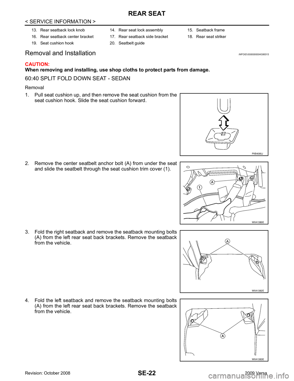
1. Pull seat cushion up, and then remove the seat cushion from the seat cushion hook. Slide the seat cushion forward.
2. Remove the center seatbelt anchor bolt (A) from under the seat and slide the seatbelt through the seat cushion trim cover (1).
3. Fold the right seatback and remove the seatback mounting bolts (A) from the left rear seat back brackets. Remove the seatback
from the vehicle.
4. Fold the left seatback and remove the seatback mounting bolts (A) from the left rear seat back brackets. Remove the seatback
from the vehicle.
13. Rear seatback lock knob 14. Rear seat lock assembly 15. Seatback frame
16. Rear seatback center bracket 17. Rear seatback side bracket 18. Rear seat striker
19. Seat cushion hook 20. Seatbelt guide PIIB4085J
WIIA1380E
WIIA1382E
WIIA1383E
Page 4186 of 4331

REAR SEAT
SE-23
< SERVICE INFORMATION >
C
D E
F
G H
J
K L
M A
B SE
N
O P
5. Remove the kicking plate rear inner. Refer to
EI-40, " Removal and Installation " .
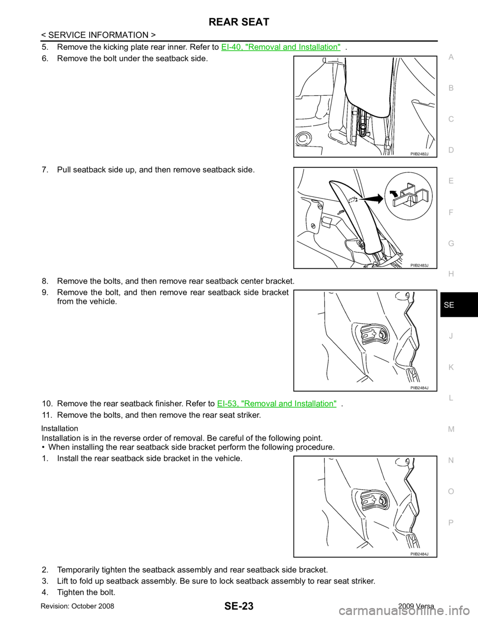
6. Remove the bolt under the seatback side.
7. Pull seatback side up, and then remove seatback side.
8. Remove the bolts, and then remove rear seatback center bracket.
9. Remove the bolt, and then remove rear seatback side bracket from the vehicle.
10. Remove the rear seatback finisher. Refer to EI-53, " Removal and Installation " .
11. Remove the bolts, and then remove the rear seat striker.
Installation Installation is in the reverse order of removal. Be careful of the following point.
• When installing the rear seatback side bracket perform the following procedure.
1. Install the rear seatback side bracket in the vehicle.
2. Temporarily tighten the seatback asse mbly and rear seatback side bracket.
3. Lift to fold up seatback assembly. Be sure to lock seatback assembly to rear seat striker.
4. Tighten the bolt. PIIB2482J
PIIB2483J
PIIB2484J
PIIB2484J
Page 4188 of 4331
REAR SEAT
SE-25
< SERVICE INFORMATION >
C
D E
F
G H
J
K L
M A
B SE
N
O P
Disassembly of Seatback Trim and Pad
1. Remove the headrest.
2. Remove the retainer under the back of seatback.
3. Remove the clips, and then remove the striker cover.
4. Remove the headrest holder.
5. To remove armrest, refer to "Disassembly of Armrest " .
6. Remove the seatback trim.
7. Remove the bolts, and then remove the rear seat lock assembly.
8. Remove the seatback pad from the seatback frame.
9. Remove the seatback center bracket bolt and then remove the seatback frame.
Assembly of Seatback Trim and Pad Assembly is in the reverse order of disassembly.
• Before installing headrest holder, check its orientation (front/rear and right/left). PIIB2486J
PIIB2485J
PIIB4084J
PIIB2487J
Page 4193 of 4331
SRS
N
O P
OPERATION PROCEDURE
1. Connect both battery cables. NOTE:
Supply power using jumper cables if battery is discharged.
2. Use the Intelligent Key or mechanical key to turn the ignition switch to the ″ACC ″ position. At this time, the
steering lock will be released.
3. Disconnect both battery cables. The steering lock will remain released and the steering wheel can be
rotated.
4. Perform the necessary repair operation.
5. When the repair work is completed, return the ignition switch to the ″LOCK ″ position before connecting
the battery cables. (At this time, the steering lock mechanism will engage.)
6. Perform a self-diagnosis check of al l control units using CONSULT-III.
Occupant Classification System Precaution INFOID:0000000004307174
Replace control unit and passenger front seat cushion as an assembly.
Page 4197 of 4331
SRS
N
O P
Direct-connect SRS Co
mponent Connectors INFOID:0000000004307182
The following SRS components use dire ct-connect style harness connectors.
• Driver air bag module
• Passenger air bag module
• LH side curtain air bag module
• RH side curtain air bag module
• Front LH seat belt pre-tensioner
• Front RH seat belt pre-tensioner
Always pull up to release the locking tab prior to removing connector from SRS component.
Always push down to lock the locking tab after installing connector to
SRS component. When locked, the locking tab is level with the con-
nector housing.
Page 4227 of 4331

SRS
N
O P
SPIRAL CABLE
Removal and Installation INFOID:0000000004307195
REMOVAL WARNING:
When servicing the SRS, do not work from directly in front of air bag module.
CAUTION:
• Before servicing the SRS, turn ignition switch OFF, disconnect both battery terminals and wait at
least three minutes.
• Do not tap or bump the steering wheel.
• Do not disassemble the spiral cable.
• Do not allow oil, grease or water to co me in contact with the spiral cable.
• Replace the spiral cable if it has b een dropped or sustained an impact.
• With the steering linkage disconn ected, the spiral cable may snap by turning the steering wheel
beyond the limited number of turns. The spiral cable can be turned counterclockwise about 2.5 turns
from the neutral position.
1. Disconnect the negative and positive battery term inals, then wait at least three minutes.
2. Set the front wheels to the straight-ahead/neutral position.
3. Remove the steering wheel. Refer to PS-6 .
4. Remove the column cover upper and lower.
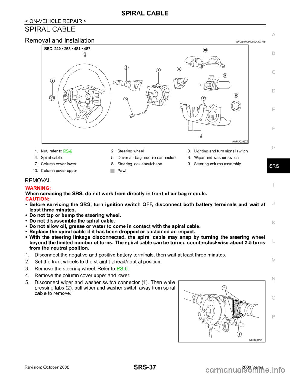
5. Disconnect wiper and washer switch connector (1). Then while pressing tabs (2), pull wiper and washer switch away from spiral
cable to remove. 2. Steering wheel 3. Lighting and turn signal switch
4. Spiral cable 5. Driver air bag module connectors 6. Wiper and washer switch
7. Column cover lower 8. Steering lock escutcheon 9. Steering column assembly
10. Column cover upper Pawl
Page 4243 of 4331
![NISSAN TIIDA 2009 Service Repair Manual PRECAUTIONS
STC-3
< SERVICE INFORMATION >
[EPS] C
D E
F
H I
J
K L
M A
B STC
N
O
P
5. When the repair work is completed, return the ignition switch to the
″LOCK ″ position before con NISSAN TIIDA 2009 Service Repair Manual PRECAUTIONS
STC-3
< SERVICE INFORMATION >
[EPS] C
D E
F
H I
J
K L
M A
B STC
N
O
P
5. When the repair work is completed, return the ignition switch to the
″LOCK ″ position before con](/manual-img/5/57398/w960_57398-4242.png)
PRECAUTIONS
STC-3
< SERVICE INFORMATION >
[EPS] C
D E
F
H I
J
K L
M A
B STC
N
O
P
5. When the repair work is completed, return the ignition switch to the
″LOCK ″ position before connecting
the battery cables. (At this time, the steering lock mechanism will engage.)
6. Perform a self-diagnosis check of al l control units using CONSULT-III.
Service Notice or Precaution for EPS System INFOID:0000000004307286
CAUTION:
Check or confirm the following item wh en performing the trouble diagnosis.
• Check any possible causes by interviewing the symptom and it’s condition from the customer if any
malfunction, such as EPS warn ing lamp turns ON, occurs.
• Check if air pressure and size of tires are proper, the specified part is used for the steering wheel,
and control unit is genuine part.
• Check if the connection of steer ing column assembly and steering gear assembly is proper (there is
not looseness of mounting bolts, damage of rods, boots or sealants, and leakage of grease, etc).
• Check if the wheel alignmen t is adjusted properly.
• Check if there is any damage or modification to su spension or body resulting in increased weight or
altered ground clearance.
• Check if installation conditions of each link and suspension are proper.
• Check if the battery voltage is proper
• Check connection conditions of each connector are proper.
• Before connecting or disconnect ing the EPS control unit har-
ness connector, turn ignition switch “OFF” and disconnect
battery ground cable. Because battery voltage is applied to
EPS control unit even if igniti on switch is turned “OFF”.
• When connecting or disconnect ing pin connectors into or
from EPS control unit, take care not to damage pin terminals
(bend or break).
When connecting pin connectors, make sure that there are no
bends or breaks on EPS control unit pin terminal.
• Before replacing EPS control unit, perform EPS control unit input/output signal inspectio n and make sure whether EPS
control unit functions properly or not. Refer to STC-9, " EPS
Control Unit Input/Output Signal Reference Value " . SEF289H
SEF291H
SDIA1848E