2009 NISSAN TIIDA brake sensor
[x] Cancel search: brake sensorPage 641 of 4331
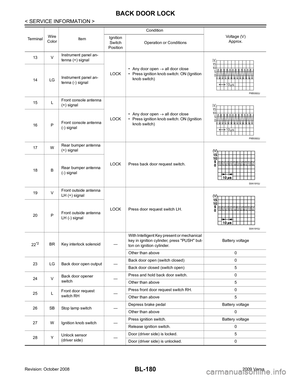
BL-180< SERVICE INFORMATION >
BACK DOOR LOCK
13 V Instrument panel an-
tenna (+) signal
LOCK• Any door open
→ all door close
• Press ignition knob switch: ON (Ignition knob switch)
14 LG Instrument panel an-
tenna (-) signal
15 L Front console antenna
(+) signal
LOCK• Any door open
→ all door close
• Press ignition knob switch: ON (Ignition knob switch)
16 P Front console antenna
(-) signal
17 W Rear bumper antenna
(+) signal
LOCK Press back door request switch.
18 B Rear bumper antenna
(-) signal
19 V Front outside antenna
LH (+) signal
LOCK Press door request switch LH.
20 P Front outside antenna
LH (-) signal
22 *2
BR Key interlock solenoid — With Intelligent Key present or mechanical
key in ignition cylinder, press "PUSH" but-
ton on ignition cylinder. Battery voltage
Other than above 0
23 LG Back door open output — Back door open (switch closed) 0
Back door closed (switch open) 5
24 V Back door opener
switch —Press and hold back door switch. 0
Other than above 5
25 L Front door request
switch RH —Press front door request switch RH. 0
Other than above 5
26 SB Stop lamp switch — Depress brake pedal Battery voltage
Other than above 0
27 W Ignition knob switch — Press ignition switch. Battery voltage
Release ignition switch. 0
28 Y Unlock sensor
(driver side) —Door (driver si
de) is locked. 5
Door (driver side ) is unlocked. 0
Terminal
Wire
Color Item Condition
Voltage (V)Approx.
Ignition
Switch
Position Operation or Conditions PIIB5502J
PIIB5502J
SIIA1910J
SIIA1910J
Page 665 of 4331
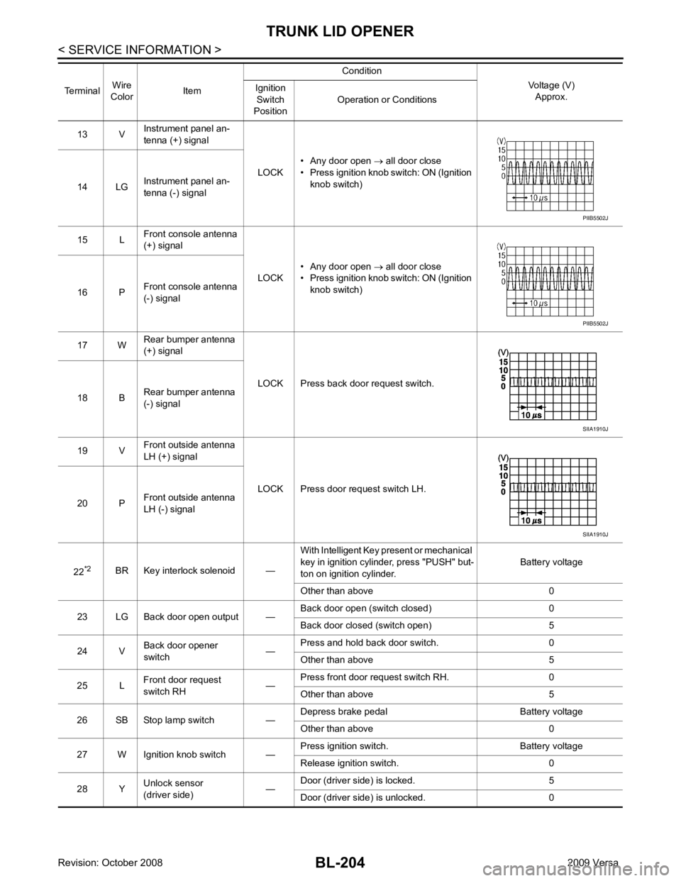
BL-204< SERVICE INFORMATION >
TRUNK LID OPENER
13 V Instrument panel an-
tenna (+) signal
LOCK• Any door open
→ all door close
• Press ignition knob switch: ON (Ignition knob switch)
14 LG Instrument panel an-
tenna (-) signal
15 L Front console antenna
(+) signal
LOCK• Any door open
→ all door close
• Press ignition knob switch: ON (Ignition knob switch)
16 P Front console antenna
(-) signal
17 W Rear bumper antenna
(+) signal
LOCK Press back door request switch.
18 B Rear bumper antenna
(-) signal
19 V Front outside antenna
LH (+) signal
LOCK Press door request switch LH.
20 P Front outside antenna
LH (-) signal
22 *2
BR Key interlock solenoid — With Intelligent Key present or mechanical
key in ignition cylinder, press "PUSH" but-
ton on ignition cylinder. Battery voltage
Other than above 0
23 LG Back door open output — Back door open (switch closed) 0
Back door closed (switch open) 5
24 V Back door opener
switch —Press and hold back door switch. 0
Other than above 5
25 L Front door request
switch RH —Press front door request switch RH. 0
Other than above 5
26 SB Stop lamp switch — Depress brake pedal Battery voltage
Other than above 0
27 W Ignition knob switch — Press ignition switch. Battery voltage
Release ignition switch. 0
28 Y Unlock sensor
(driver side) —Door (driver si
de) is locked. 5
Door (driver side ) is unlocked. 0
Terminal
Wire
Color Item Condition
Voltage (V)Approx.
Ignition
Switch
Position Operation or Conditions PIIB5502J
PIIB5502J
SIIA1910J
SIIA1910J
Page 693 of 4331
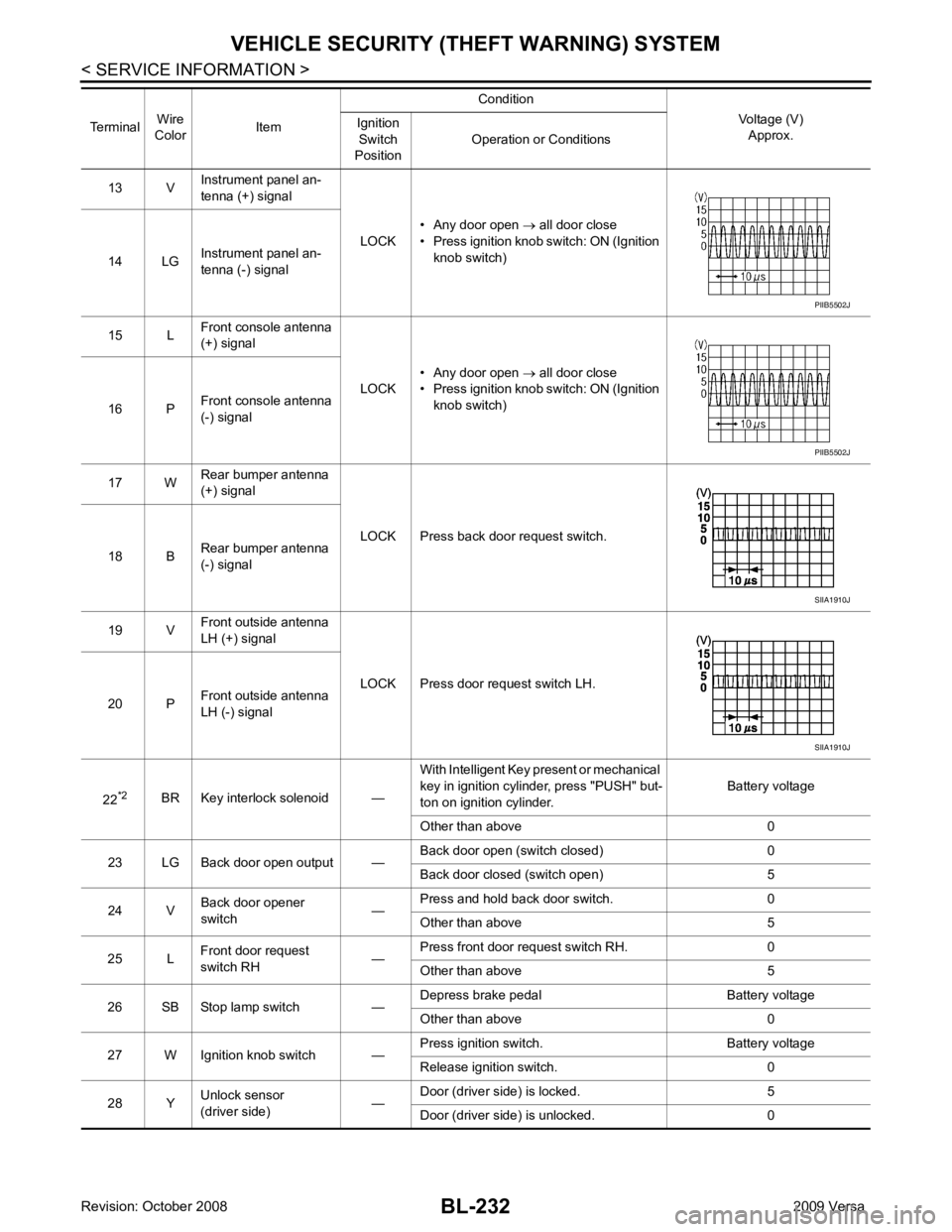
BL-232< SERVICE INFORMATION >
VEHICLE SECURITY (T
HEFT WARNING) SYSTEM
13 V Instrument panel an-
tenna (+) signal
LOCK• Any door open
→ all door close
• Press ignition knob switch: ON (Ignition knob switch)
14 LG Instrument panel an-
tenna (-) signal
15 L Front console antenna
(+) signal
LOCK• Any door open
→ all door close
• Press ignition knob switch: ON (Ignition knob switch)
16 P Front console antenna
(-) signal
17 W Rear bumper antenna
(+) signal
LOCK Press back door request switch.
18 B Rear bumper antenna
(-) signal
19 V Front outside antenna
LH (+) signal
LOCK Press door request switch LH.
20 P Front outside antenna
LH (-) signal
22 *2
BR Key interlock solenoid — With Intelligent Key present or mechanical
key in ignition cylinder, press "PUSH" but-
ton on ignition cylinder. Battery voltage
Other than above 0
23 LG Back door open output — Back door open (switch closed) 0
Back door closed (switch open) 5
24 V Back door opener
switch —Press and hold back door switch. 0
Other than above 5
25 L Front door request
switch RH —Press front door request switch RH. 0
Other than above 5
26 SB Stop lamp switch — Depress brake pedal Battery voltage
Other than above 0
27 W Ignition knob switch — Press ignition switch. Battery voltage
Release ignition switch. 0
28 Y Unlock sensor
(driver side) —Door (driver si
de) is locked. 5
Door (driver side ) is unlocked. 0
Terminal
Wire
Color Item Condition
Voltage (V)Approx.
Ignition
Switch
Position Operation or Conditions PIIB5502J
PIIB5502J
SIIA1910J
SIIA1910J
Page 841 of 4331

BRC
N
O P
CONTENTS
BRAKE CONTROL SYSTEM
ABS
SERVICE INFORMATION .. ..........................
2
PRECAUTIONS .............................................. .....2
Precaution for Supplemental Restraint System
(SRS) "AIR BAG" and "SEAT BELT PRE-TEN-
SIONER" ............................................................. ......
2
Precaution for Brake System .............................. ......2
Precaution for Brake Cont rol .....................................3
Precaution for CAN System ................................ ......3
PREPARATION .............................................. .....4
Special Service Tool ........................................... ......4
Commercial Service Tool .................................... ......4
SYSTEM DESCRIPTION ................................ .....5
System Component ............................................. ......5
ABS Function ...................................................... ......5
EBD Function ...................................................... ......5
Fail-Safe Function ............................................... ......5
Hydraulic Circuit Diagram .........................................6
CAN COMMUNICATION ................................ .....7
System Description ............................................. ......7
TROUBLE DIAGNOSIS ................................. .....8
How to Perform Trouble Diagnosis for Quick and
Accurate Repair ........... .............................................
8
Component Parts and Harness Connector Loca-
tion ...................................................................... ....
11
Schematic ........................................................... ....12
Wiring Diagram - ABS - ... ........................................13 Basic Inspection ..................................................
....16
Warning Lamp and Indicator Timing .................... ....17
Control Unit Input/Output Signal Standard .......... ....17
CONSULT-III Function ( ABS) ..................................18
TROUBLE DIAGNOSIS FOR SELF-DIAG-
NOSTIC ITEMS ................................................. 24
Wheel Sensor System ......................................... ....24
ABS Control Unit Inspection ................................ ....25
Solenoid Valve System Inspection ...................... ....25
Actuator Motor, Motor Re lay, and Circuit Inspec-
tion ....................................................................... ....
26
ABS Control Unit Power and Ground Systems In-
spection ............................................................... ....
27
CAN Communication System Inspection ............. ....28
TROUBLE DIAGNOSES FOR SYMPTOMS ..... 29
ABS Works Frequently ........................................ ....29
Unexpected Pedal Action .................................... ....29
Long Stopping Distance ...................................... ....30
ABS Does Not Work ............................................ ....30
Pedal Vibration or ABS Op eration Noise .................30
WHEEL SENSORS ........................................... 32
Removal and Installation ..................................... ....32
SENSOR ROTOR .............................................. 34
Removal and Installation ..................................... ....34
ACTUATOR AND ELECTRIC UNIT (ASSEM-
BLY) .................................................................. 35
Removal and Installation ..................................... ....35
Page 842 of 4331
![NISSAN TIIDA 2009 Service Repair Manual BRC-2< SERVICE INFORMATION >
[ABS]
PRECAUTIONS
SERVICE INFORMATION
PRECAUTIONS
Precaution for Supplemental Restraint Syst em (SRS) "AIR BAG" and "SEAT BELT
PRE-TENSIONER" INFOID:0000000004784402
The NISSAN TIIDA 2009 Service Repair Manual BRC-2< SERVICE INFORMATION >
[ABS]
PRECAUTIONS
SERVICE INFORMATION
PRECAUTIONS
Precaution for Supplemental Restraint Syst em (SRS) "AIR BAG" and "SEAT BELT
PRE-TENSIONER" INFOID:0000000004784402
The](/manual-img/5/57398/w960_57398-841.png)
BRC-2< SERVICE INFORMATION >
[ABS]
PRECAUTIONS
SERVICE INFORMATION
PRECAUTIONS
Precaution for Supplemental Restraint Syst em (SRS) "AIR BAG" and "SEAT BELT
PRE-TENSIONER" INFOID:0000000004784402
The Supplemental Restraint System such as “A IR BAG” and “SEAT BELT PRE-TENSIONER”, used along
with a front seat belt, helps to reduce the risk or severi ty of injury to the driver and front passenger for certain
types of collision. This system includes seat belt switch inputs and dual stage front air bag modules. The SRS
system uses the seat belt switches to determine the front air bag deployment, and may only deploy one front
air bag, depending on the severity of a collision and w hether the front occupants are belted or unbelted.
Information necessary to service the system safely is included in the SRS and SB section of this Service Man-
ual.
WARNING:
• To avoid rendering the SRS inopera tive, which could increase the risk of personal injury or death in
the event of a collision which would result in air bag inflation, all maintenance must be performed by
an authorized NISS AN/INFINITI dealer.
• Improper maintenance, including incorrect removal and installation of the SRS can lead to personal
injury caused by unintent ional activation of the system. For re moval of Spiral Cable and Air Bag
Module, see the SRS section.
• Do not use electrical test equipmen t on any circuit related to the SRS unless instructed to in this
Service Manual. SRS wiring harn esses can be identified by yellow and/or orange harnesses or har-
ness connectors.
PRECAUTIONS WHEN USING POWER TOOLS (AIR OR ELECTRIC) AND HAMMERS
WARNING:
• When working near the Airbag Diagnosis Sensor Unit or other Airbag System sensors with the Igni-
tion ON or engine running, DO NOT use air or electri c power tools or strike near the sensor(s) with a
hammer. Heavy vibration could activate the sensor( s) and deploy the air bag(s), possibly causing
serious injury.
• When using air or electric power tools or hammers , always switch the Ignition OFF, disconnect the
battery, and wait at least 3 minu tes before performing any service.
Precaution for Brake System INFOID:0000000004307251
CAUTION:
• Refer to MA-14 for recommended brake fluid.
• Never reuse drained brake fluid.
• Be careful not to splash brake fluid on painted areas; it may cause paint damage. If brake fluid is
splashed on painted areas, wash it away with water immediately.
• To clean or wash all parts of master cylin der and disc brake caliper, use clean brake fluid.
• Never use mineral oils such as gasoline or kerosene. They will ruin rubber parts of the hydraulic sys-
tem.
• Use flare nut wrench when re moving and installing brake
tube.
• If a brake fluid leak is found, the part must be disassembled
without fail. Then it has to be replaced with a new one if a
defect exists.
• Turn the ignition switch OFF an d remove the connector of the
ABS actuator and electric unit (c ontrol unit) or the battery ter-
minal before performing the work.
• Always torque brake lines when installing.
• Burnish the brake contact surf aces after refinishing or replac-
ing rotors, after replacing pads, or if a soft pedal occurs at
very low mileage. Refer to BR-32, " Brake Burnishing Proce-
dure " .
WARNING:
• Clean brake pads and shoes with a waste cloth, then wipe with a dust collector. SBR686C
Page 858 of 4331
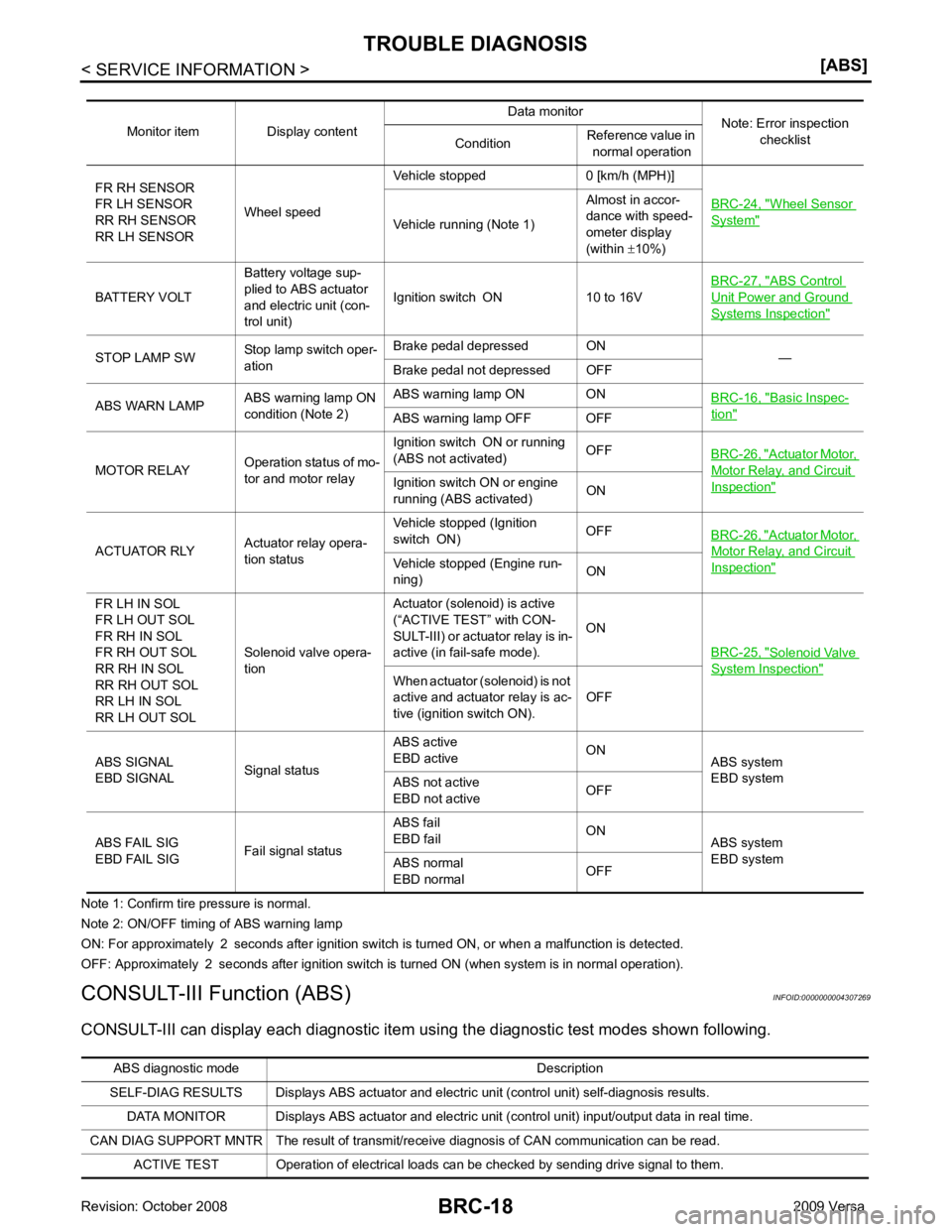
Wheel Sensor
System "
Vehicle running (Note 1)
Almost in accor-
dance with speed-
ometer display
(within ±10%)
BATTERY VOLT Battery voltage sup-
plied to ABS actuator
and electric unit (con-
trol unit) Ignition switch ON 10 to 16V
BRC-27, " ABS Control
Unit Power and Ground
Systems Inspection "
STOP LAMP SW
Stop lamp switch oper-
ation Brake pedal depressed ON
—
Brake pedal not depressed OFF
ABS WARN LAMP ABS warning lamp ON
condition (Note 2) ABS warning lamp ON ON
BRC-16, " Basic Inspec-
tion "
ABS warning lamp OFF OFF
MOTOR RELAY Operation status of mo-
tor and motor relay Ignition switch ON or running
(ABS not activated) OFF
BRC-26, " Actuator Motor,
Motor Relay, and Circuit
Inspection "Ignition switch ON or engine
running (ABS activated) ON
ACTUATOR RLY Actuator relay opera-
tion status Vehicle stopped (Ignition
switch ON) OFF
BRC-26, " Actuator Motor,
Motor Relay, and Circuit
Inspection "Vehicle stopped (Engine run-
ning) ON
FR LH IN SOL
FR LH OUT SOL
FR RH IN SOL
FR RH OUT SOL
RR RH IN SOL
RR RH OUT SOL
RR LH IN SOL
RR LH OUT SOL Solenoid valve opera-
tion Actuator (solenoid) is active
(“ACTIVE TEST” with CON-
SULT-III) or actuator relay is in-
active (in fail-safe mode). ON
BRC-25, " Solenoid Valve
System Inspection "
When actuator (solenoid) is not
active and actuator relay is ac-
tive (ignition switch ON). OFF
ABS SIGNAL
EBD SIGNAL Signal statusABS active
EBD active ON
ABS system
EBD system
ABS not active
EBD not active OFF
ABS FAIL SIG
EBD FAIL SIG Fail signal statusABS fail
EBD fail ON
ABS system
EBD system
ABS normal
EBD normal OFFABS diagnostic mo
de Description
SELF-DIAG RESULTS Displays ABS actuator and electric unit (control unit) self-diagnosis results.
DATA MONITOR Displays ABS actuator and electric unit (control unit) input/output data in real time.
CAN DIAG SUPPORT MNTR The result of transmit/receive diagnosis of CAN communication can be read. ACTIVE TEST Operation of electrical loads can be checked by sending drive signal to them.
Page 878 of 4331
CL-2< SERVICE INFORMATION >
PRECAUTIONS
SERVICE INFORMATION
PRECAUTIONS
Precaution for Supplemental Restraint Syst em (SRS) "AIR BAG" and "SEAT BELT
PRE-TENSIONER" INFOID:0000000004802358
The Supplemental Restraint System such as “A IR BAG” and “SEAT BELT PRE-TENSIONER”, used along
with a front seat belt, helps to reduce the risk or severi ty of injury to the driver and front passenger for certain
types of collision. This system includes seat belt switch inputs and dual stage front air bag modules. The SRS
system uses the seat belt switches to determine the front air bag deployment, and may only deploy one front
air bag, depending on the severity of a collision and w hether the front occupants are belted or unbelted.
Information necessary to service the system safely is included in the SRS and SB section of this Service Man-
ual.
WARNING:
• To avoid rendering the SRS inopera tive, which could increase the risk of personal injury or death in
the event of a collision which would result in air bag inflation, all maintenance must be performed by
an authorized NISS AN/INFINITI dealer.
• Improper maintenance, including incorrect removal and installation of the SRS can lead to personal
injury caused by unintent ional activation of the system. For re moval of Spiral Cable and Air Bag
Module, see the SRS section.
• Do not use electrical test equipmen t on any circuit related to the SRS unless instructed to in this
Service Manual. SRS wiring harn esses can be identified by yellow and/or orange harnesses or har-
ness connectors.
• When working near the Airbag Diagnosis Sensor Unit or other Airbag System sensors with the Igni-
tion ON or engine running, DO NOT use air or electri c power tools or strike near the sensor(s) with a
hammer. Heavy vibration could activate the sensor( s) and deploy the air bag(s), possibly causing
serious injury.
• When using air or electric power tools or hammers , always switch the Ignition OFF, disconnect the
battery, and wait at least 3 minu tes before performing any service.
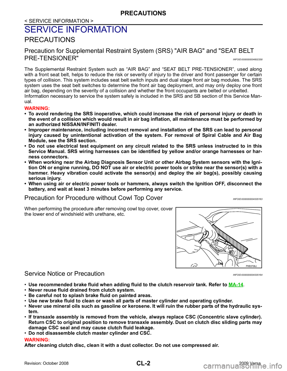
Precaution for Procedure without Cowl Top Cover INFOID:0000000004305163
When performing the procedure after removing cowl top cover, cover
the lower end of windshield with urethane, etc.
Service Notice or Precaution INFOID:0000000004305164
• Use recommended brake fluid when adding flui d to the clutch reservoir tank. Refer to MA-14 .
• Never reuse fluid drained from clutch system.
• Be careful not to splash brake fluid on painted areas.
• Use new brake fluid to clean or wash all part s of master cylinder and operating cylinder.
• Never use mineral oils such as gasoline or kerosene. It will ruin the rubber parts of the hydraulic sys-
tem.
• If transaxle assembly is removed from the vehicle , always replace CSC (Concentric slave cylinder).
Return CSC to original position to remove transaxle assembly. Dust on clutch disc sliding parts may
damage CSC seal and may cause clutch fluid leakage.
• Do not disassemble clutch master cylinder and CSC.
WARNING:
After cleaning clutch disc, clean it with a dust collector. Do not use compressed air. PIIB3706J
Page 951 of 4331

CVT
N
O
P
N
Description ..........................................................
..
293
CONSULT-III Refe rence Value in Data Monitor
Mode ................................................................... ..
293
On Board Diagnosis Logic .................................. ..293
Possible Cause ................................................... ..293
DTC Confirmation Procedure .............................. ..293
Diagnosis Procedure ........................................... ..293
DTC P1701 TRANSMISSION CONTROL
MODULE (POWER SUPPLY) ........................ ..295
Description .......................................................... ..295
On Board Diagnosis Logic .................................. ..295
Possible Cause ................................................... ..295
DTC Confirmation Procedure .............................. ..295
Wiring Diagram - CVT - POWER ........................ ..296
Diagnosis Procedure ........................................... ..297
DTC P1705 THROTTLE POSITION SENSOR ..299
Description .......................................................... ..299
CONSULT-III Refe rence Value in Data Monitor
Mode ................................................................... ..
299
On Board Diagnosis Logic .................................. ..299
Possible Cause ................................................... ..299
DTC Confirmation Procedure .............................. ..299
Diagnosis Procedure ........................................... ..299
DTC P1722 ESTM VEHICLE SPEED SIGNAL ..301
Description .......................................................... ..301
CONSULT-III Refe rence Value in Data Monitor
Mode ................................................................... ..
301
On Board Diagnosis Logic .................................. ..301
Possible Cause ................................................... ..301
DTC Confirmation Procedure .............................. ..301
Diagnosis Procedure ........................................... ..301
DTC P1723 CVT SPEED SENSOR FUNC-
TION ............................................................... ..303
Description .......................................................... ..303
On Board Diagnosis Logic .................................. ..303
Possible Cause ................................................... ..303
DTC Confirmation Procedure .............................. ..303
Diagnosis Procedure ........................................... ..303
DTC P1726 ELECTRIC THROTTLE CON-
TROL SYSTEM .............................................. ..
305
Description .......................................................... ..305
On Board Diagnosis Logic .................................. ..305
Possible Cause ................................................... ..305
DTC Confirmation Procedure .............................. ..305
Diagnosis Procedure ........................................... ..305
DTC P1740 LOCK-UP SELECT SOLENOID
VALVE CIRCUIT ............................................ ..
306
Description .......................................................... ..306
CONSULT-III Refe rence Value in Data Monitor
Mode ................................................................... ..
306
On Board Diagnosis Logic .................................. ..306
Possible Cause ................................................... ..306
DTC Confirmation Procedure .............................. ..306
Wiring Diagram - CVT - L/USSV ......................... ..307 Diagnosis Procedure ...........................................
..308
Component Inspection ......................................... ..309
DTC P1745 LINE PRESSURE CONTROL ..... 310
Description ........................................................... ..310
On Board Diagnosis Logic ................................... ..310
Possible Cause .................................................... ..310
DTC Confirmation Procedure .............................. ..310
Diagnosis Procedure ........................................... ..310
DTC P1777 STEP MOTOR - CIRCUIT ........... 311
Description ........................................................... ..311
CONSULT-III Reference Va lue in Data Monitor
Mode .................................................................... ..
311
On Board Diagnosis Logic ................................... ..311
Possible Cause .................................................... ..311
DTC Confirmation Procedure .............................. ..311
Wiring Diagram - CVT - STM ............................... ..312
Diagnosis Procedure ........................................... ..313
Component Inspection ......................................... ..314
DTC P1778 STEP MOTOR - FUNCTION ....... 315
Description ........................................................... ..315
CONSULT-III Reference Va lue in Data Monitor
Mode .................................................................... ..
315
On Board Diagnosis Logic ................................... ..315
Possible Cause .................................................... ..315
DTC Confirmation Procedure .............................. ..315
Diagnosis Procedure ........................................... ..316
OVERDRIVE CONTROL SWITCH .................. 317
Description ........................................................... ..317
CONSULT-III Reference Va lue in Data Monitor
Mode .................................................................... ..
317
Wiring Diagram - CVT - ODSW ........................... ..318
Diagnosis Procedure ........................................... ..318
Component Inspection ......................................... ..320
SHIFT POSITION INDICATOR CIRCUIT ........ 322
Description ........................................................... ..322
CONSULT-III Reference Va lue in Data Monitor
Mode .................................................................... ..
322
Diagnosis Procedure ........................................... ..322
TROUBLE DIAGNOSIS FOR SYMPTOMS .... 323
Wiring Diagram - CVT - NONDTC ....................... ..323
O/D OFF Indicator Lamp Does Not Come On ..... ..325
Engine Cannot Be Started in "P" and "N" Position ..327
In "P" Position, Vehicle Moves Forward or Back-
ward When Pushed ............................................. ..
327
In "N" Position, Vehicle Moves ............................ ..328
Large Shock "N" → "R" Position .......................... ..328
Vehicle Does Not Creep Backward in "R" Position ..329
Vehicle Does Not Creep Forward in "D" or "L" Po-
sition .................................................................... ..
330
Vehicle Speed Does Not Change in "L" Position . ..331
Vehicle Speed Does Not Change in overdrive-off
mode .................................................................... ..
332
Vehicle Speed Does Not Change in "D" Position .. 333
Vehicle Does Not Decelerate by Engine Brake ... ..333