2009 NISSAN TIIDA brake sensor
[x] Cancel search: brake sensorPage 3202 of 4331
FAX
N
O P
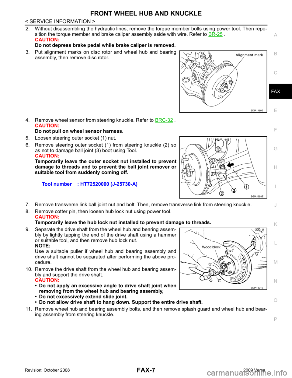
2. Without disassembling the hydraulic lines, remove the torque member bolts using power tool. Then repo-
sition the torque member and brake caliper assembly aside with wire. Refer to BR-25 .
CAUTION:
Do not depress brake pedal while brake caliper is removed.
3. Put alignment marks on disc rotor and wheel hub and bearing assembly, then remove disc rotor.
4. Remove wheel sensor from steering knuckle. Refer to BRC-32 .
CAUTION:
Do not pull on wheel sensor harness.
5. Loosen steering outer socket (1) nut.
6. Remove steering outer socket (1) from steering knuckle (2) so as not to damage ball joint (3) boot using Tool.
CAUTION:
Temporarily leave the outer so cket nut installed to prevent
damage to threads and to pr event the ball joint remover or
suitable tool from suddenly coming off.
7. Remove transverse link ball joint nut and bolt. Then, remove transverse link from steering knuckle.
8. Remove cotter pin, then loosen hub lock nut using power tool. CAUTION:
Temporarily leave the hub lock nut inst alled to prevent damage to threads.
9. Separate the drive shaft from the wheel hub and bearing assem- bly by lightly tapping the end of the drive shaft using a hammer
or suitable tool, and then remove hub lock nut.
NOTE:
Use a suitable puller if wheel hub and bearing assembly and
drive shaft cannot be separated after performing the above pro-
cedure.
10. Remove the drive shaft from the wheel hub and bearing assem- bly and support the drive shaft.
CAUTION:
• Do not apply an excessive angle to drive shaft joint when
removing from the wheel hub and bearing assembly,
• Do not excessively extend slide joint.
• Do not allow drive shaft to hang do wn. Support the entire drive shaft.
11. Remove wheel hub and bearing assembly bolts, and then remove splash guard and wheel hub and bear- ing assembly from steering knuckle.
Page 3246 of 4331
FSU-12< SERVICE INFORMATION >
COIL SPRING AND STRUT
COIL SPRING AND STRUT
Removal and Installation INFOID:0000000004305867
REMOVAL
1. Remove cowl top panel. Refer to EI-22, " Removal and Installation " .
2. Remove front tires using power tool.
3. Remove harness of wheel sensor from strut assembly. Refer to BRC-32, " Removal and Installation " .
CAUTION:
Do not pull on wheel sensor harness.
4. Remove brake hose lock plate. Refer to BR-12, " Rear Brake Tube and Hose " .
5. Remove the nut on the upper side of stabilizer c onnecting rod using power tool, and then remove stabi-
lizer connecting rod from strut assembly.
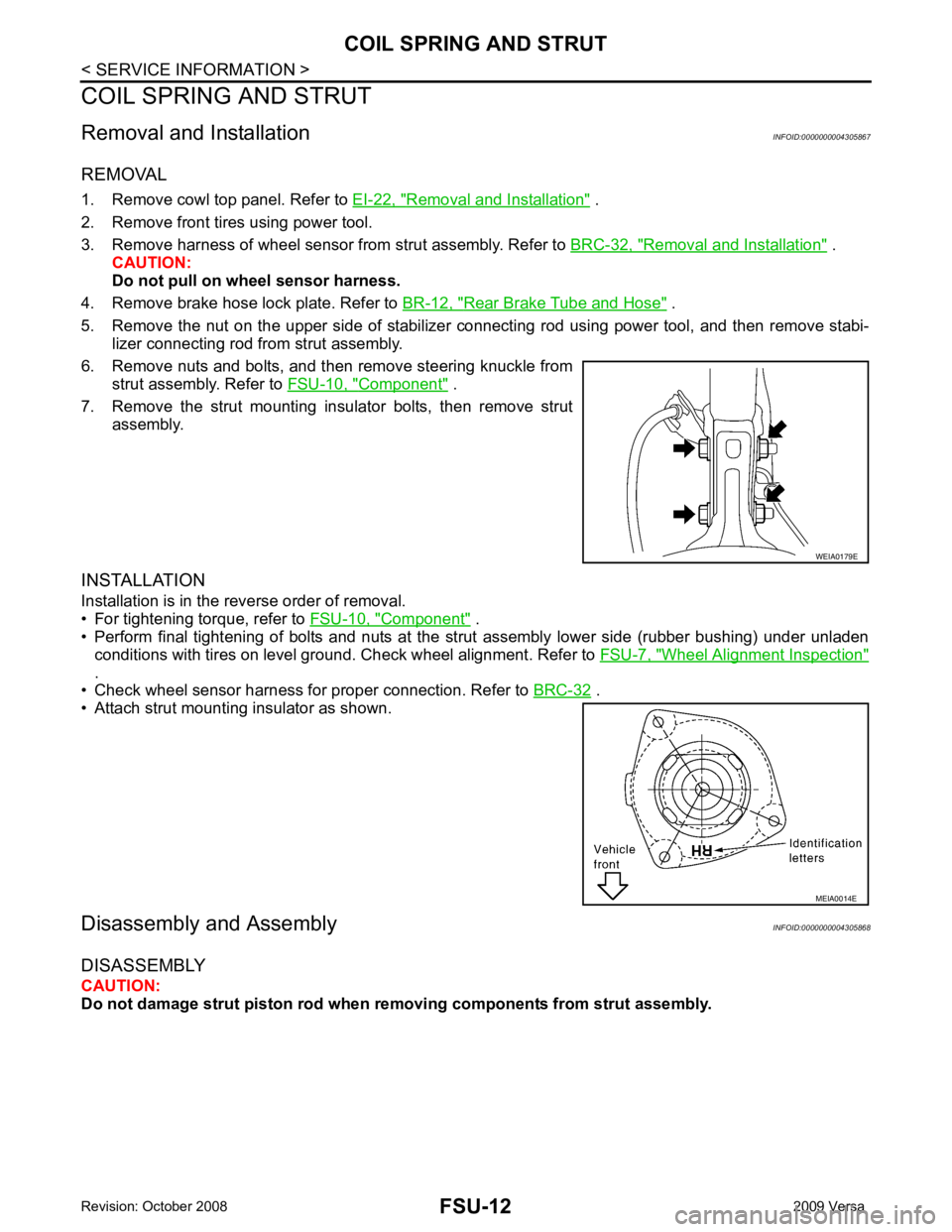
6. Remove nuts and bolts, and then remove steering knuckle from strut assembly. Refer to FSU-10, " Component " .
7. Remove the strut mounting insulator bolts, then remove strut assembly.
INSTALLATION
Installation is in the reverse order of removal.
• For tightening torque, refer to FSU-10, " Component " .
• Perform final tightening of bolts and nuts at the strut assembly lower side (rubber bushing) under unladen
conditions with tires on level ground. Check wheel alignment. Refer to FSU-7, " Wheel Alignment Inspection "
.
• Check wheel sensor harness for proper connection. Refer to BRC-32 .
• Attach strut mounting insulator as shown.
Disassembly and Assembly INFOID:0000000004305868
DISASSEMBLY
CAUTION:
Do not damage strut piston rod when removing components from strut assembly. WEIA0179E
MEIA0014E
Page 3262 of 4331
GI
N
O P
SYMBOLS
How to Follow Trouble Diagnosis INFOID:0000000004307360
DESCRIPTION NOTICE:
Trouble diagnoses indicate work procedures required to diagnose problems effectively. Observe the following
instructions before diagnosing.
1. Before performing trouble diagno ses, read the “Preliminary Check” , the “Symptom Chart” or the
“Work Flow”.
2. After repairs, re-check that the prob lem has been completely eliminated.
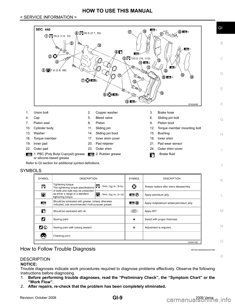
1. Union bolt 2. Copper washer 3. Brake hose
4. Cap 5. Bleed valve 6. Sliding pin bolt
7. Piston seal 8. Piston 9. Piston boot
10. Cylinder body 11. Sliding pin 12. Torque member mounting bolt
13. Washer 14. Sliding pin boot 15. Bushing
16. Torque member 17. Inner shim cover 18. Inner shim
19. Inner pad 20. Pad retainer 21. Pad wear sensor
22. Outer pad 23. Outer shim 24. Outer shim cover 1: PBC (Poly Butyl Cuprysil) grease
or silicone-based grease 2: Rubber grease : Brake fluid
Refer to GI section for additional symbol definitions.
Page 3422 of 4331
LAN
N
O P
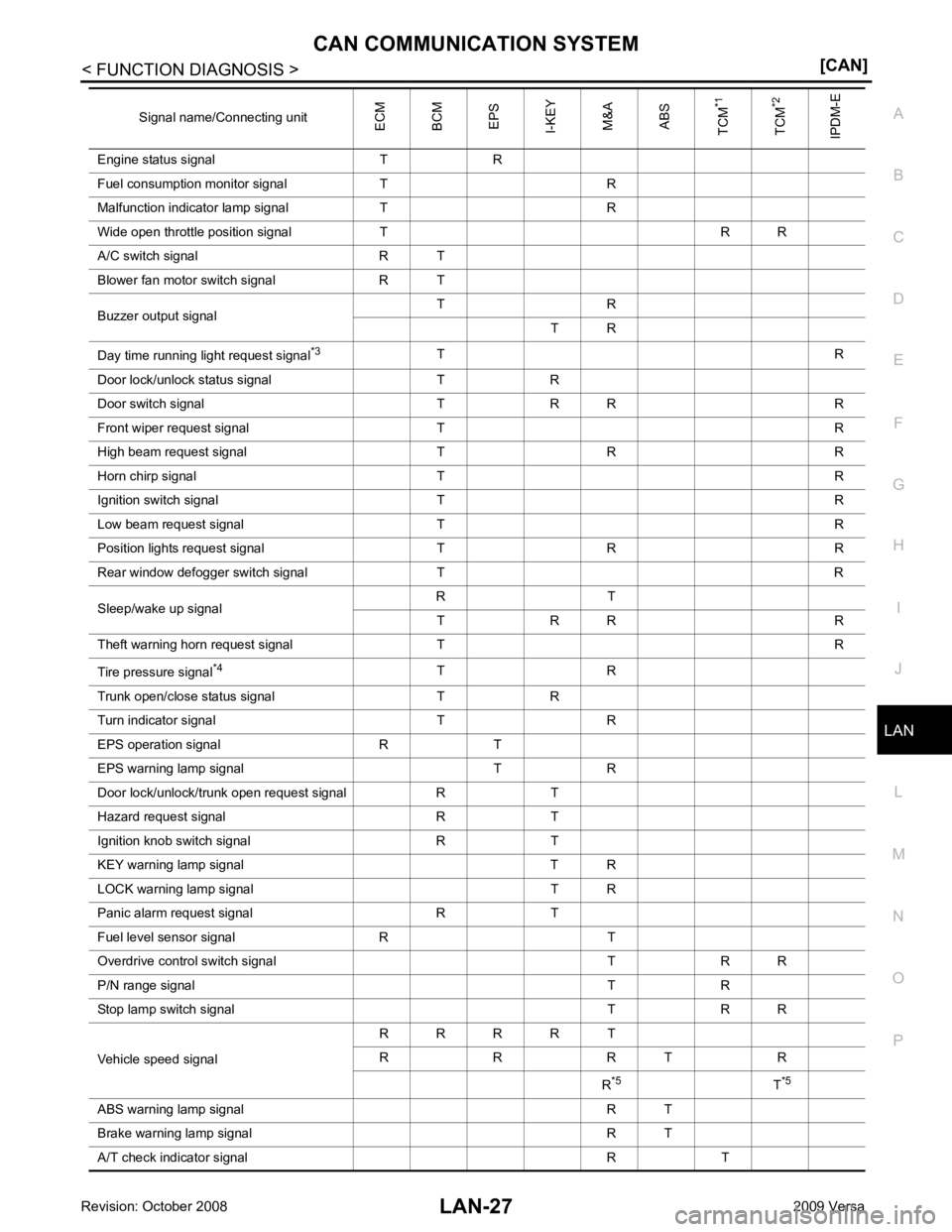
Engine status signal T R
Fuel consumption monitor signal T R
Malfunction indicator lamp signal T R
Wide open throttle position signal T R R
A/C switch signal R T
Blower fan motor switch signal R T
Buzzer output signal T R
T R
Day time running light request signal *3
T R
Door lock/unlock status signal T R
Door switch signal T R R R
Front wiper request signal T R
High beam request signal T R R
Horn chirp signal T R
Ignition switch signal T R
Low beam request signal T R
Position lights request signal T R R
Rear window defogger switch signal T R
Sleep/wake up signal R T
T R R R
Theft warning horn request signal T R
Tire pressure signal *4
T R
Trunk open/close status signal T R
Turn indicator signal T R
EPS operation signal R T
EPS warning lamp signal T R
Door lock/unlock/trunk open request signal R T
Hazard request signal R T
Ignition knob switch signal R T
KEY warning lamp signal T R
LOCK warning lamp signal T R
Panic alarm request signal R T
Fuel level sensor signal R T
Overdrive control switch signal T R R
P/N range signal T R
Stop lamp switch signal T R R
Vehicle speed signal R R R R T
R R R T R
R*5
T*5
ABS warning lamp signal R T
Brake warning lamp signal R T
A/T check indicator signal R T Signal name/Connecting unitECM
BCM EPS
I-KEY
M&AABS
TCM *1
TCM *2
IPDM-E
Page 4040 of 4331
PG
N
O P
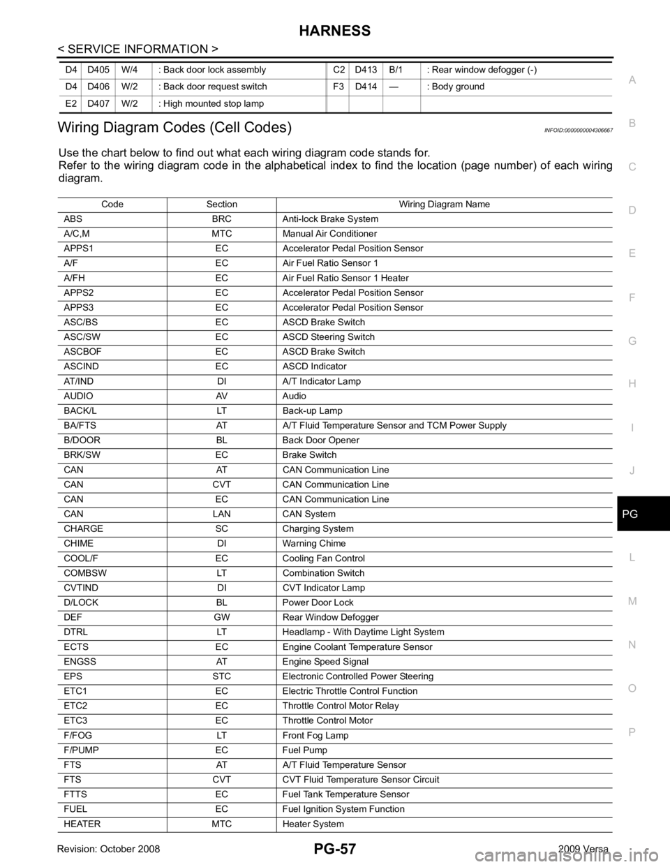
Wiring Diagram Codes (Cell Codes)
INFOID:0000000004306667
Use the chart below to find out what each wiring diagram code stands for.
Refer to the wiring diagram code in the alphabetical index to find the location (page number) of each wiring
diagram. D4 D405 W/4 : Back door lock assembly C2 D413 B/1 : Rear window defogger (-)
D4 D406 W/2 : Back door request switch F3 D414 — : Body ground
E2 D407 W/2 : High mounted stop lamp Code Section Wiring Diagram Name
ABS BRC Anti-lock Brake System
A/C,M MTC Manual Air Conditioner
APPS1 EC Accelerator Pe dal Position Sensor
A/F EC Air Fuel Ratio Sensor 1
A/FH EC Air Fuel Ratio Sensor 1 Heater
APPS2 EC Accelerator Pe dal Position Sensor
APPS3 EC Accelerator Pe dal Position Sensor
ASC/BS EC ASCD Brake Switch
ASC/SW EC ASCD Steering Switch
ASCBOF EC ASCD Brake Switch
ASCIND EC ASCD Indicator
AT/IND DI A/T Indicator Lamp
AUDIO AV Audio
BACK/L LT Back-up Lamp
BA/FTS AT A/T Fluid Temperature Sensor and TCM Power Supply
B/DOOR BL Back Door Opener
BRK/SW EC Brake Switch
CAN AT CAN Communication Line
CAN CVT CAN Comm unication Line
CAN EC CAN Communication Line
CAN LAN CAN System
CHARGE SC Charging System
CHIME DI Warning Chime
COOL/F EC Cooling Fan Control
COMBSW LT Combination Switch
CVTIND DI CVT Indicator Lamp
D/LOCK BL Power Door Lock
DEF GW Rear Window Defogger
DTRL LT Headlamp - Wi th Daytime Light System
ECTS EC Engine Coolant Temperature Sensor
ENGSS AT Engine Speed Signal
EPS STC Electronic Controlled Power Steering
ETC1 EC Electric Throttle Control Function
ETC2 EC Throttle Control Motor Relay
ETC3 EC Throttle Control Motor
F/FOG LT Front Fog Lamp
F/PUMP EC Fuel Pump
FTS AT A/T Fluid Temperature Sensor
FTS CVT CVT Fluid Temperature Sensor Circuit
FTTS EC Fuel Tank Temperature Sensor
FUEL EC Fuel Ignition System Function
HEATER MTC Heater System
Page 4122 of 4331
COIL SPRING
RSU-11
< SERVICE INFORMATION >
C
D
F
G H
I
J
K L
M A
B RSU
N
O P
COIL SPRING
Removal and Installation INFOID:0000000004305882
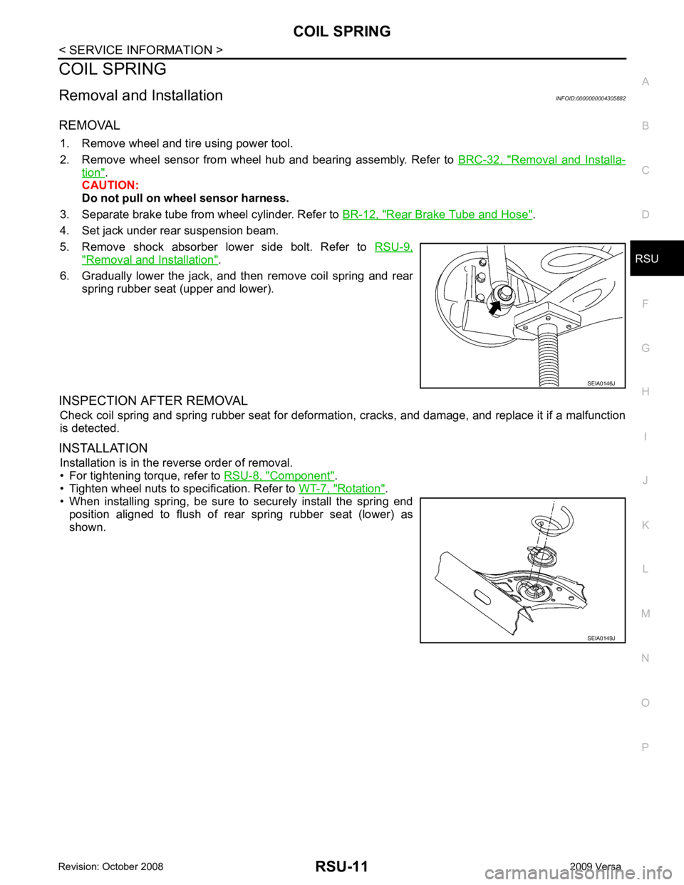
REMOVAL 1. Remove wheel and tire using power tool.
2. Remove wheel sensor from wheel hub and bearing assembly. Refer to BRC-32, " Removal and Installa-
tion " .
CAUTION:
Do not pull on wheel sensor harness.
3. Separate brake tube from wheel cylinder. Refer to BR-12, " Rear Brake Tube and Hose " .
4. Set jack under rear suspension beam.
5. Remove shock absorber lower side bolt. Refer to RSU-9," Removal and Installation " .
6. Gradually lower the jack, and then remove coil spring and rear spring rubber seat (upper and lower).
INSPECTION AFTER REMOVAL Check coil spring and spring rubber seat for deformation, cracks, and damage, and replace it if a malfunction
is detected.
INSTALLATION Installation is in the reverse order of removal.
• For tightening torque, refer to RSU-8, " Component " .
• Tighten wheel nuts to specification. Refer to WT-7, " Rotation " .
• When installing spring, be sure to securely install the spring end
position aligned to flush of rear spring rubber seat (lower) as
shown. SEIA0146J
SEIA0149J
Page 4123 of 4331
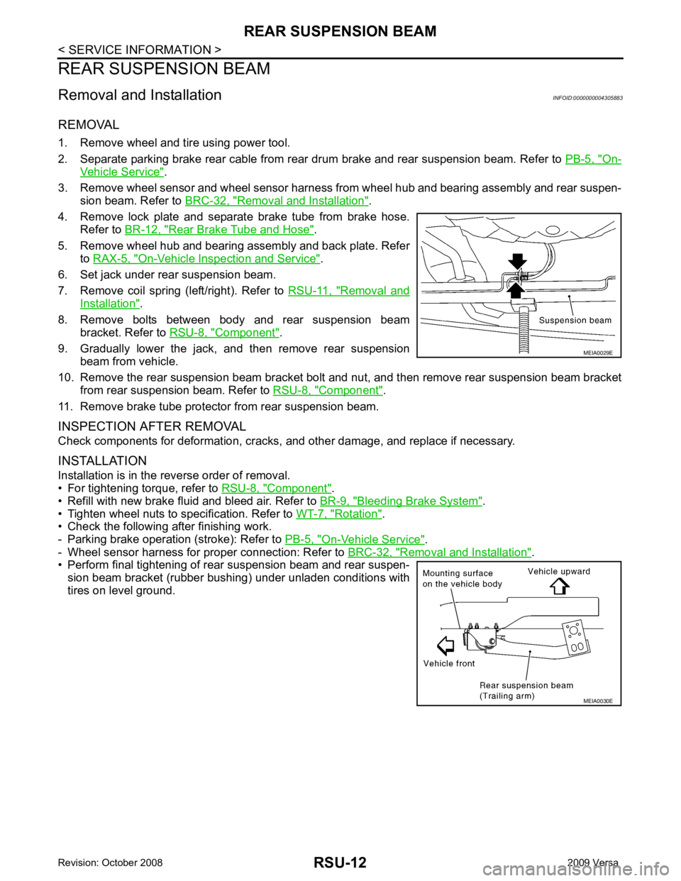
On-
Vehicle Service " .
3. Remove wheel sensor and wheel sensor harness from wheel hub and bearing assembly and rear suspen-
sion beam. Refer to BRC-32, " Removal and Installation " .
4. Remove lock plate and separate brake tube from brake hose. Refer to BR-12, " Rear Brake Tube and Hose " .
5. Remove wheel hub and bearing assembly and back plate. Refer to RAX-5, " On-Vehicle Inspection and Service " .
6. Set jack under rear suspension beam.
7. Remove coil spring (left/right). Refer to RSU-11, " Removal and
Installation " .
8. Remove bolts between body and rear suspension beam bracket. Refer to RSU-8, " Component " .
9. Gradually lower the jack, and then remove rear suspension beam from vehicle.
10. Remove the rear suspension beam bracket bolt and nut, and then remove rear suspension beam bracket
from rear suspension beam. Refer to RSU-8, " Component " .
11. Remove brake tube protector from rear suspension beam.
INSPECTION AFTER REMOVAL
Check components for deformation, cracks, and other damage, and replace if necessary.
INSTALLATION
Installation is in the reverse order of removal.
• For tightening torque, refer to RSU-8, " Component " .
• Refill with new brake fluid and bleed air. Refer to BR-9, " Bleeding Brake System " .
• Tighten wheel nuts to specification. Refer to WT-7, " Rotation " .
• Check the following after finishing work.
- Parking brake operation (stroke): Refer to PB-5, " On-Vehicle Service " .
- Wheel sensor harness for proper connection: Refer to BRC-32, " Removal and Installation " .
• Perform final tightening of rear suspension beam and rear suspen-
sion beam bracket (rubber bushing) under unladen conditions with
tires on level ground. MEIA0030E