2009 NISSAN TIIDA brake sensor
[x] Cancel search: brake sensorPage 971 of 4331
CVT
N
O P
Optimize the line pressure and secondary pressure, dependi
ng on driving conditions, on the basis of the throt-
tle position, the engine speed, the primary pulley (input ) revolution speed, the secondary pulley (output) revo-
lution speed, the brake signal, the PNP switch signal, the lock-up signal, the voltage, the target gear ratio, the
fluid temperature, and the fluid pressure.
FEEDBACK CONTROL When controlling the normal fluid pressure or the sele cted fluid pressure, the secondary pressure can be set
more accurately by using the fluid pressure sensor to detect the secondary pressure and controlling the feed-
back.
Shift Control INFOID:0000000004666872
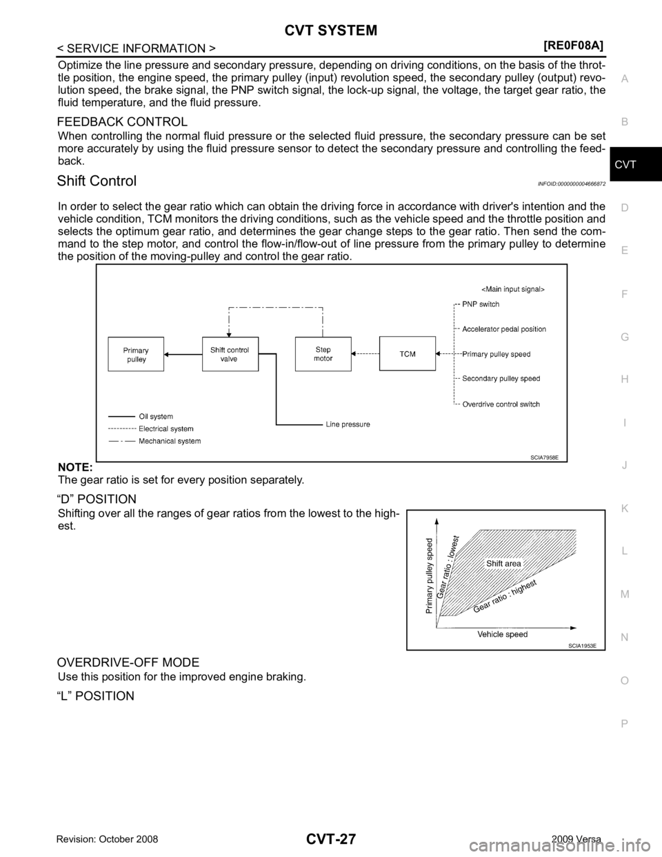
In order to select the gear ratio which can obtain the dr iving force in accordance with driver's intention and the
vehicle condition, TCM monitors the driving conditions, such as the vehicle speed and the throttle position and
selects the optimum gear ratio, and determines the gear change steps to the gear ratio. Then send the com-
mand to the step motor, and control the flow-in/flow-out of line pressure from the primary pulley to determine
the position of the moving-pul ley and control the gear ratio.
NOTE:
The gear ratio is set for every position separately.
“D” POSITION Shifting over all the ranges of gear ra tios from the lowest to the high-
est.
OVERDRIVE-OFF MODE Use this position for the improved engine braking.
“L” POSITION
Page 998 of 4331
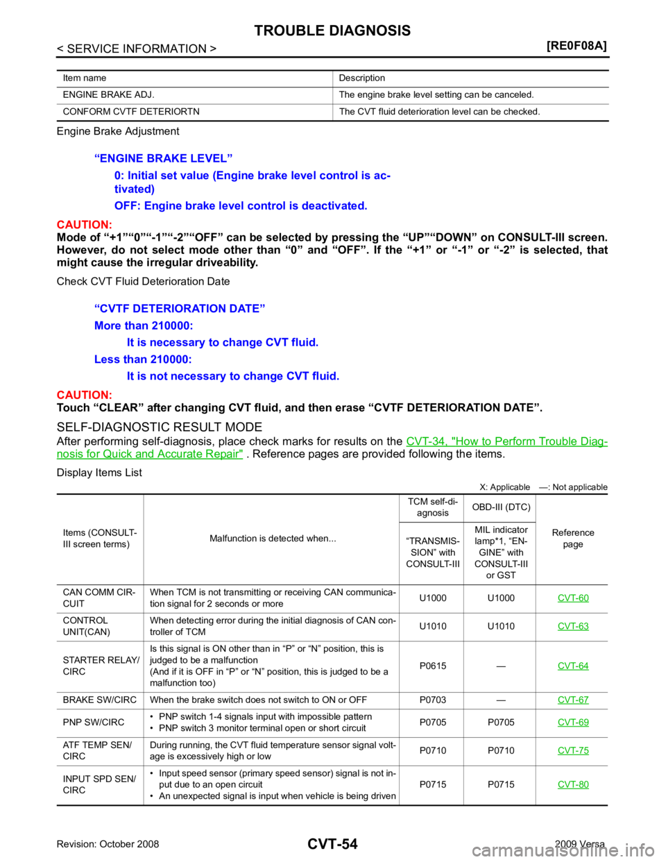
How to Perform Trouble Diag-
nosis for Quick and Accurate Repair " . Reference pages are provided following the items.
Display Items List X: Applicable —: Not applicable
Item name Description
ENGINE BRAKE ADJ. The engine brake level setting can be canceled.
CONFORM CVTF DETERIORTN The CVT fluid deterioration level can be checked. CONTROL
UNIT(CAN) When detecting error during the initial diagnosis of CAN con-
troller of TCM U1010 U1010
CVT-63STARTER RELAY/
CIRC Is this signal is ON other than in “P” or “N” position, this is
judged to be a malfunction
(And if it is OFF in “P” or “N” position, this is judged to be a
malfunction too) P0615 —
CVT-64BRAKE SW/CIRC When the brake switch does
not switch to ON or OFF P0703 — CVT-67PNP SW/CIRC
• PNP switch 1-4 signals input with impossible pattern
• PNP switch 3 monitor terminal open or short circuit P0705 P0705
CVT-69ATF TEMP SEN/
CIRC During running, the CVT fluid temperature sensor signal volt-
age is excessively high or low P0710 P0710
CVT-75INPUT SPD SEN/
CIRC • Input speed sensor (primary speed sensor) signal is not in-
put due to an open circuit
• An unexpected signal is input when vehicle is being driven P0715 P0715
CVT-80
Page 1147 of 4331
![NISSAN TIIDA 2009 Service Repair Manual CVT SYSTEM
CVT-203
< SERVICE INFORMATION >
[RE0F08B] D
E
F
G H
I
J
K L
M A
B CVT
N
O P
Hydraulic Control System
INFOID:0000000004305575
TCM Function INFOID:0000000004305576
The function of the TCM is NISSAN TIIDA 2009 Service Repair Manual CVT SYSTEM
CVT-203
< SERVICE INFORMATION >
[RE0F08B] D
E
F
G H
I
J
K L
M A
B CVT
N
O P
Hydraulic Control System
INFOID:0000000004305575
TCM Function INFOID:0000000004305576
The function of the TCM is](/manual-img/5/57398/w960_57398-1146.png)
CVT SYSTEM
CVT-203
< SERVICE INFORMATION >
[RE0F08B] D
E
F
G H
I
J
K L
M A
B CVT
N
O P
Hydraulic Control System
INFOID:0000000004305575
TCM Function INFOID:0000000004305576
The function of the TCM is to:
• Receive input signals sent from various switches and sensors.
• Determine required line pressure, shifting point, and lock-up operation.
• Send required output signals to the step motor and the respective solenoids.
CONTROL SYSTEM OUTLINE The CVT senses vehicle operating conditions through vari ous sensors. It always controls the optimum shift
position and reduces shifting and lock-up shocks. SCIA1807E
SENSORS (or SIGNAL)
⇒TCM
⇒ACTUATORS
PNP switch
Accelerator pedal position signal
Closed throttle position signal
Engine speed signal
CVT fluid temperature sensor
Vehicle speed signal
Overdrive control signal
Stop lamp switch signal
Primary speed sensor
Secondary speed sensor
Secondary pressure sensor Shift control
Line pressure control
Primary pressure control
Secondary pressure control
Lock-up control
Engine brake control
Vehicle speed control
Fail-safe control
Self-diagnosis
CONSULT-III co mmunication
line
Duet-EA control
CAN system
On board diagnosis Step motor
Torque converter clutch solenoid
valve
Lock-up select solenoid valve
Line pressure solenoid valve
Secondary pressure solenoid
valve
Shift position indicator
O/D OFF indicator lamp
Starter relay
Page 1149 of 4331
![NISSAN TIIDA 2009 Service Repair Manual CVT SYSTEM
CVT-205
< SERVICE INFORMATION >
[RE0F08B] D
E
F
G H
I
J
K L
M A
B CVT
N
O P
*1: Input by CAN communications.
*2: Output by CAN communications.
*3: If these input and output signals are diff NISSAN TIIDA 2009 Service Repair Manual CVT SYSTEM
CVT-205
< SERVICE INFORMATION >
[RE0F08B] D
E
F
G H
I
J
K L
M A
B CVT
N
O P
*1: Input by CAN communications.
*2: Output by CAN communications.
*3: If these input and output signals are diff](/manual-img/5/57398/w960_57398-1148.png)
CVT SYSTEM
CVT-205
< SERVICE INFORMATION >
[RE0F08B] D
E
F
G H
I
J
K L
M A
B CVT
N
O P
*1: Input by CAN communications.
*2: Output by CAN communications.
*3: If these input and output signals are different, the TCM triggers the fail-safe function.
Line Pressure and Secondary Pressure Control INFOID:0000000004305579
• When an input torque signal equivalent to the engine drive force is sent from the ECM to the TCM, the TCM
controls the line pressure solenoid valve and secondary pressure solenoid valve.
• This line pressure solenoid controls the pressure regulat or valve as the signal pressure and adjusts the pres-
sure of the operating oil discharged from the oil pump to the line pressure most appropriate to the driving
state. Secondary pressure is cont rolled by decreasing line pressure.
NORMAL CONTROL Optimize the line pressure and secondary pressure, dependi ng on driving conditions, on the basis of the throt-
tle position, the engine speed, the primary pulley (input ) revolution speed, the secondary pulley (output) revo-
lution speed, the brake signal, the PNP switch signal, the lock-up signal, the voltage, the target gear ratio, the
fluid temperature, and the fluid pressure.
FEEDBACK CONTROL When controlling the normal fluid pressure or the sele cted fluid pressure, the secondary pressure can be set
more accurately by using the fluid pressure sensor to detect the secondary pressure and controlling the feed-
back.
Shift Control INFOID:0000000004305580
In order to select the gear ratio which can obtain the dr iving force in accordance with driver's intention and the
vehicle condition, TCM monitors the driving conditions, such as the vehicle speed and the throttle position and
selects the optimum gear ratio, and determines the gear change steps to the gear ratio. Then send the com-
Out-
put Step motor X X
TCC solenoid valve X X X
Lock-up select solenoid valve X X X
Line pressure solenoid valve X X X X
Secondary pressure solenoid valve X X X
O/D OFF indicator signal (*2)
X X
Control item
Fluid
pressure
control Select con-
trol Shift control
Lock-up
control CAN com-
munication
control Fail-safe
function
(*3) SCIA1846E
Page 1177 of 4331
CVT
N
O P
CAUTION:
Touch “CLEAR” after changing CVT fluid, and then erase “CVTF DETERIORATION DATE”.
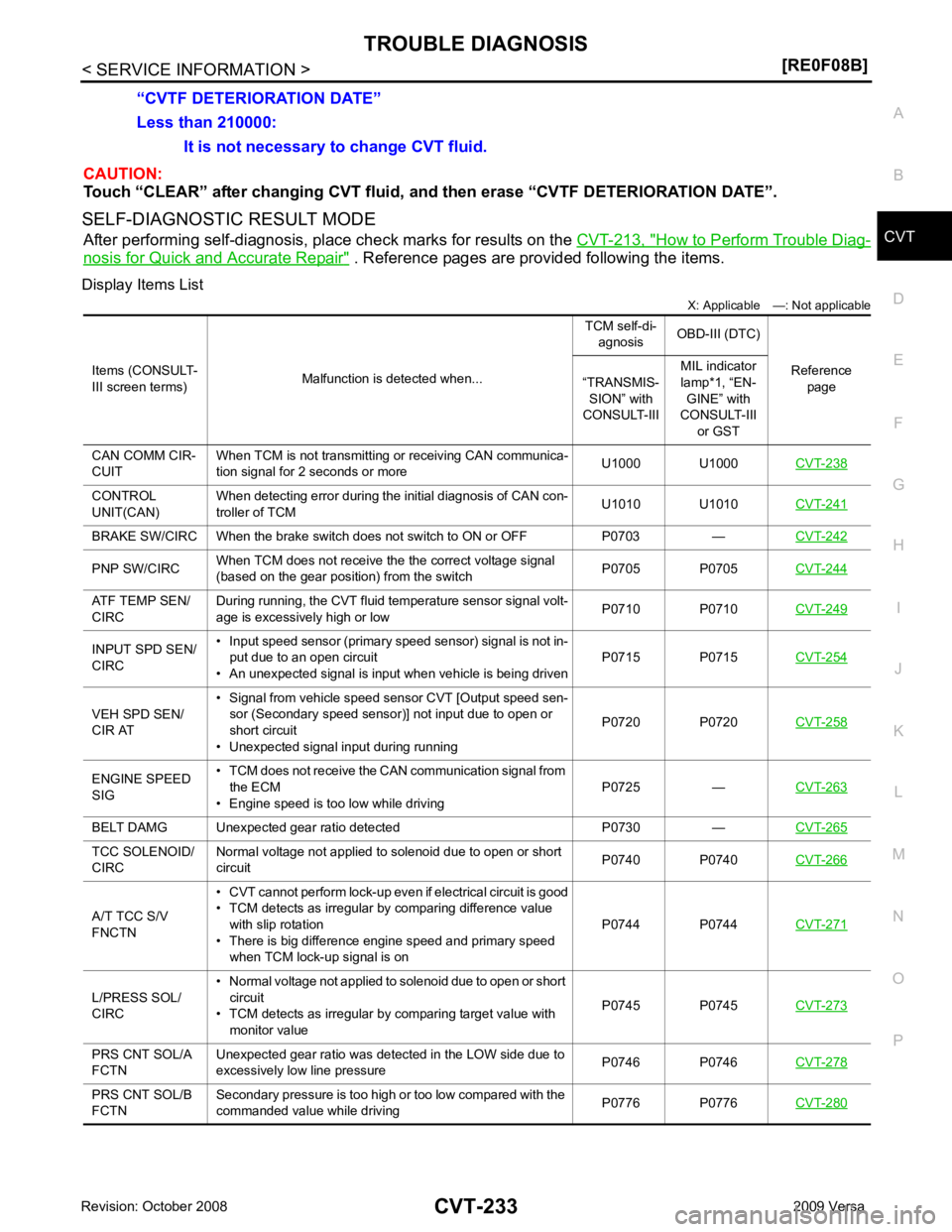
SELF-DIAGNOSTIC RESULT MODE After performing self-diagnosis, place check marks for results on the CVT-213, " How to Perform Trouble Diag-
nosis for Quick and Accurate Repair " . Reference pages are provided following the items.
Display Items List X: Applicable —: Not applicable
Less than 210000:
It is not necessary to change CVT fluid.
“CVTF DETERIORATION DATE”
Items (CONSULT-
III screen terms) Malfunction is detected when... TCM self-di-
agnosis OBD-III (DTC)
Reference page
“TRANSMIS-
SION” with
CONSULT-III MIL indicator
lamp*1, “EN- GINE” with
CONSULT-III
or GST
CAN COMM CIR-
CUIT When TCM is not transmitting or receiving CAN communica-
tion signal for 2 seconds or more U1000 U1000
CVT-238CONTROL
UNIT(CAN) When detecting error during the initial diagnosis of CAN con-
troller of TCM U1010 U1010
CVT-241BRAKE SW/CIRC When the brake switch does not switch to ON or OFF P0703 —
CVT-242PNP SW/CIRC
When TCM does not receive the the correct voltage signal
(based on the gear position) from the switch P0705 P0705
CVT-244ATF TEMP SEN/
CIRC During running, the CVT fluid temperature sensor signal volt-
age is excessively high or low P0710 P0710
CVT-249INPUT SPD SEN/
CIRC • Input speed sensor (primary speed sensor) signal is not in-
put due to an open circuit
• An unexpected signal is input when vehicle is being driven P0715 P0715
CVT-254VEH SPD SEN/
CIR AT • Signal from vehicle speed sensor CVT [Output speed sen-
sor (Secondary speed sensor)] not input due to open or
short circuit
• Unexpected signal input during running P0720 P0720
CVT-258ENGINE SPEED
SIG • TCM does not receive the CAN communication signal from
the ECM
• Engine speed is too low while driving P0725 —
CVT-263BELT DAMG Unexpected gear ratio detected P0730 —
CVT-265TCC SOLENOID/
CIRC Normal voltage not applied to solenoid due to open or short
circuit P0740 P0740
CVT-266A/T TCC S/V
FNCTN • CVT cannot perform lock-up even if electrical circuit is good
• TCM detects as irregular by comparing difference value with slip rotation
• There is big difference engine speed and primary speed
when TCM lock-up signal is on P0744 P0744
CVT-271L/PRESS SOL/
CIRC • Normal voltage not applied to solenoid due to open or short
circuit
• TCM detects as irregular by comparing target value with
monitor value P0745 P0745
CVT-273PRS CNT SOL/A
FCTN Unexpected gear ratio was detected in the LOW side due to
excessively low line pressure P0746 P0746
CVT-278PRS CNT SOL/B
FCTN Secondary pressure is too high or too low compared with the
commanded value while driving P0776 P0776
CVT-280
Page 1303 of 4331
DI
N
O P
CONTENTS
DRIVER INFORMATION SYSTEM
SERVICE INFORMATION .. ..........................2
PRECAUTION ................................................ .....2
Precaution for Supplemental Restraint System
(SRS) "AIR BAG" and "SEAT BELT PRE-TEN-
SIONER" ............................................................. ......
2
COMBINATION METERS .............................. .....3
Component Parts and Harness Connector Loca-
tion ...................................................................... ......
3
System Description ............................................. ......3
Arrangement of Combination Meter .................... ......5
Internal Circuit ..................................................... ......6
Wiring Diagram - METER - ................................. ......7
Combination Meter Harness Connector Terminal
Layout ................................................................. ......
9
Terminal and Reference Value for Combination
Meter ................................................................... ......
9
Self-Diagnosis Mode of Combination Meter ........ ....10
CONSULT-III Function (METER/M&A) ............... ....12
Trouble Diagnosis ............................................... ....13
Symptom Chart ................................................... ....14
Power Supply and Ground Circuit Inspection ..... ....14
Vehicle Speed Signal Inspection ......................... ....15
Engine Speed Signal Inspection ......................... ....16
Fuel Level Sensor Signal Inspection ................... ....16
Fuel Gauge Fluctuates, Indicates Wrong Value, or
Varies .................................................................. ....
18
Fuel Gauge Does Not Move to Full-position ...........18
DTC [U1000] CAN Communication Circuit ......... ....18
Electrical Component Inspection ......................... ....19
Removal and Installation .........................................19
WARNING LAMPS ......................................... ....20
Schematic ........................................................... ....20
Wiring Diagram - WARN - ................................... ....21 Oil Pressure Wa
rning Lamp Stays Off (Ignition
Switch ON) .......................................................... ....
29
Oil Pressure Wa rning Lamp Does Not Turn Off
(Oil Pressure Is Normal) ...................................... ....
31
Component Inspection ......................................... ....31
A/T INDICATOR ................................................ 33
System Description .............................................. ....33
Wiring Diagram - AT/IND - ................................... ....34
A/T Indicator Does Not Illuminate ........................ ....35
CVT INDICATOR ............................................... 37
System Description .............................................. ....37
Schematic ............................................................ ....37
Wiring Diagram - CVTIND - ................................. ....38
CVT Indicator Does Not Illuminate ...................... ....40
WARNING CHIME ............................................. 42
Component Parts and Harness Connector Loca-
tion ....................................................................... ....
42
System Description .............................................. ....42
Wiring Diagram - CHIME - ................................... ....45
Terminal and Reference Value for BCM ..................46
CONSULT-III Function (B CM) .................................46
Trouble Diagnosis ................................................ ....47
Combination Meter Buzzer Cir cuit Inspection .........48
Front Door Switch LH Signal Inspection .............. ....49
Key Switch Signal Inspec tion (Without Intelligent
Key) ..................................................................... ....
50
Key Switch and Ignition Knob Switch Signal In-
spection (With Intelligent Key, When Mechanical
Key Is Used) ........................................................ ....
51
Lighting Switch Signal Inspection ........................ ....53
Parking Brake Switch Signal Inspection .............. ....53
Electrical Component Inspection ......................... ....54
Page 1312 of 4331
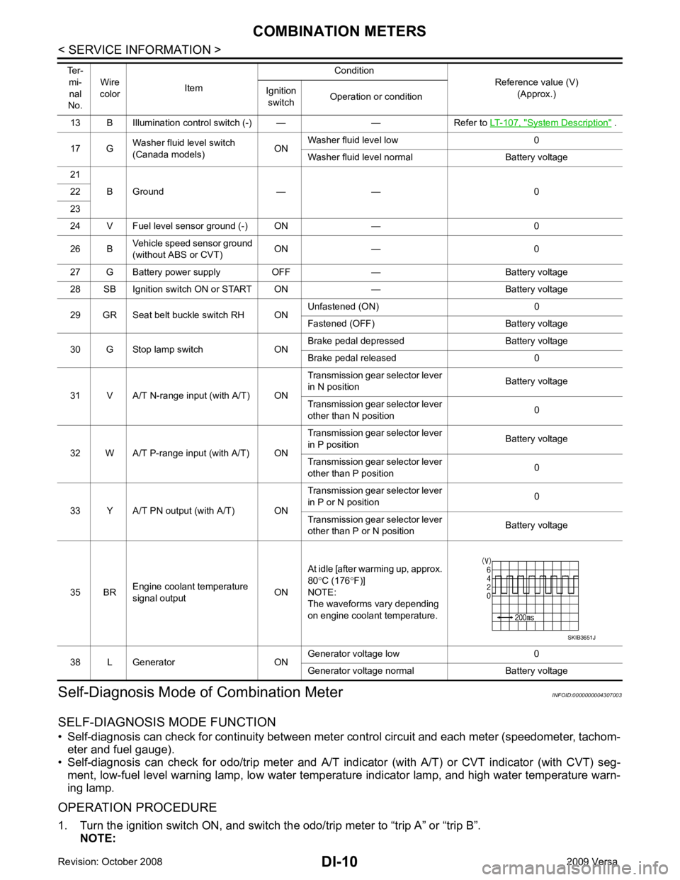
System Description " .
17 G Washer fluid level switch
(Canada models) ONWasher fluid level low 0
Washer fluid level normal Battery voltage
21 B Ground — — 0
22
23
24 V Fuel level sensor ground (-) ON — 0
26 B Vehicle speed sensor ground
(without ABS or CVT) ON — 0
27 G Battery power supply OFF — Battery voltage
28 SB Ignition switch ON or START ON — Battery voltage
29 GR Seat belt buckle switch RH ON Unfastened (ON) 0
Fastened (OFF) Battery voltage
30 G Stop lamp switch ON Brake pedal depressed Battery voltage
Brake pedal released 0
31 V A/T N-range input (with A/T) ON Transmission gear selector lever
in N position Battery voltage
Transmission gear selector lever
other than N position 0
32 W A/T P-range input (with A/T) ON Transmission gear selector lever
in P position Battery voltage
Transmission gear selector lever
other than P position 0
33 Y A/T PN output (with A/T) ON Transmission gear selector lever
in P or N position 0
Transmission gear selector lever
other than P or N position Battery voltage
35 BR Engine coolant temperature
signal output ONAt idle [after warming up, approx.
80 °C (176 °F)]
NOTE:
The waveforms vary depending
on engine coolant temperature.
38 L Generator ON Generator voltage low 0
Generator voltage normal Battery voltage
Ter-
mi-
nal
No. Wire
color Item Condition
Reference value (V)
(Approx.)
Ignition
switch Operation or condition
Page 1361 of 4331

EC
A
N
O P
Diagnosis Procedure ...........................................
..
349
P0507 ISC SYSTEM ....................................... ..351
Description .......................................................... ..351
DTC Logic ........................................................... ..351
Diagnosis Procedure ........................................... ..351
P0603 ECM POWER SUPPLY ....................... ..353
Description .......................................................... ..353
DTC Logic ........................................................... ..353
Diagnosis Procedure ........................................... ..353
P0605 ECM ..................................................... ..355
Description .......................................................... ..355
DTC Logic ........................................................... ..355
Diagnosis Procedure ........................................... ..356
P0607 ECM ..................................................... ..357
Description .......................................................... ..357
DTC Logic ........................................................... ..357
Diagnosis Procedure ........................................... ..357
P0643 SENSOR POWER SUPPLY ............... ..358
DTC Logic ........................................................... ..358
Wiring Diagram ................................................... ..359
Diagnosis Procedure ........................................... ..359
P0850 PNP SWITCH ...................................... ..362
Description .......................................................... ..362
DTC Logic ........................................................... ..362
Component Function Check ................................ ..363
Wiring Diagram ................................................... ..364
Diagnosis Procedure ........................................... ..364
P1148 CLOSED LOOP CONTROL ................ ..367
DTC Logic ........................................................... ..367
P1217 ENGINE OVER TEMPERATURE ....... ..368
DTC Logic ........................................................... ..368
Component Function Check ................................ ..368
Diagnosis Procedure ........................................... ..369
P1225 TP SENSOR ........................................ ..372
Description .......................................................... ..372
DTC Logic ........................................................... ..372
Diagnosis Procedure ........................................... ..372
Special Repair Requirem ent .................................373
P1226 TP SENSOR ........................................ ..374
Description .......................................................... ..374
DTC Logic ........................................................... ..374
Diagnosis Procedure ........................................... ..374
Special Repair Requirem ent .................................375
P1421 COLD START CONTROL ................... ..376
Description .......................................................... ..376
DTC Logic ........................................................... ..376
Diagnosis Procedure ........................................... ..376
P1715 INPUT SPEED SENSOR (PRIMARY
SPEED SENSOR) .......................................... ..
378
Description .......................................................... ..378 DTC Logic ............................................................
..378
Diagnosis Procedure ........................................... ..378
P1805 BRAKE SWITCH ................................. 380
Description ........................................................... ..380
DTC Logic ............................................................ ..380
Wiring Diagram .................................................... ..381
Diagnosis Procedure ........................................... ..381
Component Inspection (Stop Lamp Switch) ........ ..383
P2100, P2103 THROTTLE CONTROL MO-
TOR RELAY .................................................... 384
Description ........................................................... ..384
DTC Logic ............................................................ ..384
Wiring Diagram .................................................... ..385
Diagnosis Procedure ........................................... ..385
P2101 ELECTRIC THROTTLE CONTROL
FUNCTION ....... ............................................... 388
Description ........................................................... ..388
DTC Logic ............................................................ ..388
Wiring Diagram .................................................... ..389
Diagnosis Procedure ........................................... ..389
Component Inspection ......................................... ..392
Special Repair Requiremen t ..................................392
P2118 THROTTLE CONTROL MOTOR ......... 393
Description ........................................................... ..393
DTC Logic ............................................................ ..393
Wiring Diagram .................................................... ..394
Diagnosis Procedure ........................................... ..394
Component Inspection ......................................... ..395
Special Repair Requiremen t ..................................396
P2119 ELECTRIC THROTTLE CONTROL
ACTUATOR ..................................................... 397
Description ........................................................... ..397
DTC Logic ............................................................ ..397
Diagnosis Procedure ........................................... ..397
Special Repair Requiremen t ..................................398
P2122, P2123 APP SENSOR ......................... 399
Description ........................................................... ..399
DTC Logic ............................................................ ..399
Wiring Diagram .................................................... ..400
Diagnosis Procedure ........................................... ..400
Component Inspection ......................................... ..402
Special Repair Requiremen t ..................................402
P2127, P2128 APP SENSOR ......................... 403
Description ........................................................... ..403
DTC Logic ............................................................ ..403
Wiring Diagram .................................................... ..404
Diagnosis Procedure ........................................... ..404
Component Inspection ......................................... ..406
Special Repair Requiremen t ..................................407
P2135 TP SENSOR ......................................... 408
Description ........................................................... ..408
DTC Logic ............................................................ ..408