Page 727 of 4331
“ DIFFERENCE OF KEY ” displayed?
YES >> GO TO 2
NO >> GO TO BL-259, " Trouble Diagnosis " .
YES >> • Ignition key ID was unregistered.
NO >> • BCM is malfunctioning.
• Replace BCM. Refer to BCS-18, " Removal and Installation of BCM " .
• Perform initialization with CONSULT-III.
• For initialization, refer to CONSULT-III Operation Manual.
How to Replace NATS Antenna Amp INFOID:0000000004305150
NOTE:
• If NATS antenna amp. is not installed correctly, NATS system
will not operate properly and SELF-DIAG RESULTS on CON-
SULT-III screen will show “LOCK MODE” or “CHAIN OF IMMU-
KEY”.
• Initialization is not necessary only when NATS antenna amp.
is replaced with a new one.
Page 803 of 4331

BR
N
O P
5. When the repair work is completed, return the ignition switch to the
″LOCK ″ position before connecting
the battery cables. (At this time, the steering lock mechanism will engage.)
6. Perform a self-diagnosis check of al l control units using CONSULT-III.
Precaution for Brake System INFOID:0000000004305887
• Refill using recommended brake fluid. Refer to MA-14 .
• Never reuse drained brake fluid.
• Be careful not to splash brake fluid on painted surfac e of body. If brake fluid is splashed on painted surfaces
of body immediately wipe it off with cloth and then wash it away with water.
• To clean or wash all parts of master cylinder, disc brake caliper and wheel cylinder, use new brake fluid.
• Never use mineral oils such as gasoline or kerosene. They will ruin rubber parts of the hydraulic system.
• Use a flare nut wrench when removing a brake tube and use a flare nut torque wrench when installing a brake tube.
• When installing brake tubes and hoses, be sure to check torque.
• Before working, turn igniti on switch OFF and disconnect connec-
tors of ABS actuator and electric unit (control unit) or the battery
cable from the negative terminal.
• Burnish the new braking surfaces after refinishing or replacing drums or rotors, after replacing p ads or linings, or if a soft pedal
occurs at very low mileage. Refer to BR-32, " Brake Burnishing
Procedure " .
Page 807 of 4331
BR
N
O P
2. Loosen lock nut on input rod, then rotate input rod to set pedal to
the specified height, and tighten the lock nut.
CAUTION:
Make sure that the threaded end of input rod stays inside
clevis.
3. With the pedal pulled and held by hand, press stop lamp switch and ASCD switch until their threaded end contacts the brake
pedal stopper.
4. With the threaded end of stop lamp switch and ASCD switch contacting brake pedal stopper, rotate the switches clockwise by
45 ° to secure.
CAUTION:
Make sure that the clearance (C) is within specification.
5. Check that the stop lamps go out when the brake pedal is released.
CAUTION:
Make sure that stop lamps go off when brake pedal is
released.
6. Start the engine and check the brake pedal stroke.
Removal and Installation INFOID:0000000004305891
COMPONENTS
REMOVAL Lock nut : Refer to
BR-21, " Removal and Installation " .
Page 812 of 4331

Fluids and Lubricants " .
• Never reuse drained brake fluid.
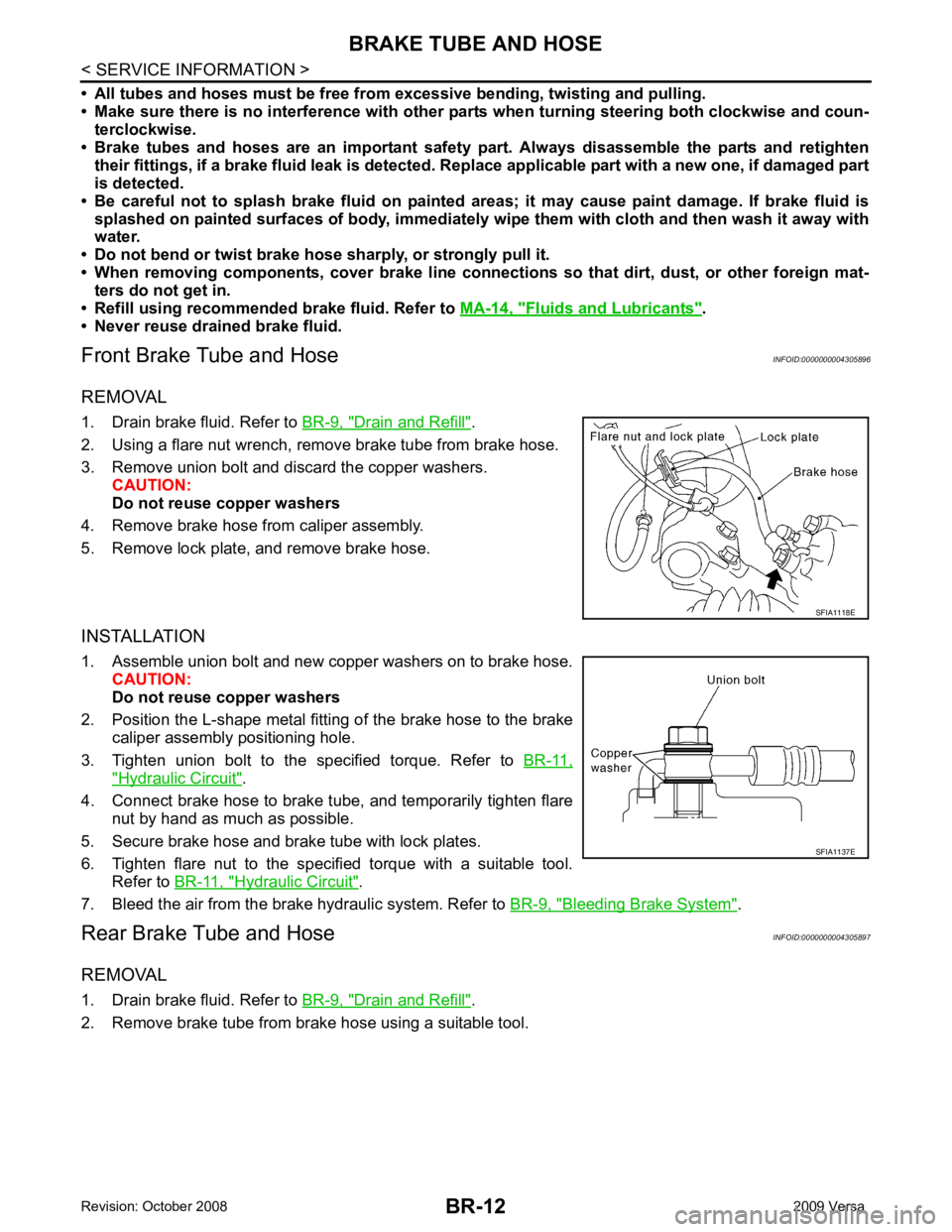
Front Brake Tube and Hose INFOID:0000000004305896
REMOVAL
1. Drain brake fluid. Refer to BR-9, " Drain and Refill " .
2. Using a flare nut wrench, remove brake tube from brake hose.
3. Remove union bolt and discard the copper washers. CAUTION:
Do not reuse copper washers
4. Remove brake hose from caliper assembly.
5. Remove lock plate, and remove brake hose.
INSTALLATION
1. Assemble union bolt and new copper washers on to brake hose. CAUTION:
Do not reuse copper washers
2. Position the L-shape metal fitting of the brake hose to the brake caliper assembly positioning hole.
3. Tighten union bolt to the specified torque. Refer to BR-11," Hydraulic Circuit " .
4. Connect brake hose to brake tube, and temporarily tighten flare nut by hand as much as possible.
5. Secure brake hose and brake tube with lock plates.
6. Tighten flare nut to the specified torque with a suitable tool. Refer to BR-11, " Hydraulic Circuit " .
7. Bleed the air from the brake hydraulic system. Refer to BR-9, " Bleeding Brake System " .
Rear Brake Tube and Hose INFOID:0000000004305897
REMOVAL
1. Drain brake fluid. Refer to BR-9, " Drain and Refill " .
2. Remove brake tube from brake hose using a suitable tool.
Page 813 of 4331

BR
N
O P
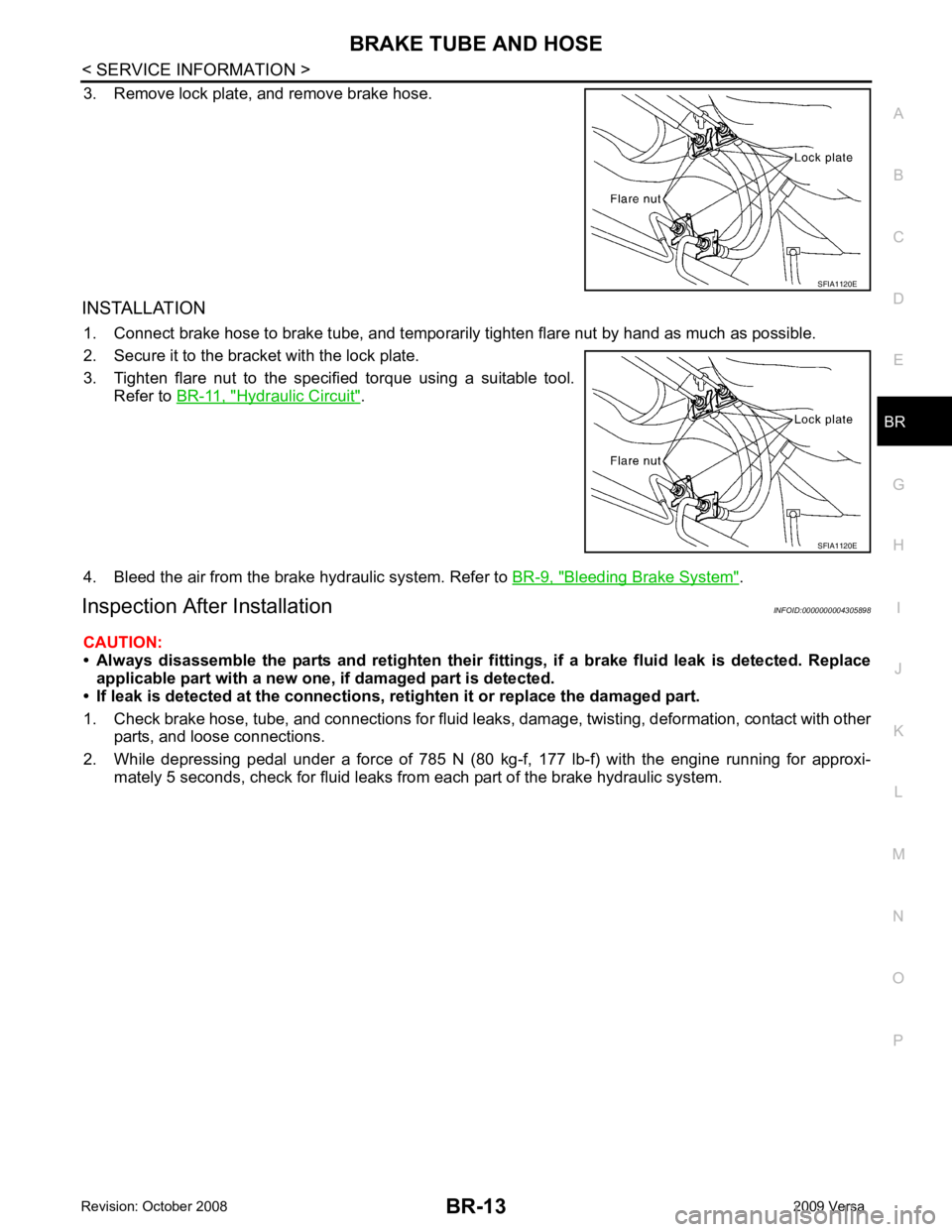
3. Remove lock plate, and remove brake hose.
INSTALLATION 1. Connect brake hose to brake tube, and temporaril y tighten flare nut by hand as much as possible.
2. Secure it to the bracket with the lock plate.
3. Tighten flare nut to the specified torque using a suitable tool. Refer to BR-11, " Hydraulic Circuit " .
4. Bleed the air from the brake hydraulic system. Refer to BR-9, " Bleeding Brake System " .
Inspection After Installation INFOID:0000000004305898
CAUTION:
• Always disassemble the parts and retighten their fitti ngs, if a brake fluid leak is detected. Replace
applicable part with a new one, if damaged part is detected.
• If leak is detected at the connections, retighten it or replace the damaged part.
1. Check brake hose, tube, and connections for fluid leak s, damage, twisting, deformation, contact with other
parts, and loose connections.
2. While depressing pedal under a force of 785 N (80 kg-f, 177 lb-f) with the engine running for approxi- mately 5 seconds, check for fluid leaks from each part of the brake hydraulic system. SFIA1120E
Page 822 of 4331
Inspection and Adjustment " .
7. Tighten lock nut of input rod to the specified torque.
8. Install vacuum hose into brake booster. Refer to BR-23, " Removal and Installation " .
9. Bleed the air from the brake hydraulic system. Refer to BR-9, " Bleeding Brake System " .
Input rod length (B) : Refer to
BR-40, " Brake Booster " .
Page 830 of 4331

BR-30< SERVICE INFORMATION >
FRONT DISC BRAKE
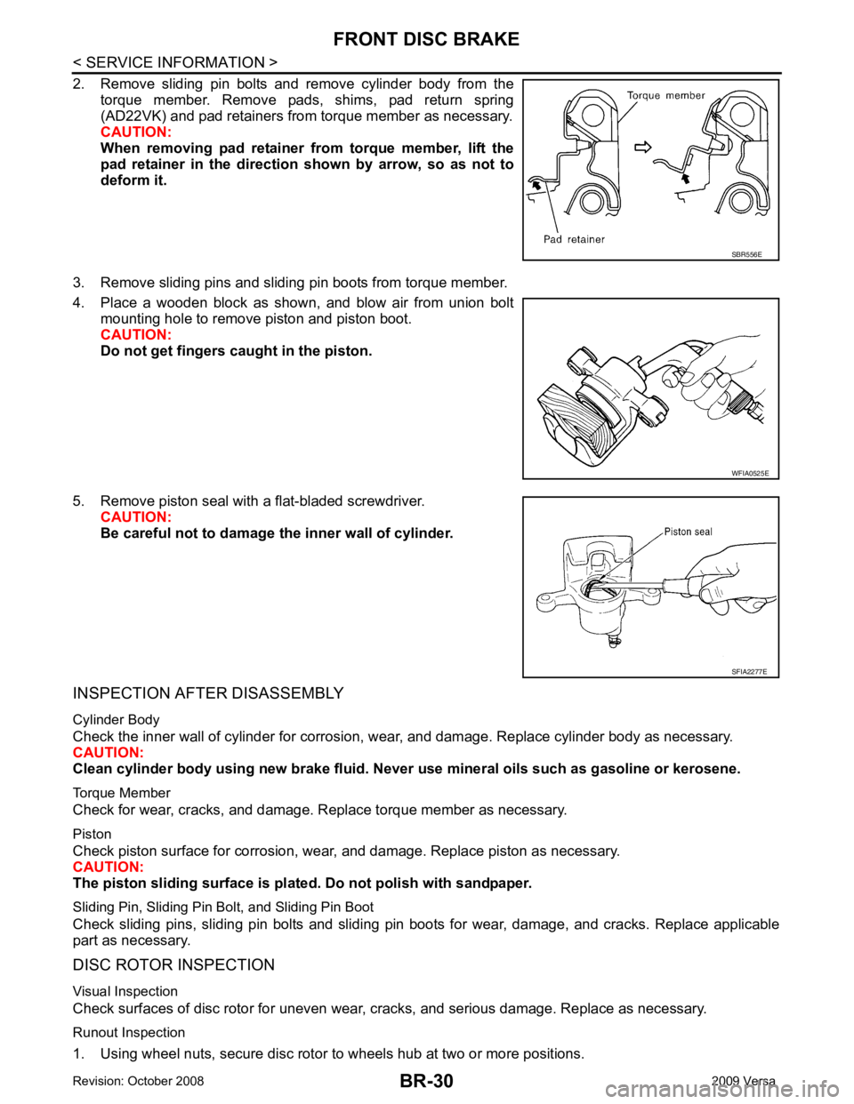
2. Remove sliding pin bolts and remove cylinder body from the torque member. Remove pads, shims, pad return spring
(AD22VK) and pad retainers from torque member as necessary.
CAUTION:
When removing pad retainer fr om torque member, lift the
pad retainer in the direction shown by arrow, so as not to
deform it.
3. Remove sliding pins and sliding pin boots from torque member.
4. Place a wooden block as shown, and blow air from union bolt mounting hole to remove piston and piston boot.
CAUTION:
Do not get fingers caught in the piston.
5. Remove piston seal with a flat-bladed screwdriver. CAUTION:
Be careful not to damage the inner wall of cylinder.
INSPECTION AFTER DISASSEMBLY
Cylinder Body
Check the inner wall of cylinder for corrosion, w ear, and damage. Replace cylinder body as necessary.
CAUTION:
Clean cylinder body using new brake fluid. Never use mineral oils such as gasoline or kerosene.
Torque Member
Check for wear, cracks, and damage. R eplace torque member as necessary.
Piston
Check piston surface for corrosion, wear, and damage. Replace piston as necessary.
CAUTION:
The piston sliding surface is plated . Do not polish with sandpaper.
Sliding Pin, Sliding Pin Bolt, and Sliding Pin Boot
Check sliding pins, sliding pin bolts and sliding pin boots for wear, damage, and cracks. Replace applicable
part as necessary.
DISC ROTOR INSPECTION
Visual Inspection
Check surfaces of disc rotor for uneven wear, cr acks, and serious damage. Replace as necessary.
Runout Inspection
1. Using wheel nuts, secure disc rotor to wheels hub at two or more positions. SBR556E
WFIA0525E
SFIA2277E
Page 845 of 4331

BRC
N
O P
SYSTEM DESCRIPTION
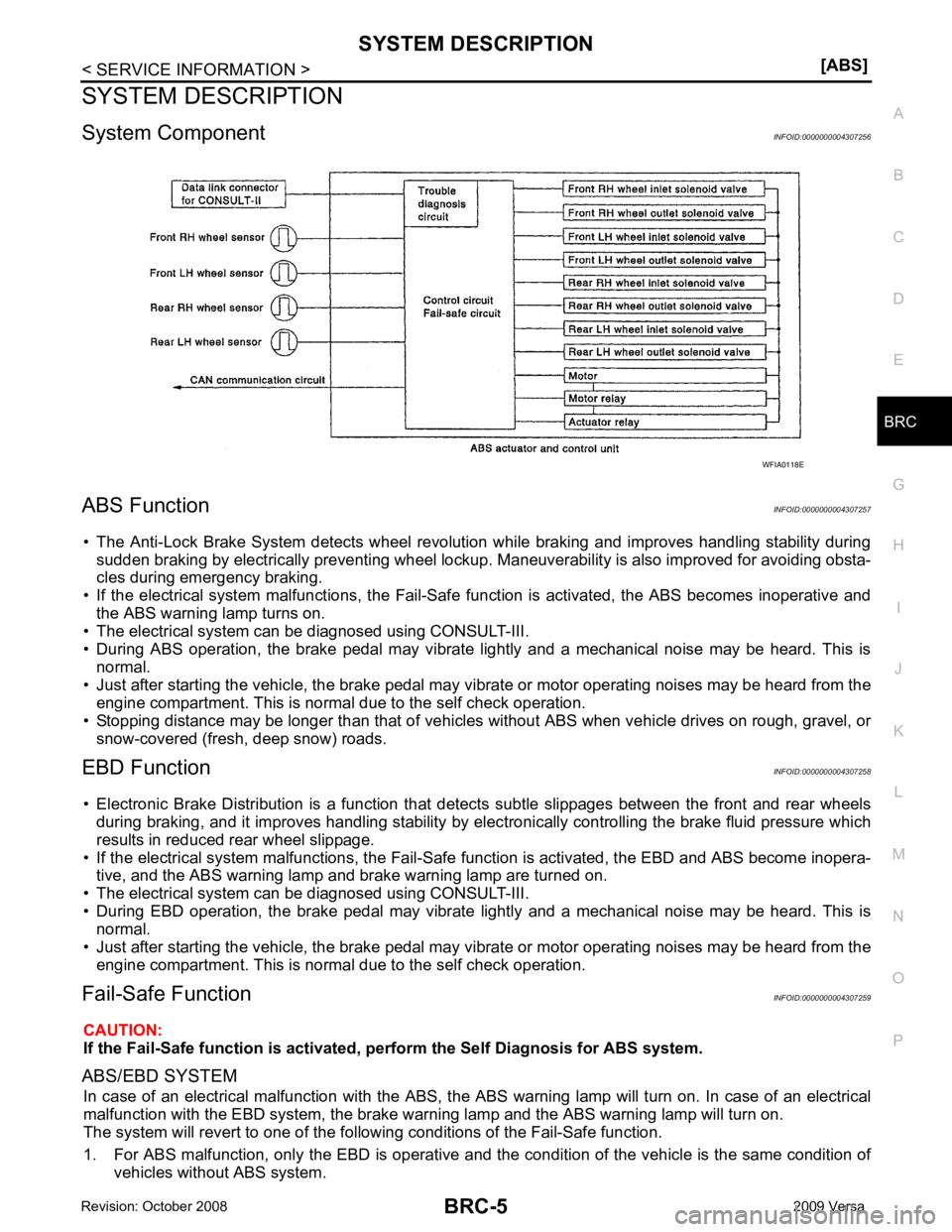
System Component INFOID:0000000004307256
ABS Function INFOID:0000000004307257
• The Anti-Lock Brake System detects wheel revolution while braking and improves handling stability during sudden braking by electrically preventing wheel lockup. Maneuverability is also improved for avoiding obsta-
cles during emergency braking.
• If the electrical system malfunctions, the Fail-Safe function is activated, the ABS becomes inoperative and
the ABS warning lamp turns on.
• The electrical system can be diagnosed using CONSULT-III.
• During ABS operation, the brake pedal may vibrate lightly and a mechanical noise may be heard. This is
normal.
• Just after starting the vehicle, the brake pedal may vibrate or motor operating noises may be heard from the
engine compartment. This is normal due to the self check operation.
• Stopping distance may be longer than that of vehicles without ABS when vehicle drives on rough, gravel, or
snow-covered (fresh, deep snow) roads.
EBD Function INFOID:0000000004307258
• Electronic Brake Distribution is a function that detec ts subtle slippages between the front and rear wheels
during braking, and it improves handling stability by elec tronically controlling the brake fluid pressure which
results in reduced rear wheel slippage.
• If the electrical system malfunctions, the Fail-Safe function is activated, the EBD and ABS become inopera-
tive, and the ABS warning lamp and brake warning lamp are turned on.
• The electrical system can be diagnosed using CONSULT-III.
• During EBD operation, the brake pedal may vibrate lightly and a mechanical noise may be heard. This is
normal.
• Just after starting the vehicle, the brake pedal may vibrate or motor operating noises may be heard from the
engine compartment. This is normal due to the self check operation.
Fail-Safe Function INFOID:0000000004307259
CAUTION:
If the Fail-Safe function is activated, perform the Self Diagnosis for ABS system.
ABS/EBD SYSTEM In case of an electrical malfunction with the ABS, the ABS warning lamp wi ll turn on. In case of an electrical
malfunction with the EBD system, the brake warni ng lamp and the ABS warning lamp will turn on.
The system will revert to one of the follo wing conditions of the Fail-Safe function.
1. For ABS malfunction, only the EBD is operative and t he condition of the vehicle is the same condition of
vehicles without ABS system.