2009 NISSAN TIIDA lock
[x] Cancel search: lockPage 673 of 4331
BL-212< SERVICE INFORMATION >
TRUNK LID OPENER
OK or NG OK >> GO TO 6
NG >> Repair or replace harness. 6.
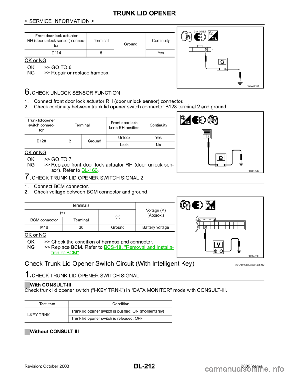
CHECK UNLOCK SENSOR FUNCTION
1. Connect front door lock actuator RH (door unlock sensor) connector.
2. Check continuity between trunk lid opener switch connector B128 terminal 2 and ground.
OK or NG OK >> GO TO 7
NG >> Replace front door lock actuator RH (door unlock sen- sor). Refer to BL-166 .
7.
CHECK TRUNK LID OPENER SWITCH SIGNAL 2
1. Connect BCM connector.
2. Check voltage between BCM connector and ground.
OK or NG OK >> Check the condition of harness and connector.
NG >> Replace BCM. Refer to BCS-18, " Removal and Installa-
tion of BCM " .
Check Trunk Lid Opener Switch Circuit (With Intelligent Key) INFOID:00000000043051121.
CHECK TRUNK LID OPENER SWITCH SIGNAL
With CONSULT-III
Check trunk lid opener switch (“I-KEY TRNK”) in “DATA MONI TOR” mode with CONSULT-III.
Without CONSULT-III Front door lock actuator
RH (door unlock sensor) connec-
tor Terminal
GroundContinuity
D114 5 Yes WIIA1273E
Trunk lid opener
switch connec- tor Terminal
Front door lock
knob RH position Continuity
B128 2 Ground Unlock Yes
Lock No PIIB6472E
Terminals
Voltage (V)
(Approx.)
(+)
(–)
BCM connector Terminal
M18 30 Ground Battery voltage PIIB6468E
Test item Condition
I-KEY TRNK Trunk lid opener switch is pushed: ON (momentarily)
Trunk lid opener switch is released: OFF
Page 675 of 4331
BL-214< SERVICE INFORMATION >
TRUNK LID OPENER
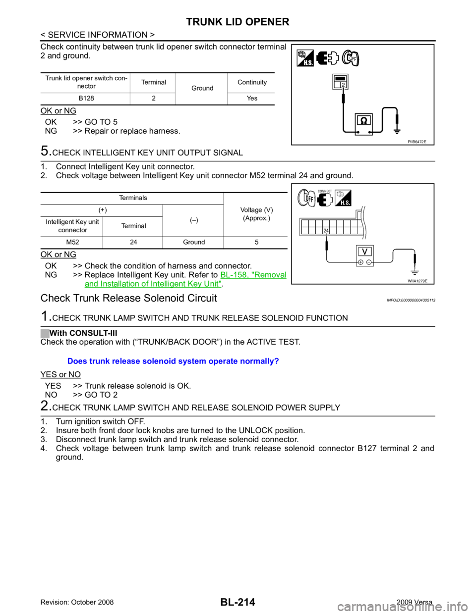
Check continuity between trunk lid opener switch connector terminal
2 and ground.
OK or NG OK >> GO TO 5
NG >> Repair or replace harness. 5.
CHECK INTELLIGENT KEY UNIT OUTPUT SIGNAL
1. Connect Intelligent Key unit connector.
2. Check voltage between Intelligent Key unit connector M52 terminal 24 and ground.
OK or NG OK >> Check the condition of harness and connector.
NG >> Replace Intelligent Key unit. Refer to BL-158, " Removal
and Installation of Intelligent Key Unit " .
Check Trunk Releas e Solenoid Circuit INFOID:00000000043051131.
CHECK TRUNK LAMP SWITCH AND T RUNK RELEASE SOLENOID FUNCTION
With CONSULT-III
Check the operation with (“TRUNK/BACK DOOR”) in the ACTIVE TEST.
YES or NO YES >> Trunk release solenoid is OK.
NO >> GO TO 2 2.
CHECK TRUNK LAMP SWITCH AND RE LEASE SOLENOID POWER SUPPLY
1. Turn ignition switch OFF.
2. Insure both front door lock knobs are turned to the UNLOCK position.
3. Disconnect trunk lamp switch and trunk release solenoid connector.
4. Check voltage between trunk lamp switch and trunk release solenoid connector B127 terminal 2 and ground.
Trunk lid opener switch con-
nector Terminal
GroundContinuity
B128 2 Yes PIIB6472E
Terminals
Voltage (V)(Approx.)
(+)
(–)
Intelligent Key unit
connector Terminal
M52 24 Ground 5 WIIA1279E
Does trunk release solenoid
system operate normally?
Page 678 of 4331
BL
N
O P
FUEL FILLER LID OPENER
Removal and Installation of Fuel Filler Lid Opener INFOID:0000000004305114
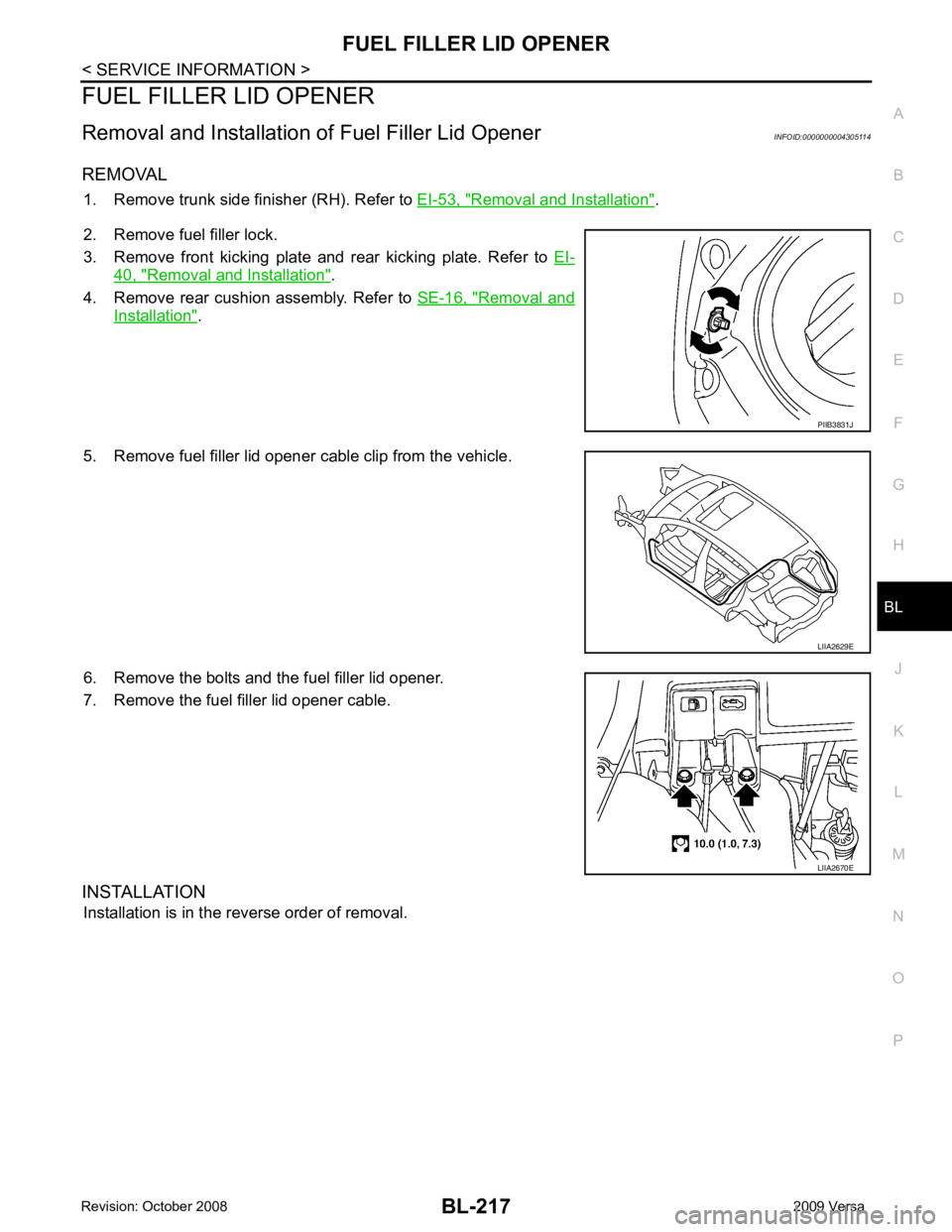
REMOVAL 1. Remove trunk side finisher (RH). Refer to EI-53, " Removal and Installation " .
2. Remove fuel filler lock.
3. Remove front kicking plate and rear kicking plate. Refer to EI-40, " Removal and Installation " .
4. Remove rear cushion assembly. Refer to SE-16, " Removal and
Installation " .
5. Remove fuel filler lid opener cable clip from the vehicle.
6. Remove the bolts and the fuel filler lid opener.
7. Remove the fuel filler lid opener cable.
INSTALLATION Installation is in the reverse order of removal. LIIA2629E
Page 680 of 4331
BL
N
O P
System Description
INFOID:0000000004305116
DESCRIPTION
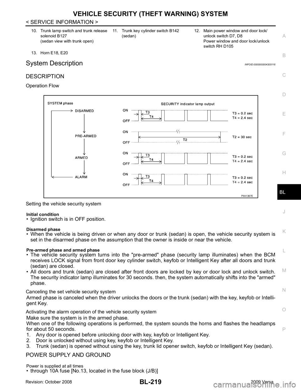
Operation Flow
Setting the vehicle security system Initial condition
• Ignition switch is in OFF position.
Disarmed phase
• When the vehicle is being driven or when any door or tr unk (sedan) is open, the vehicle security system is
set in the disarmed phase on the assumption that the owner is inside or near the vehicle.
Pre-armed phase and armed phase
• The vehicle security system turns into the "pre- armed" phase (security lamp illuminates) when the BCM
receives LOCK signal from front door key cylinder s witch, keyfob or Intelligent Key after all doors and trunk
(sedan) are closed.
• All doors and trunk (sedan) are closed after front door s are locked by key or door lock and unlock switch.
The security indicator lamp illuminates for 30 seconds. t hen, the system automatically shifts into the "armed"
phase.
Canceling the set vehicle security system Armed phase is canceled when the driver unlocks the doors or the trunk (sedan) with the key, keyfob or Intelli-
gent Key.
Activating the alarm operation of the vehicle security system Make sure the system is in the armed phase.
When one of the following operations is performed, the system sounds the horns and flashes the headlamps
for about 50 seconds.
1. Any door is opened before unlocking door with key, keyfob or Intelligent Key.
2. Door is unlocked without using key, keyfob or Intelligent Key.
3. Trunk (sedan) is opened without using the key, trunk lid opener switch, keyfob or Intelligent Key (sedan).
POWER SUPPLY AND GROUND
Power is supplied at all times
• through 10A fuse [No.13, located in the fuse block (J/B)] 10. Trunk lamp switch and trunk release
solenoid B127
(sedan view with trunk open) 11. Trunk key cylinder switch B142
(sedan) 12. Main power window and door lock/
unlock switch D7, D8
Power window and door lock/unlock
switch RH D105
13. Horn E18, E20
Page 688 of 4331
VEHICLE SECURITY (THEFT WARNING) SYSTEM
BL-227
< SERVICE INFORMATION >
C
D E
F
G H
J
K L
M A
B BL
N
O P
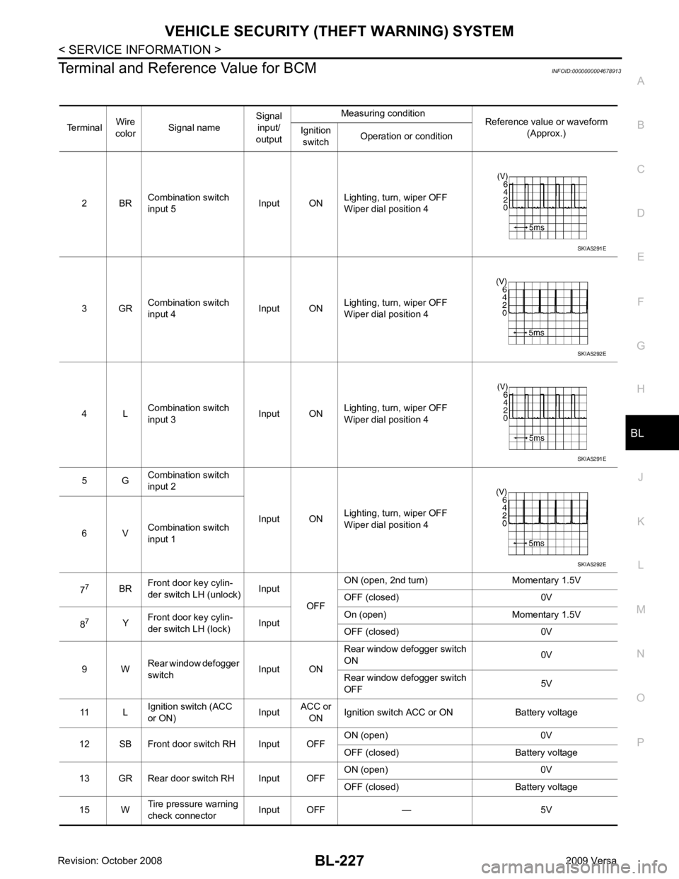
Terminal and Reference Value for BCM
INFOID:0000000004678913
Terminal Wire
color Signal name Signal
input/
output Measuring condition
Reference value or waveform
(Approx.)
Ignition
switch Operation or condition
2 BR Combination switch
input 5 Input ONLighting, turn, wiper OFF
Wiper dial position 4
3 GR Combination switch
input 4 Input ONLighting, turn, wiper OFF
Wiper dial position 4
4 L Combination switch
input 3 Input ONLighting, turn, wiper OFF
Wiper dial position 4
5 G Combination switch
input 2
Input ONLighting, turn, wiper OFF
Wiper dial position 4
6 V Combination switch
input 1
7 7
BRFront door key cylin-
der switch LH (unlock) Input
OFFON (open, 2nd turn) Momentary 1.5V
OFF (closed) 0V
8 7
YFront door key cylin-
der switch LH (lock) InputOn (open) Momentary 1.5V
OFF (closed) 0V
9 W Rear window defogger
switch Input ONRear window defogger switch
ON 0V
Rear window defogger switch
OFF 5V
11 L Ignition switch (ACC
or ON) InputACC or
ON Ignition switch ACC or ON Battery voltage
12 SB Front door switch RH Input OFF ON (open) 0V
OFF (closed) Battery voltage
13 GR Rear door switch RH Input OFF ON (open) 0V
OFF (closed) Battery voltage
15 W Tire pressure warning
check connector Input OFF — 5V SKIA5291E
SKIA5292E
SKIA5291E
SKIA5292E
Page 690 of 4331
VEHICLE SECURITY (THEFT WARNING) SYSTEM
BL-229
< SERVICE INFORMATION >
C
D E
F
G H
J
K L
M A
B BL
N
O P
30
1
VBack door/trunk out-
put Output —Back door open (switch
closed) 0V
Back door closed (switch
open) 5V
30 3
VBack door opener
switch Input —All doors locked (SW OFF) Battery voltage
All doors unlocked (SW ON) 0V
30 4
VTrunk lid opener
switch Input —All doors locked (SW OFF) Battery voltage
All doors unlocked (SW ON) 0V
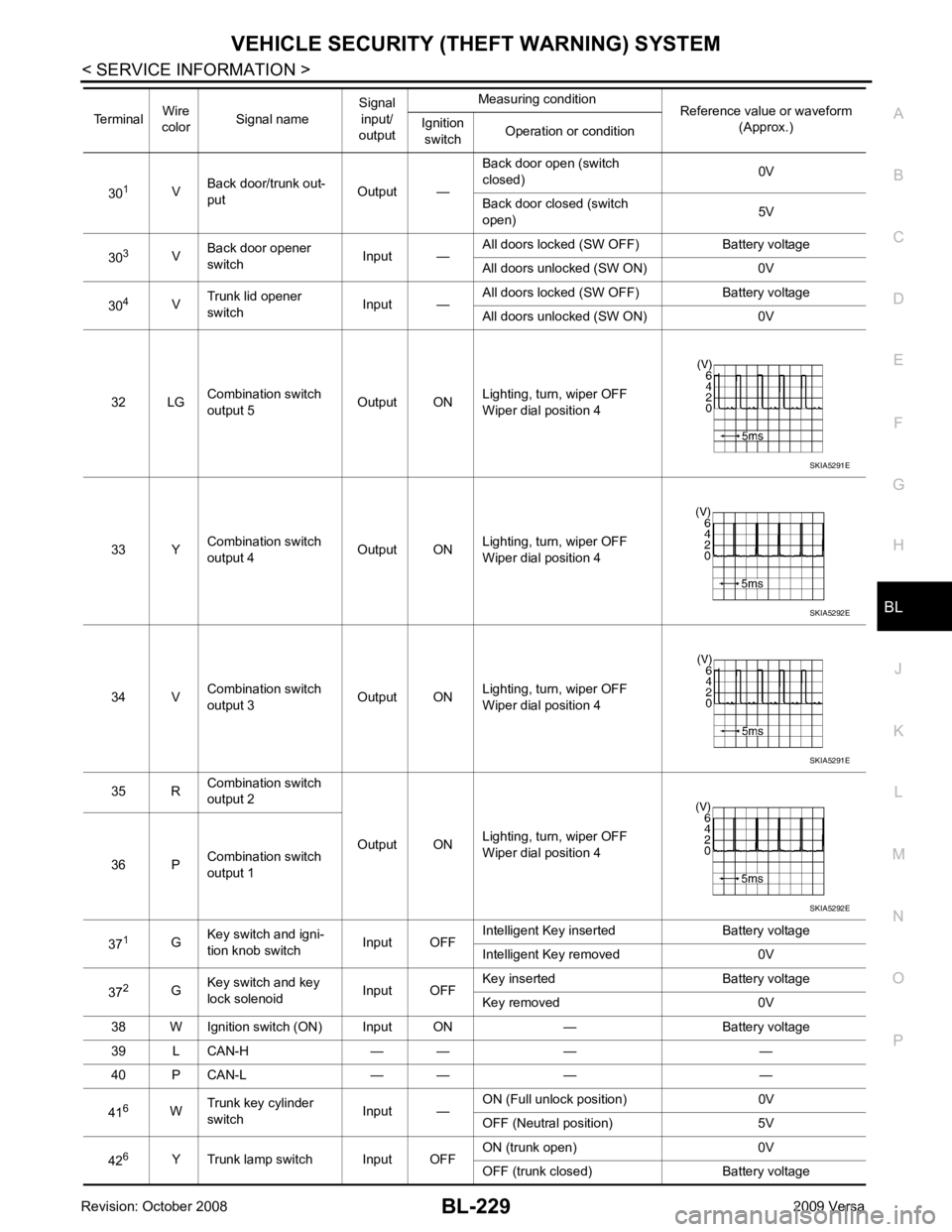
32 LG Combination switch
output 5 Output ONLighting, turn, wiper OFF
Wiper dial position 4
33 Y Combination switch
output 4 Output ON
Lighting, turn, wiper OFF
Wiper dial position 4
34 V Combination switch
output 3 Output ONLighting, turn, wiper OFF
Wiper dial position 4
35 R Combination switch
output 2
Output ONLighting, turn, wiper OFF
Wiper dial position 4
36 P Combination switch
output 1
37 1
GKey switch and igni-
tion knob switch Input OFFIntelligent Key inserted Battery voltage
Intelligent Key removed 0V
37 2
GKey switch and key
lock solenoid Input OFFKey inserted Battery voltage
Key removed 0V
38 W Ignition switch (ON) Input ON — Battery voltage
39 L CAN-H — — — —
40 P CAN-L — — — —
41 6
WTrunk key cylinder
switch Input —ON (Full unlock position) 0V
OFF (Neutral position) 5V
42 6
Y Trunk lamp switch Input OFF ON (trunk open) 0V
OFF (trunk closed) Battery voltage
Terminal
Wire
color Signal name Signal
input/
output Measuring condition
Reference value or waveform
(Approx.)
Ignition
switch Operation or condition SKIA5291E
SKIA5292E
SKIA5291E
SKIA5292E
Page 691 of 4331

BL-230< SERVICE INFORMATION >
VEHICLE SECURITY (T
HEFT WARNING) SYSTEM
43 5
R Back door switch Input OFF ON (open) 0V
OFF (closed) Ba ttery voltage
44 5
LG Rear wiper auto stop Input ON Rear wiper operating 0
Rear wiper stopped Battery
45 7
GR Lock switch Input OFF ON (lock) 0V
OFF Battery voltage
46 7
L Unlock switch Input OFF ON (unlock) 0V
OFF Battery voltage
47 BR Front door switch LH Input OFF ON (open) 0V
OFF (closed) Ba ttery voltage
48 O Rear door switch LH Input OFF ON (open) 0V
OFF (closed) Ba ttery voltage
49 P Luggage room lamp Output OFF Any door open (ON) 0V
All doors closed (OFF) Battery voltage
50 SB A/C indicator Output ON A/C OFF 0
A/C ON Battery voltage
53 5
RBack door lock assem-
bly (actuator) Output OFF Back door (open) Battery voltage
53 6
RTrunk lamp switch and
trunk release solenoid Output OFF Trunk lid (open) Battery voltage
55 5
VRear wiper motor out-
put Output ONOFF 0
ON Battery voltage
56 R Battery saver output Output OFF
30 minutes after ignition
switch is turned OFF 0V
ON — Battery voltage
57 LG Battery power supply Input OFF — Battery voltage
59 7
GFront door lock actua-
tor LH (unlock) Output OFFOFF (neutral) 0V
ON (unlock) Battery voltage
60 V Turn signal (left) Output ON Turn left ON
61 W Turn signal (right) Output ON Turn right ON
63 BR Interior room lamp Output OFF Any door
switch ON (open) 0V
OFF (closed) Battery voltage
Terminal
Wire
color Signal name Signal
input/
output Measuring condition
Reference value or waveform
(Approx.)
Ignition
switch Operation or condition SKIA3009J
SKIA3009J
Page 692 of 4331

BL
N
O P
1: With Intelligent Key
2: Without Intelligent Key
3: Hatchback without Intelligent Key
4: Sedan without Intelligent Key
5: Hatchback
6: Sedan
7: With power door locks
8: With power windows
Terminal and Reference Valu e for Intelligent Key Unit INFOID:0000000004678919
65
7
SBAll door lock actuators
(lock) Output OFFOFF (neutral) 0V
ON (lock) Battery voltage
66 7
GFront door lock actua-
tor RH, rear door lock
actuators LH/RH (un-
lock) Output OFFOFF (neutral) 0V
ON (unlock) Battery voltage
67 B Ground Input ON — 0V
68 8
LPower window power
supply (RAP) Output —Ignition switch ON Battery voltage
Within 45 seconds after igni-
tion switch OFF Battery voltage
More than 45 seconds after ig-
nition switch OFF 0V
When front door LH or RH is
open or power window timer
operates 0V
69 8
P Battery power supply
OutputOFF
— Battery voltage
70 Y Battery power supply Input OFF — Battery voltage
Terminal
Wire
color Signal name Signal
input/
output Measuring condition
Reference value or waveform
(Approx.)
Ignition
switch Operation or condition Terminal
Wire
Color Item Condition
Voltage (V)Approx.
Ignition
Switch
Position Operation or Conditions
1 R Steering lock solenoid
power supply LOCK — 5
2 L CAN-H — — —
3 P CAN-L — — —
4 O Intelligent Key warning
buzzer LOCKOperate door request
switch. Buzzer OFF Battery voltage
Sound buzzer 0
5 G Front door request
switch LH —Press door request switch (driver side). 0
Other than above 5
6 Y Ignition switch (ON) ON — Battery voltage
7 LG Key switch LOCK Insert mechanical key into ignition switch. Battery voltage
Remove mechanical key from ignition
switch. 0
10 *1
WCVT or A/T device
(park position switch) ONShift lever in park position. 0
Other than above Battery voltage
11 SB Power source (Fus e) — — Battery voltage
12 B Ground — — 0